PDF data sheet - Panasonic Electric Works Europe AG
PDF data sheet - Panasonic Electric Works Europe AG
PDF data sheet - Panasonic Electric Works Europe AG

You also want an ePaper? Increase the reach of your titles
YUMPU automatically turns print PDFs into web optimized ePapers that Google loves.
AXE5, Products marked 6 are discontinued as of September Products 30, 2013marked are discontinued as of September 30, 2013<br />
For board-to-FPC<br />
Connectors for<br />
inspection usage<br />
(0.4mm pitch)<br />
A4S Series<br />
2.5mm<br />
2.0mm<br />
Socket<br />
Header<br />
Products to be discontinued.<br />
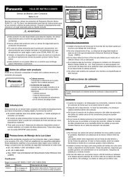
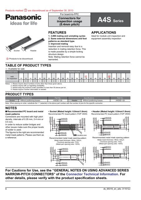
FEATURES<br />
1. 3,000 mating and unmating cycles<br />
2. Same external dimensions and foot<br />
patterns as standard type.<br />
3. Improved mating<br />
Insertion and removal easy due to a<br />
reduction in mating retention force. This<br />
is made possible by a simple locking<br />
structure design.<br />
Note: Mating retention force cannot be<br />
warranted.<br />
APPLICATIONS<br />
Ideal for module unit inspection and<br />
equipment assembly inspection<br />
TABLE OF PRODUCT TYPES<br />
✩: Available for sale<br />
Product name<br />
Number of pins<br />
A4S<br />
for inspection 10 12 14 16 18 20 22 24 26 28 30 32 34 36 38 40 44 50 54 56 60 64 70 80<br />
✩ ✩ ✩ ✩ ✩ ✩ ✩ ✩ ✩ ✩ ✩ ✩ ✩ ✩ ✩ ✩ ✩ ✩ ✩ ✩ ✩ ✩ ✩ ✩<br />
Notes: 1. Please inquire about numbers of pins other than those given above.<br />
2. Please inquire with us regarding availability.<br />
3. Please keep the minimum order quantities no less than 50 pieces per lot.<br />
4. Please inquire if further information is needed.<br />
PRODUCT TYPES<br />
Specifications Part No. Specifications Part No.<br />
Socket Without positioning bosses AXE5E26 Header Without positioning bosses AXE6E26<br />
Note: When placing an order, substitute the “” (asterisk) in the above part number with the number of pins for the specific connector.<br />
NOTES<br />
■ Recommended PC board and metal<br />
mask patterns<br />
Connectors are mounted with high pitch<br />
density, intervals of 0.35 mm, 0.4 mm or<br />
0.5 mm.<br />
In order to reduce solder bridges and<br />
other issues make sure the proper levels<br />
of solder is used.<br />
The figures to the right are recommended<br />
metal mask patterns. Please use them as<br />
a reference.<br />
• Socket (Mated height: 0.8mm/1.0mm)<br />
Recommended PC board pattern (TOP VIEW)<br />
2.90±0.03<br />
1.06±0.03<br />
(0.92)<br />
0.40±0.03<br />
0.23±0.03<br />
0.90±0.03<br />
1.45±0.03<br />
(0.50)<br />
0.20±0.03<br />
1.90±0.03<br />
C 0.30<br />
: Insulation area<br />
Recommended metal mask opening pattern<br />
Metal mask thickness: When 120m<br />
(Terminal opening ratio: 70%)<br />
(Metal-part opening ratio: 100%)<br />
2.90±0.01<br />
1.06±0.01<br />
(0.92)<br />
0.40±0.01<br />
0.20±0.01<br />
(0.40)<br />
2.00±0.01<br />
2.80±0.01<br />
• Header (Mated height: 0.8mm/1.0mm)<br />
Recommended PC board pattern (TOP VIEW)<br />
1.66±0.03<br />
0.60±0.03<br />
(0.53)<br />
0.40±0.03<br />
0.23±0.03<br />
0.45±0.03<br />
0.80±0.03<br />
Recommended metal mask opening pattern<br />
Metal mask thickness: When 120m<br />
(Terminal opening ratio: 70%)<br />
(Metal-part opening ratio: 100%)<br />
1.66±0.01<br />
0.60±0.01<br />
(0.53)<br />
0.40±0.01<br />
0.20±0.01<br />
(0.65)<br />
1.10±0.03<br />
2.40±0.03<br />
(0.52)<br />
1.26±0.01<br />
2.30±0.01<br />
0.90±0.01<br />
1.45±0.01<br />
C 0.30<br />
0.45±0.01<br />
0.80±0.01<br />
For Cautions for Use, see the “GENERAL NOTES ON USING ADVANCED SERIES<br />
NARROW-PITCH CONNECTORS” of the Connector Technical Information. For<br />
other details, please verify with the product specification <strong>sheet</strong>s.<br />
6 ds_65316_en_a4s: 311012J