Crathco® Visual Granita Machine - YouNeedADrink.com
Crathco® Visual Granita Machine - YouNeedADrink.com
Crathco® Visual Granita Machine - YouNeedADrink.com

Create successful ePaper yourself
Turn your PDF publications into a flip-book with our unique Google optimized e-Paper software.
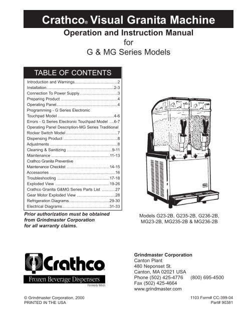
Crathco® <strong>Visual</strong> <strong>Granita</strong> <strong>Machine</strong><br />
Operation and Instruction Manual<br />
for<br />
G & MG Series Models<br />
TABLE OF CONTENTS<br />
Introduction and Warnings......................................2<br />
Installation............................................................2-3<br />
Connection To Power Supply..................................3<br />
Preparing Product ..................................................4<br />
Operating Panel......................................................4<br />
Programming - G Series Electronic<br />
Touchpad Model ..................................................4-6<br />
Errors - G Series Electronic Touchpad Model ....6-7<br />
Operating Panel Description-MG Series Traditional<br />
Rocker Switch Model ..............................................7<br />
Dispensing Product ................................................8<br />
Adjustments ............................................................8<br />
Cleaning & Sanitizing ........................................9-11<br />
Maintenance ....................................................11-13<br />
Crathco <strong>Granita</strong> Preventive<br />
Maintenance Checklist ......................................14-15<br />
Accessories ..........................................................16<br />
Troubleshooting ..............................................17-18<br />
Exploded View ................................................19-26<br />
Crathco <strong>Granita</strong> G&MG Series Parts List ............27<br />
Gear Motor Exploded View ..................................28<br />
Refrigeration Diagrams....................................29-30<br />
Electrical Diagrams..........................................31-33<br />
Prior authorization must be obtained<br />
from Grindmaster Corporation<br />
for all warranty claims.<br />
Models G23-2B, G235-2B, G236-2B,<br />
MG23-2B, MG235-2B & MG236-2B<br />
Grindmaster Corporation<br />
Canton Plant<br />
480 Neponset St.<br />
Canton, MA 02021 USA<br />
Phone (502) 425-4776 (800) 695-4500<br />
Fax (502) 425-4664<br />
www.grindmaster.<strong>com</strong><br />
© Grindmaster Corporation, 2000<br />
PRINTED IN THE USA<br />
1103 Form# CC-399-04<br />
Part# 90381
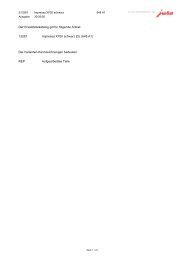
Introduction and Warnings<br />
This instruction manual is an important part of this <strong>Granita</strong> machine and must be kept for future reference.<br />
Carefully read the warnings contained in this instruction manual before installing and operating this <strong>Granita</strong><br />
machine.<br />
Instructions For <strong>Machine</strong> Transport<br />
NOTE: Refrigeration equipment must remain upright to avoid damage to the <strong>com</strong>pressor<br />
In order to prevent the oil contained in the <strong>com</strong>pressor from flowing into the cooling<br />
circuit, it is necessary to always ship, carry, store and handle this <strong>Granita</strong> machine in<br />
an upright position, following the instructions located on the packaging. Never ship,<br />
carry, store or handle unit on its side.<br />
Installation<br />
1.) Cut banding straps from box and lift the box off the machine (see fig. A).<br />
2.) Positioning the machine<br />
• The machine must be well ventilated. Leave an 8” (20 cm) clearance on the<br />
sides and back of the machine to allow proper ventilation. Installation of the<br />
machine near a heat source should be avoided. Some heat sources you should<br />
avoid locating this unit too close to are ovens, coffee machines, cold or frozen<br />
beverage dispensers or ice machines (equipment with <strong>com</strong>pressors that expel<br />
hot air through its vents). <strong>Machine</strong>s should also not be positioned near dust producing<br />
units such as a Powdered Cappuccino or Cocoa dispenser. A room temperature<br />
between 59°F (15°C) and 77°F (25°C) is re<strong>com</strong>mended (see fig. B).<br />
(Figure A)<br />
• The lit merchandising covers are reversible (front to back) depending upon the<br />
needs of the operator (see fig. B).<br />
3.) Remove Shipping Pin<br />
!<br />
Attention: Shipping pin attached to tag located behind<br />
each bowl must be removed before starting machines.<br />
(Figure B)<br />
8"<br />
(20 cm)<br />
• Lift up and remove rear back-lit merchandiser panel (see fig. C). NOTE: Some units may have dual rear<br />
back-lit merchandiser panels, these function in the same manner as the single panel rear merchandisers.<br />
• Pull out each pin attached to each tag (see fig. D)<br />
• Replace rear back-lit merchandiser panel (see fig. E).<br />
Page 2<br />
(Figure C) (Figure D) (Figure E)<br />
G & MG Series <strong>Granita</strong> <strong>Machine</strong>
Installation (cont.)<br />
4.) Installing the Top Lid Merchandiser (requires Phillips head screwdriver)<br />
• Unplug the cord to the lid and remove the lid from the machine.<br />
• On top of the cover, remove the 4 hole plugs over the front (2) screws,<br />
middle (near rocker switch) and back screws then remove these 4 screws<br />
with a Phillips head screwdriver. Remove the black top part of the cover<br />
from the clear plastic base. (see fig. E)<br />
• Slide the merchandiser header around the outside edge of the lid’s clear<br />
plastic base. Position bottom edge of header in grooved area. (see fig. F)<br />
• Reassemble the black top cover onto the clear plastic base. The top edge of<br />
header should slide into black top cover grooved area. (see fig. F) Replace<br />
screws. Replace hole plugs (the angled plugs goes in the rear hole, and the<br />
two large plugs go in the two front holes and the small plug goes in the<br />
center hole by the rocker switches).<br />
• Replace assembled lid on machine and reattach cord.<br />
5. Installing the Rear Back-lit Merchandiser<br />
• To remove any existing artwork, bend or pinch the middle of the back-lit<br />
merchandiser and pull it from the rear merchandising display casing.<br />
(see fig. G)<br />
• To insert new art, slide the left corner edges into the left top and bottom<br />
casing edges. (see fig. H)<br />
• Slightly bend art and insert the right side of art into the right top and bottom<br />
casing edges. (see fig. H)<br />
• Smooth out art until all edges are properly inserted into the casing.<br />
Connection To Main Power Supply<br />
(Figure E)<br />
(Figure F)<br />
(Figure G)<br />
(Figure H)<br />
!<br />
Attention: Before inserting the plug into the electrical<br />
outlet, carefully read the following precautions.<br />
• The electrical safety of this <strong>Granita</strong> machine can only be achieved if the machine is properly connected<br />
to an appropriate grounded, electrical receptacle that is in <strong>com</strong>pliance with current national safety standards.<br />
Therefore, the manufacturer cannot be held responsible for damage and/or injury caused by failure<br />
to connect the unit to an appropriate source of power.<br />
• For a safe and correct installation, connect the unit to a dedicated outlet.<br />
• Do not alter the cord or plug in any way.<br />
!<br />
Attention: Altering the cord or plug will void the warranty.<br />
• The entire length of the power supply cord must not, in any way, be <strong>com</strong>pressed (bent or bunched<br />
together) nor may extension cords be used.<br />
• Do not obstruct the ventilation and heat dispersion grill vents on the side and rear panels of the unit. An<br />
insufficient ventilation process may reduce the efficiency of the machine, causing it to function inadequately,<br />
and cause serious damage to the machine. A minimum of eight inches (20cm) clearance is<br />
necessary on each side and behind the unit.<br />
G & MG Series <strong>Granita</strong> <strong>Machine</strong> Page 3
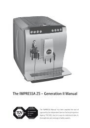
Preparing Product<br />
! Attention: Make sure that the mixture has a 13% minimum<br />
Brix (sugar content). A lower concentrate could seriously damage<br />
the mixing parts, as well as the gear motors. NEVER USE ONLY<br />
WATER.<br />
1.) If using product concentrate (instead of ready-to-use product), dilute and mix the product<br />
with water, according to the directions given by the manufacturer, in a separate<br />
container (see fig. I). Never pour dry powder, crystals, or concentrate into a dry<br />
bowl.<br />
2.) Slide the merchandising lid either forward or toward the back of the bowl until the<br />
“stops” reach the edge of the bowl. (It is not necessary to remove the merchandising<br />
cover.) When sliding lid back make sure that no droplets of water <strong>com</strong>e off lid.<br />
Pour the prepared product into the bowl (see fig. J). Do not spill any material on lid<br />
or on bowl. There is a minimum and maximum fill line on the bowl. Do not overfill<br />
or run the unit without enough product. Running unit with product below the minimum<br />
full line may cause damage to the unit.<br />
3.) Insert the plug into a dedicated electrical outlet.<br />
(Figure I)<br />
(Figure J)<br />
Operating Panel<br />
In order to access the operating panel, lower the cover (A) as shown<br />
(Figure K)<br />
in figure K. To lower the cover use a coin or other object to turn the keyless lock to the horizontal position.<br />
Operating Panel -Electronic Touchpad<br />
LED<br />
Auger ON/OFF<br />
Press To Select<br />
Function<br />
COLD<br />
FROZEN<br />
OFF<br />
COLD<br />
FROZEN<br />
OFF<br />
AUGER ON/OFF<br />
PRESS TO SELECT<br />
FUNCTION<br />
ON<br />
OFF<br />
AUTO TIMER<br />
AUTO TIMER<br />
(Figure L)<br />
Programming G Series Electronic Touchpad Models<br />
Models G23-2B, G235-2B & G236-2B Electronic Touchpad:<br />
Main Power Switch:<br />
1.) Turns unit ON.<br />
2.) Selects 12/24 time or FÞ/CÞ temperature display when turned ON while simultaneously depressing the auger<br />
button.<br />
3.) Sets current time when turned ON while simultaneously depressing the “Mode/Press To Select Function”<br />
button.<br />
Page 4<br />
G & MG Series <strong>Granita</strong> <strong>Machine</strong>
Model G23-2B Electronic Touchpad (cont.):<br />
Auger ON/OFF Button:<br />
1.) Turns auger ON and OFF when main power switch is ON.<br />
2.) Must be ON to permit defrost time to be reset.<br />
3.) Must be ON to activate the “Mode/Press To Select Function” button to select manual “OFF”, “FREEZE” or<br />
“COOLING” functions.<br />
Mode/Press To Select Function Button:<br />
1.) Used to manually select “OFF”, FREEZE” or “COOLING” functions when auger is turned ON.<br />
2.) Accesses defrost timer reset mode when depressed for an extended period when auger is turned ON.<br />
3.) Locks in hours, minutes and final time settings after they are reset using the “Auto Timer” button.<br />
4.) Does not function when light on “Auto Timer” button is illuminated.<br />
“Auto Timer” button<br />
1.) Turns auto defrost mode ON or OFF (light on switch indicates when auto defrost mode is activated).<br />
2.) Used to adjust the hours and minutes settings when readjusting current time or auto defrost timer.<br />
Enter Time Programming on Initial Installation or in the Event of a Time Change:<br />
1.) Turn OFF power switch.<br />
2.) While pressing left “Press To Select Function” button, turn ON power switch while continuing to hold the “Press<br />
To Select Function” button until the display illuminates (hour digits will start to blink).<br />
3.) First set hour by pressing the “Auto Timer” clock button until the appropriate hour is shown (note: when using a<br />
12 hour clock the time is P.M. when the dot at the bottom right corner of the LED is lit; when dot is not lit it is<br />
A.M.)<br />
4.) To set the minutes press the left “Press To Select Function” button, then press the “Auto Timer” clock button<br />
until the appropriate minutes are set.<br />
5.) To save your settings press the “Press To Select Function” button one more time.<br />
Setting Defrost Timer (Night Setting):<br />
1.) Turn power switch ON.<br />
2.) Then press “Auger ON/OFF” button on for the side you are setting.<br />
3.) Then press and hold the “Press To Select Function” button until you hear a long beep and the LED, “cold” and<br />
the “Auto Timer” clock light begins to blink.<br />
4.) Press the “Auto Timer” clock button to set the hour you want it to turn to refrigeration mode and then press the<br />
“Press To Select Function” button to save the setting.<br />
G & MG Series <strong>Granita</strong> <strong>Machine</strong> Page 5
Setting Defrost Timer (Night Setting) (cont.):<br />
5.) Then press the “Auto Timer” clock button to set the minutes to <strong>com</strong>plete time setting that you want it to turn to<br />
refrigeration mode, (defrost mode). Then press the “Press To Select Function” button to save the setting.<br />
6.) Proceed to setting the time you want the machine to turn to freezing mode by following steps 4 and above.<br />
Then press the “Press To Select Function” button to save the time settings for freeze mode. Freeze light<br />
should be blinking.<br />
Note: Once the settings have been saved, the unit will save the settings, even when the power switch is turned OFF.<br />
When the light on the “Auto Timer” clock button is “on”, the defrost timer is activated. To turn OFF the defrost timer,<br />
press the “Auto Timer” clock button(s) until the light(s) on the clock button(s) turns off.<br />
Operate in Automatic Mode (with Defrost Timer Activated):<br />
1.) Turn power switch ON and wait for LED to light up.<br />
2.) Press auger button “ON” for the side you are setting.<br />
3.) To operate in defrost mode press the “Auto Timer” button until it is illuminated.<br />
4.) When setting automatic times, please keep in mind it will take time for the frozen product to be<strong>com</strong>e liquid or<br />
vice versa.<br />
Operate in Manual Mode (without Defrost Timer Activated):<br />
1.) Turn power switch ON and wait for LED to light up.<br />
2.) Make sure clock button is OFF (LED light on clock button should not be lit up).<br />
3.) First turn auger on by pressing “Auger ON/OFF” button until it beeps. (Note: The auger must be on before unit<br />
will allow the cooling or freezing mode to activate)<br />
4.) Then select refrigeration or freezing mode by pressing the “Press To Select Function” button until the light<br />
under the selection you desire is lit up. (Note: In the cooling mode, the LED will read the actual temperature of<br />
the product {The temperature setting is preset to NSF standards and is not adjustable.}) In the freezing mode<br />
the LED will read the current time.<br />
G SERIES MODELS - ERROR MESSAGES<br />
1.) “FILTER CLEANING” ALARM<br />
A filter cleaning alarm will activate when the unit is running hot due to insufficient internal air circulation.<br />
When this occurs a “Filtr” message will appear on the touchpad LED readout and an intermittent audible tone<br />
will also sound to alert the operator of this condition.<br />
The “Filtr” message will appear when the alarm activates (a beeping sound every 4-5 seconds). To determine<br />
the condition that caused the alarm and correct problem, see list of conditions below:<br />
• Condition: The filter is dirty and needs to be cleaned. - Corrective Action: Clean and replace filter following<br />
instructions on page 11 (Removing and Cleaning Filter).<br />
• Condition: The unit is positioned too close to a wall or other object restricting air flow and causing the<br />
machine to run at a higher temperature. - Corrective Action: Reposition unit to maximize ventilation space<br />
(see page 2 - installation figures).<br />
• Condition: The filter is not properly installed. - Corrective Action: Properly install filter see “Removing and<br />
cleaning filter” page 11.<br />
• Condition: The unit has been installed near a heat source, such as a coffee machine, ice maker or cold<br />
beverage machine which expels hot air from its vents, causing the machine to run at a high temperature.<br />
(Installation near a heat source should be avoided) - Corrective Action: Reposition unit to maximize ventilation<br />
space (see page 2 - installation figures).<br />
Page 6<br />
G & MG Series <strong>Granita</strong> <strong>Machine</strong>
G SERIES MODELS - ERROR MESSAGES (CONT.)<br />
2.) “SYSTEM OVER TEMPERATURE” ALARM<br />
• A system over temperature alarm will activate as a safety when the unit has overheated to protect the<br />
<strong>com</strong>pressor.<br />
• The system automatically goes to “OFF” status where the <strong>com</strong>pressor’s operations is stopped, while<br />
augers will keep working to avoid forming ice blocks.<br />
• When this occurs an “Err” message will appear on the touch pad LED readout ac<strong>com</strong>panied by a continuous<br />
buzzer sound to alert the operator of this condition.<br />
• When this alarm activates, turn off all switches. Then determine the condition. (See “Filter Cleaning” Alarm<br />
Section for Conditions and Corrective Actions)<br />
Operating Panel Description-MG Series Traditional<br />
Rocker Switch Model<br />
1.) Turn ON the main power switch (D) (see figure M)<br />
2.) Description of the buttons (see figure cc):<br />
Each bowl is controlled by three switches which have the following functions:<br />
(E) activates the mixing parts/spiral auger<br />
(F) activates the freezing of the product<br />
(G) activates the refrigeration of the product (night/defrost setting)<br />
To obtain a slush:<br />
Select the (E) switch to activate the mixing parts/spiral auger and<br />
select the (F) switch to activate the freeze mode.<br />
Note: There is a 4 minute delay before the <strong>com</strong>pressor will start.<br />
(Figure M)<br />
To obtain cold (night/defrost) drinks:<br />
Select the (E) switch to activate the mixing parts/spiral auger and<br />
select the (G) switch to activate the refrigeration mode.<br />
Stand-by mode setting:<br />
Select the (E) switch to activate the mixing parts/spiral auger and the (G) switch to activate refrigeration<br />
mode to keep the product(s) in bowl(s) overnight.<br />
Defrost Timer Operating Instructions<br />
1.) SETTING CURRENT TIME - Rotate the program disc, in the direction of<br />
the arrows, to align the correct time of day with the time of day mark.<br />
Figure H shows the timesetting of 7:00.<br />
2.) SETTING DEFROST MODE - Set the defrost period by pushing the switch<br />
actuator toward the outer edge of the program disc. Freeze time is set by pushing the (Figure N)<br />
switch actuators toward the center of the time switch. Figure N shows a defrost time<br />
from 11:00 to 6:15. The light and dark shaded areas of the program disc indicate day and night respectively.<br />
Each actuator is equivalent to 15 minutes.<br />
3) All switches (power, auger, refrigeration and freeze) must be “on” for defrost timer to properly function.<br />
NOTE: The timer is battery backed. Do not remove power from the unit for greater than 2 weeks as doing so will<br />
result in failure of the battery back-up feature. The battery is nickel cadmium and will last from 6 to 8 years if<br />
properly charged. The battery is not replaceable upon failure.<br />
G & MG Series <strong>Granita</strong> <strong>Machine</strong> Page 7
Dispensing Product<br />
To dispense the product, position the cup under the dispensing valve (C)<br />
and lower the dispensing lever (B) (see fig. O).<br />
! Attention: If the machine is turned off at night, with the bowls filled,<br />
or just partially filled, a layer of solid ice may form on the surface due to the<br />
natural separation of the unmixed (non-moving) product. In this case, before<br />
turning the machine back on, remove the layer of superficial ice to prevent<br />
damage to the mixing auger.<br />
Adjustments<br />
(Figure O)<br />
!<br />
Attention: To prevent the product from be<strong>com</strong>ing too thick,<br />
it is necessary to push left “Press To Select Function” and right<br />
“Press To Select Function” keys to cold drink position or to refill<br />
the bowl when the level of the granita inside the bowl is below the<br />
minimum fill line.<br />
Consistency Adjustment<br />
1.) Unplug the machine.<br />
2.) Be sure that product in bowl is within proper fill range.(Above the minimum<br />
fill line)<br />
3.) Remove merchandiser.<br />
4.) Change the thickness of the product by turning the screw (D) on the back of<br />
the bowl, as shown on fig. P. Turn the screw clockwise for thinner product or<br />
counterclockwise for thicker product. The indicator gauge (D1), located on<br />
the back of the bowl, shows the degree of adjustment (+/-). (+) = thicker,<br />
(-) = thinner<br />
Note: This (D1) is an indicator gauge only. To adjust consistency, turn screw<br />
on top (D).<br />
(Figure P)<br />
(Figure Q)<br />
Page 8<br />
G & MG Series <strong>Granita</strong> <strong>Machine</strong>
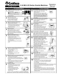
Cleaning and Sanitizing Procedures<br />
! Warning Disconnect the unit from its power supply<br />
prior to cleaning or sanitizing the unit. Failure to do so may<br />
result in electric shock.<br />
Daily Cleaning<br />
For the machine to function properly, it is important that<br />
the cleaning procedures be carried out daily, according<br />
to the following instructions:<br />
(Figure R)<br />
1.) Turn off the / (G, fig. M) refrigeration and / (F, fig. M) freezing<br />
switches and empty the bowl of its remaining product; after draining the product<br />
from the unit, you can fill the bowl with hot water (not boiling) to help melt<br />
off any sugar deposits. Then drain the water prior to proceeding to step (2).<br />
(Figure S)<br />
2.) Unplug the unit.<br />
3) Pull out the mixing rod (E) by pushing it slightly backwards<br />
to remove it from its position (see fig. Q on pg.8).<br />
4.) Unscrew and remove the two knobs (F) then lower the bowl to<br />
drain out any remaining product through the dispensing valve<br />
(see fig. R).<br />
(Figure T)<br />
5.) Remove and disassemble the dispensing valve:<br />
• Remove the pin (G) as shown (see fig. S).<br />
Then, remove the handle (B) sliding it from its seat.<br />
• Simultaneously apply pressure to the two securing tabs (H) and<br />
lift the dispensing valve (C) to pull it out of its position (see fig. T).<br />
6.) Remove the bowl (L) by unscrewing the two knobs (F) and<br />
pulling it downwards as shown in fig. U.<br />
(Figure U)<br />
7.) Unscrew the securing bolt (M) clockwise. Pull off the auger (N)<br />
and remove the shaft seal (O) and the bowl seal (P) (see fig. V).<br />
8.) Remove the drain tray by lifting up on the front edge, while lowering the<br />
rear edge, and then lift it off the unit (see fig. W).<br />
(Figure V)<br />
9.) Thoroughly wash each part that has been removed in steps 1-8 and the base<br />
(Q), as well as the freezing cylinder (R) with warm water and mild dishwashing<br />
detergent. Rinse well with clear water and allow to air dry (see<br />
fig. X). Avoid the use of abrasive cleaners which can damage the finish.<br />
Do not put in dishwasher. Dishwasher may damage some parts such as<br />
the clear plastic auger gears and top mixing bar. Reassemble with clean<br />
hands.<br />
(Figure W)<br />
(Figure X)<br />
G & MG Series <strong>Granita</strong> <strong>Machine</strong> Page 9
Cleaning and Sanitizing Procedures (con’t)<br />
10.) Reassemble the mixing unit back together, according to the following<br />
procedures (see fig. Y):<br />
• Moisten the bowl seal (P) with water and slip it into place at the back of cylinder<br />
with ribs angled toward back of freezer.<br />
• Apply food grade lubricant to the inside of the shaft seal (O) and put the shaft<br />
seal (O) back on with the flared end of seal toward back of freezer.<br />
(Figure Y)<br />
• Put the auger assembly (N) back on the evaporator.<br />
• Secure all the parts in place by screwing on the bolt (M) counterclockwise.<br />
11.) Reassemble the bowl (L), positioning it into place. Make sure that the bowl fits<br />
tightly to the bowl seal (see fig. Z). We also suggest that the rear part of the<br />
bowl be moistened with water or lightly lubricated at the point where it fits<br />
together with the seal to make it easier to install bowl.<br />
11a.) The lower right and left bowl flanges should fit on the outside of each black triangle<br />
edge (see fig. AA). The lid cover will not fit properly if this is not correctly<br />
positioned.<br />
12.) Secure the bowl (L) by keeping it lifted until the bolt (M) is aligned with its hole<br />
(S), then tightly screw on the knobs (F) without exerting excessive pressure to<br />
avoid cracking the bowl (see fig. BB).<br />
13.) Reassemble the mixing rod (O) so that its gears are aligned with the lower gear<br />
ring. This will allow the front pin to fit perfectly in its position on the bowl (see fig.<br />
CC).<br />
14.) Reassemble in sequence the parts of the dispensing valve<br />
as follows (see fig. DD).<br />
• Make sure that the dispensing valve seat is properly<br />
lubricated with food-grade lubricant (such as Haynes Lubrifilm).<br />
• Put the dispensing valve body (T) in its seat.<br />
• Insert the spring (U).<br />
• Put the dispensing valve upper body (V) into its position<br />
until it <strong>com</strong>pletely snaps into place.<br />
• Reassemble the handle (B) and insert retaining pin (G)<br />
following the same procedures in #5, fig. S.<br />
15.) Reinstall the drain tray (fig. T). Make sure that the condensation<br />
drainage tube (J) is reinserted into its correct fixed position, allowing it to<br />
drain into the tray.<br />
(Figure Z)<br />
(Figure AA)<br />
(Figure BB)<br />
(Figure CC)<br />
Bowl outside<br />
corner must be<br />
over the white<br />
plastic edge.<br />
(Figure DD)<br />
Page 10<br />
G & MG Series <strong>Granita</strong> <strong>Machine</strong>
Cleaning and Sanitizing Procedures (con’t)<br />
16.) Plug the unit back into appropriate power supply.<br />
17.) After the cleaning and reassembly of the mixing parts and bowl as per above instructions, fill the bowl with a<br />
mix of water and an approved cleaning solution (example kay5), according to the measures specified.<br />
18.) Start the mixing part of the machine for about 10 minutes to sanitize all parts. Follow the cleaning solution<br />
specifications.<br />
19.) Drain the cleaning solution as follows:<br />
• Unscrew the two knobs (F) see fig. U);<br />
• then lower the bowl to drain out any remaining product through the dispensing valve (C)<br />
(as shown in fig. U).<br />
20.) Screw again the knobs (F) to fix the bowls.<br />
21.) With a clean cloth wash the underside of the lamp cover with warm water and a mild detergent. Allow this<br />
part to air dry and then wipe it with a clean cloth which has been dipped in the sanitizing mixture.<br />
Prepare a minimum of 4 gallons (15 liters) of sanitizing solution (Stera Green<br />
Label or equivalent) following the manufacturer’s instructions.<br />
Note: Add 4 ounces of Stera Sheen to 4 gallons (15 liters) of 120° Fahrenheit<br />
(50° Centigrade) water to achieve a concentrate of 100 parts per million.<br />
!<br />
Warning: Lamp cover must be unplugged. Electric shock<br />
could occur if cover or power cord <strong>com</strong>e in contact with<br />
solution.<br />
(Figure EE)<br />
Maintenance<br />
! Warning: Disconnect the unit from its power supply prior to<br />
performing any maintenance procedures. Failure to do so could result in<br />
electric shock, injury from hazardous moving parts or serious burns from<br />
hot surfaces.<br />
Removing and cleaning the filter (Weekly)<br />
This should be done weekly or more often if necessary.<br />
In order to guarantee an efficient refrigerating system, it is essential that the<br />
filter be properly cleaned, according to the following procedures:<br />
1) Unplug the machine.<br />
(Figure FF)<br />
2) Unscrew the knob (K) in order to remove back panel (see fig. FF).<br />
3) Remove the filter (W) held inside the back panel (X) and clean<br />
it properly using water or vacuum (see fig. GG).<br />
4) Place the cleaned filter back inside back panel and reinstall the back<br />
panel on the machine by screwing in the knob (K).<br />
(Figure GG)<br />
!<br />
Attention: Failure to maintain a clean filter and condenser will<br />
cause damage to the unit not covered by warranty.<br />
G & MG Series <strong>Granita</strong> <strong>Machine</strong> Page 11
Maintenance (con’t)<br />
Cleaning the Condenser (Monthly)<br />
This cleaning should be done monthly or more often if necessary.<br />
In order to guarantee an efficient refrigerating system, it is essential that the<br />
condenser be properly cleaned at regular intervals, according to the following<br />
procedures:<br />
• Unplug the machine.<br />
(Figure HH)<br />
• Remove the back panel and filter. Using a dry brush or vacuum, remove the dust that<br />
has accumulated between the fins of the condenser (see fig HH).<br />
Replacing the Lightbulbs (As Needed)<br />
• Unplug the machine.<br />
Lid Lights<br />
• Unplug the cord to the lid and remove the lid from the machine.<br />
• In order to access the lightbulb in the merchandising cover, insert<br />
a quarter in the slot on the small panel on the top of the cover (DA)<br />
and rotate the quarter to pop the panel open (see fig. II).<br />
(Figure II)<br />
• Holding the merchandising cover with the top open, carefully remove the<br />
lightbulb (see fig. JJ).<br />
• Insert the new bulb and replace the light cover.<br />
• Place lid on machine and plug lid cord back into lid.<br />
(Figure JJ)<br />
Rear Merchandiser Lights<br />
• In order to access the lightbulb from the rear back-lit merchandiser (BB),<br />
remove the rear merchandiser by sliding it upwards (see fig. KK).<br />
NOTE: Some units may have dual rear backlit merchandiser panels, these<br />
function in the same manner as the single panel rear merchandisers.<br />
• Then remove the lightbulb(s) (BA) (see fig. LL).<br />
• Insert the new bulb(s) (BA).<br />
• Reassemble the rear back-lit merchandiser (AA) making sure that its slots<br />
are inserted properly in the relevant brackets (CA) (see fig. LL).<br />
(Figure KK)<br />
• Plug machine into dedicated outlet.<br />
Page 12<br />
(Figure LL)<br />
G & MG Series <strong>Granita</strong> <strong>Machine</strong>
Maintenance (con’t)<br />
Seal Maintenance<br />
Bell Shaped Seal<br />
• Replace every 1 to 6 months depending on conditions of use and level of maintenance and lubrication.<br />
This part should be lubricated during re-assembly after every cleaning.<br />
Spindle Bushing Seal<br />
• Replace every 6 to 12 months depending on conditions of use and level of maintenance.<br />
Replacement of spindle bushing should ONLY be done by a qualified service technician.<br />
To Replace Spindle Bushing:<br />
Tools required: Power screwdriver, Rubber mallet, Replacement Kit #90104, spindle bushing extraction tool<br />
#90544<br />
Each PM kit # 90104 contains 2 bell shaped shaft seals, 2 spindle bushing seals, 4 dispense valve o-rings, 1 laminated<br />
care and cleaning card and one PM checklist.<br />
1. Empty product bowl and disassemble as if for cleaning. Spindle bushing seals should be replaced every<br />
6-12 months and bell-shaped shaft seals should be replaced once every 1-6<br />
months depending on conditions of use and maintenance.<br />
2. Slide the threaded metal cylinder on the drive shaft so that the flat surface meets<br />
the face of the evaporator cylinder.<br />
3. Thread the two tapping screws (max length 1 1/8”) through the holes in the tool<br />
and into the spindle bushing seal. Use of a power screwdriver is suggested. (See<br />
Figure MM)<br />
4. Screw the outer cylinder of the extracting tool on to the metal cylinder by rotating<br />
clockwise until it is fully connected.<br />
Figure MM<br />
5. Continue turning the outer cylinder clockwise until the spindle bushing seal is removed.<br />
If necessary, apply higher torque by inserting a screwdriver in the holes of the outer<br />
cylinder. (See Figure NN)<br />
6. After extracting the old spindle bushing seal, position a new one in the evaporator<br />
cylinder. The gasket (black side) should be facing the inside of the evaporator.<br />
7. Position the inserting pipe so that it’s smaller diameter touches the spindle bushing<br />
seal.<br />
Figure NN<br />
8. Push the spindle bushing seal in by tapping on the pipe with a rubber mallet. Be<br />
sure the spindle bushing seal is <strong>com</strong>pletely in place. (See Figure OO)<br />
9. Reassemble bowl.<br />
Figure OO<br />
When replacing the spindle bushing be sure to check the condition of the driveshaft. If the<br />
surface is not smooth and the driveshaft is not secure, then replace the driveshaft while replacing the spindle bushing.<br />
Replacement of a driveshaft should only be done by a qualified service technician using PM kit #90110.<br />
Bowl Gasket (located at rear of bowl)<br />
• Replace as necessary depending on the conditions of use and level of maintenance. This part should be<br />
lubricated during re-assembly after every cleaning.<br />
O-Ring Maintenance<br />
•O-rings should be replaced every 6 to 12 months or as necessary where wear is apparent.<br />
G & MG Series <strong>Granita</strong> <strong>Machine</strong> Page 13
Crathco <strong>Granita</strong> Preventive<br />
Maintenance (PM)<br />
Checklist for Kit 90566 -<br />
Serial # 11259 and above<br />
(and units with lower serial #’s that have been<br />
converted to stainless steel shafts - units with<br />
black stainless shafts will need to be converted<br />
using PM Kit # 90110B)<br />
A preventive maintenance visit should be performed every 6 months. In addition, air filter should be cleaned weekly,<br />
and every three months the condenser should be cleaned, and the rubber shaped bell shaft seals should be<br />
replaced. Failure to <strong>com</strong>plete PM’s every 6 months is considered abuse of the machine, and therefore voids the<br />
warranty. Proof of PM must be documented with Grindmaster Corporation to maintain warranty coverage. To document<br />
your PM, <strong>com</strong>plete this form with signatures, place used/worn parts that were replaced during the PM inside<br />
envelope, and mail to Grindmaster Corporation. Parts returned should include 2 evaporator seals, 2 rubber bell<br />
shaped shaft seals, valve o-rings and shafts (if applicable). First PM on serial numbers 11259 to 12202 should also<br />
include kit number 90225 (one per serial number).<br />
The following procedures should be performed during a Preventative Maintenance visit, using PM kit # 90566<br />
or 90110B.<br />
Document model and serial number of equipment and record above.<br />
Check product temperature and consistency for proper setting - adjust if necessary.<br />
Insure product is being mixed properly and is within specification (check and document brix - most products<br />
should be around 13% - refer to product manufacturer’s re<strong>com</strong>mendations for exact re<strong>com</strong>mended brix).<br />
Record Brix reading here: Left Bowl _____ Right Bowl _____<br />
Check for leaks at gaskets, o-rings, front shaft seal, etc.<br />
Empty product from bowls and disassemble unit <strong>com</strong>pletely.<br />
Clean and sanitize all disassembled parts.<br />
Clean and sanitize top tray and freezing barrel.<br />
Clean out condensation tube with sanitizer and long brush.<br />
Check condition of all panels, bowls, lids - replace if necessary.<br />
Check mixing rods and augers for wear, check mixing rod bearing for wear - replace if necessary.<br />
Check for bowl knobs (two per bowl to lock down bowl in front) - replace if necessary.<br />
Check operation of lights in lid and rear of unit (if equipped) - replace light bulbs if necessary.<br />
Clean re-usable air filter. Check condition of filter and replace if necessary.<br />
Clean condenser.<br />
Check condition of bowl gaskets and replace if necessary.<br />
Replace all o-rings on dispense valves and lubricate.<br />
Check drive shaft. Replace if necessary, using PM kit #90110B in place of 90566 above.<br />
Replace evaporator seal in front of evaporator. (use brass tool, included, to slide seal onto shaft, and use the<br />
white tool to tap seal into place. Be sure to lubricate seal with food grade grease first)<br />
Replace bell shaped rubber shaft seal on front of freezing barrel (generously lubricate inside seal)<br />
Lubricate parts where appropriate (dispense valve o-rings, inside of shaft seal, inner rim of bowl where it meets<br />
with the bowl seal)<br />
Re-assemble unit and refill with product<br />
Verify and document defrost timer setting and operation and time of day setting and adjust if necessary.<br />
Check thermostat setting on MG models. Thermostat setting should be between 1-1/2 and 2.<br />
Verify <strong>com</strong>pressor operation and freezer controller operation.<br />
Verify ventilation is adequate (8” on both sides and back)<br />
Check electrical connections and wiring.<br />
Check fan operation (1 condenser fan and 2 gear motor fans) and clean fan or blades if necessary.<br />
Review proper periodic care and cleaning instructions (disassembly, cleaning, sanitizing, lubrication and<br />
re-assembly) with store personnel. Review proper product mixing and handling instructions with store personnel<br />
Demonstrate and train store personnel to follow proper procedures (stress importance of store level<br />
maintenance such as lubrication and filter cleaning).<br />
Make sure store personnel have appropriate supplies (lubricant and sanitizer) to care for machine.<br />
Page 14<br />
Model # ___________________________<br />
Serial # ____________________________<br />
Date: ______________________________<br />
PM by _____________________________<br />
Of Company ________________________<br />
Store Name/# _______________________<br />
Address ___________________________<br />
__________________________________<br />
Store Mgr Name ____________________<br />
Signature __________________________<br />
G & MG Series <strong>Granita</strong> <strong>Machine</strong>
Crathco <strong>Granita</strong> Preventive<br />
Maintenance (PM)<br />
Checklist for Kit 90104 -<br />
Serial # 11258 and below*<br />
(If unit has been converted to unhardened<br />
stainless shaft system, then use kit #90566<br />
instead. )<br />
Model # ___________________________<br />
Serial # ____________________________<br />
Date: ______________________________<br />
PM by _____________________________<br />
Of Company ________________________<br />
Store Name/# ______________________<br />
Address ___________________________<br />
__________________________________<br />
Store Mgr Name ____________________<br />
Signature __________________________<br />
A preventive maintenance visit should be performed every 3<br />
months. Failure to <strong>com</strong>plete PM’s every 3 months is considered abuse of the machine, and therefore voids the warranty.<br />
Proof of PM must be documented with Grindmaster Corporation to maintain warranty coverage. To document<br />
your PM, <strong>com</strong>plete this form with signatures, place used/worn parts that were replaced during the PM inside envelope,<br />
and mail to Grindmaster Corporation. Parts returned should include 2 spindle bushing evaporator seals, 2 rubber<br />
bell shaped shaft seals, valve o-rings and shafts (if applicable).<br />
The following procedures should be performed during a Preventative Maintenance visit, using PM kit # 90104:<br />
Document model and serial number of equipment and record above.<br />
Check product temperature and consistency for proper setting - adjust if necessary.<br />
Insure product is being mixed properly and is within specification (check and document brix - most products<br />
should be around 13% - refer to product manufacturer’s re<strong>com</strong>mendations for exact re<strong>com</strong>mended brix).<br />
Record Brix reading here: Left Bowl _____ Right Bowl _____<br />
Check for leaks at gaskets, o-rings, front shaft seal, etc.<br />
Empty product from bowls.<br />
Disassemble unit <strong>com</strong>pletely.<br />
Clean and sanitize all disassembled parts.<br />
Clean and sanitize top tray and freezing barrel.<br />
Clean out condensation tube with sanitizer and long brush.<br />
Check condition of all panels, bowls, lids - replace if necessary.<br />
Check mixing rods and augers for wear, check mixing rod bearing for wear - replace if necessary.<br />
Check for bowl knobs (two per bowl to lock down bowl in front) - replace if necessary.<br />
Check operation of lights in lid and rear of unit (if equipped) - replace light bulbs if necessary.<br />
Clean re-usable air filter if so equipped (standard on G & MG models, optional on ID models). Check condition<br />
of filter and replace if necessary.<br />
Clean condenser.<br />
Check condition of bowl gasket and replace if necessary.<br />
Replace all o-rings on dispense valves and lubricate.<br />
Check drive shaft. If surface is not smooth or the drive shaft is not secure (excessive movement in and out) use<br />
PM kit #90110, or 90110B in place of 90104 above.<br />
Replace spindle bushing seal in front of evaporator using extraction tool.<br />
Replace bell shaped rubber shaft seal on front of freezing barrel (generously lubricate inside seal)<br />
Lubricate parts where appropriate (dispense valve o-rings, inside of shaft seal, inner rim of bowl where it meets<br />
with the bowl seal)<br />
Re-assemble unit and refill with product<br />
Verify and document defrost timer setting and operation and time of day setting and adjust if necessary.<br />
Check thermostat setting on ID and MG models. Thermostat setting should be between 1-1/2 and 2.<br />
Verify <strong>com</strong>pressor operation and freezer controller operation.<br />
Verify ventilation is adequate (8” on both sides and back).<br />
Check electrical connections and wiring.<br />
Check fan operation (1 condenser fan and 2 gear motor fans) and clean fan or blades if necessary.<br />
Review proper periodic care and cleaning instructions (disassembly, cleaning, sanitizing, lubrication and<br />
re-assembly) with store personnel. Review proper product mixing and handling instructions with store personnel.<br />
Demonstrate and train store personnel to follow proper procedures (stress importance of store level<br />
maintenance such as lubrication and filter cleaning).<br />
Make sure store personnel have appropriate supplies (lubricant and sanitizer) to care for machine.<br />
G & MG Series <strong>Granita</strong> <strong>Machine</strong> Page 15
Accessories (not included)<br />
Security Kit Installation (Part # 3468)<br />
Installing Locking Clip<br />
1. Pinhead must be located on righthand side of valve,<br />
as shown.<br />
2. The 0.125” slot, on the locking clip, lines up with<br />
the horizontal shelf on the valve body.<br />
HORIZONTAL<br />
SHELF<br />
PULL HANDLE<br />
LOCKING CLIP<br />
HOLE FOR<br />
PADLOCK<br />
3. Insert the locking clips as shown.<br />
4. Attach padlock in hole provided on the locking clip.<br />
VALVE BODY<br />
0.125”<br />
SLOT<br />
PIN HEAD<br />
LOCKING CLIP IN<br />
LOCK POSITION<br />
(Figure PP)<br />
Installing Security Straps<br />
1. Hook straps under side edge of the bowl,<br />
beginning at the front of the bowl.<br />
2. Slide the straps back on the bowl until the<br />
are firmly in place<br />
3. Interlock straps above the bowl lid.<br />
4. Attach the padlock.<br />
GRANITA BOWL<br />
SECURITY STRAP<br />
(Figure QQ)<br />
Autofills<br />
Attach liquid autofill systems to your granita dispenser.<br />
Autofills minimize manual labor to mix and refill the unit, as well as maintain<br />
the product bowl at an attractive level.<br />
BIB Product<br />
Product Delivery<br />
System<br />
Product Filling<br />
System<br />
Water line<br />
(Figure RR)<br />
Contact your local Grindmaster Corporation representative or<br />
Grindmaster Corporation customer service at (800) 695-4500<br />
for more information on any of the above accessories.<br />
Page 16<br />
G & MG Series <strong>Granita</strong> <strong>Machine</strong>
Troubleshooting Guide<br />
The following procedures must be performed by a qualified service technician.<br />
Problem Possible Cause Solution<br />
The machine does not cool, or cools<br />
only partially, but the <strong>com</strong>pressors<br />
are running<br />
The machine does not cool or cools<br />
only partially, but one or more of the<br />
<strong>com</strong>pressors are not running<br />
The machine over-freezes, making<br />
the auger movement slow or<br />
stopped<br />
The machine is noisy<br />
The main power switch is “On”. The<br />
unit is not running.<br />
Product is leaking out of the bowl<br />
• The space around the machine is<br />
inadequate for ventilation<br />
• Freezer is in defrost<br />
• The condenser fins are clogged with<br />
airborne particles<br />
• Fan motor is not running<br />
• Refrigerant is leaking<br />
• Electrical <strong>com</strong>ponents of the<br />
<strong>com</strong>pressor(s) are not functioning<br />
• Some electrical connections are not<br />
<strong>com</strong>plete<br />
• One or more of the <strong>com</strong>pressors are<br />
malfunctioning<br />
• No current is <strong>com</strong>ing to the “<strong>com</strong>pressor<br />
delay” PC board<br />
• The product brix is too low<br />
• The screw setting for the product<br />
consistency control system is set too<br />
far toward the “+” position<br />
• The limit switch arm is bent away<br />
from the gearmotor and prevents<br />
contact<br />
• The level of the product in the bowl is<br />
too low, exposing the auger<br />
• The <strong>com</strong>pressor PC board contacts<br />
don’t open<br />
• The fan motor blades are hitting<br />
internal <strong>com</strong>ponents<br />
• The fuse(s) are blown<br />
• The pressure cutout switch has<br />
activated<br />
• Some electrical connections are not<br />
<strong>com</strong>plete<br />
• The main power is not functioning<br />
• One of the bowl seals is not in place<br />
• Allow at least 8” (20cm) between the<br />
machine and anything next to it; keep<br />
away from heat sources<br />
• Return to freeze mode<br />
• Remove the side panels. Using a<br />
brush or <strong>com</strong>pressed air clean the<br />
condenser<br />
• Check the fan motor’s electrical<br />
connections and, if disconnected,<br />
reconnect. If still not operating,<br />
replace the motor<br />
• Locate the leak, eliminate it and<br />
recharge the system<br />
• Replace the malfunctioning<br />
<strong>com</strong>ponents<br />
• Check the contacts and correct those<br />
that are in<strong>com</strong>plete<br />
• Replace the <strong>com</strong>pressor(s)<br />
• Check the electrical connections to<br />
the PC board as well as the<br />
transformer feeding the PC board<br />
and correct<br />
• Check the product brix and correct<br />
• Reset the screw toward the “-”<br />
position to produce a thinner<br />
consistency product<br />
• Using pliers, straighten the limit switch<br />
arm<br />
• Add more product or turn the<br />
refrigeration “Off”<br />
• Replace the PC board<br />
• Check and correct<br />
• Replace the fuse(s)<br />
• Clean the condenser or add<br />
ventilation space around the machine<br />
(the cutout switch reset is automatic<br />
when the conditions are corrected)<br />
• Check the contacts and correct those<br />
that are in<strong>com</strong>plete<br />
• Replace the switch<br />
• Replace or reposition the seals<br />
G & MG Series <strong>Granita</strong> <strong>Machine</strong> Page 17
Troubleshooting Guide (cont’d)<br />
Problem Possible Cause Solution<br />
Product is leaking from the<br />
dispensing valve<br />
Product is flowing into drain tray<br />
through drainage tube<br />
The auger and/or the upper mixing<br />
unit is not turning<br />
The auger and/or the upper mixing<br />
units are creating noises as they<br />
rotate<br />
There is no light in the<br />
merchandising lid or rear<br />
merchandising panel<br />
The cover does not fit properly on<br />
the bowl<br />
“Filtr” or “Err” message appears on<br />
the touchpad LED readout<br />
• The dispensing valve has been in<strong>com</strong>pletely<br />
or incorrectly replaced in its<br />
position<br />
• The free movement of the dispensing<br />
valve is impeded<br />
• Dispensing valve o-rings are damaged<br />
• The bell shaped “shaft” seal between<br />
the front of the cylinder and the auger<br />
hub has not been reinstalled properly<br />
• The bell shaped “shaft” seal or the<br />
spindle bushing seal is damaged or<br />
worn<br />
• Auger not turned on<br />
• Some electrical connections are not<br />
<strong>com</strong>plete<br />
• The gear motor(s) are malfunctioning<br />
• The large red bowl seal is not in<br />
position, causing the gear teeth not to<br />
mesh<br />
• The product brix is incorrect<br />
• The bell shaped “shaft” seal has been<br />
replaced without lubrication or is damaged<br />
• The auger has been in<strong>com</strong>pletely or<br />
incorrectly reassembled (ie the<br />
auger’s gear pins are not properly<br />
seated)<br />
• The light bulb is burnt out<br />
• The 5 Amp fuse between the transformer<br />
and the lamp is blown<br />
• The transformer is blown<br />
• The bowl is incorrectly positioned (the<br />
lower, outside corner is not over the<br />
lower, outside base piece)<br />
• The filter is dirty and needs to be<br />
cleaned<br />
• The unit is positioned too close to a<br />
wall or other object restricting air flow<br />
and causing the machine to run at a<br />
higher temperature<br />
• The filter is not properly installed<br />
• The unit has been installed near a<br />
heat source, such as a coffee<br />
machine, ice maker or cold beverage<br />
machine which expels hot air from its<br />
vents, causing the machine to run at a<br />
high temperature. (Installation near a<br />
heat source should be avoided)<br />
• Reassemble and replace<br />
• Clean and lubricate the valve and<br />
valve cylinder with the lubricant provided<br />
with the machine<br />
• Replace the o-rings<br />
• Find the seal and put it back in place<br />
• Replace the damaged/worn seal and<br />
check the condition of the driveshaft.<br />
• Turn auger on<br />
• Check the contacts and correct the<br />
ones that are in<strong>com</strong>plete<br />
• Replace the gear motor(s)<br />
• Check and correct<br />
• Check the product brix and correct<br />
• Replace or Clean and lubricate with<br />
the lubricant provided with the<br />
machine<br />
• Check and correct<br />
• Replace (See “Changing the lightbulb”<br />
section in this manual)<br />
• Replace<br />
• Replace<br />
• Remove bowl and position properly<br />
• Clean and replace filter following<br />
instructions on page 11 (Removing<br />
and Cleaning Filter)<br />
• Reposition unit to maximize ventilation<br />
space (see page 2 - installation figures)<br />
• Properly install filter see “Removing and<br />
cleaning filter” page 11<br />
• Reposition unit to maximize ventilation<br />
space (see page 2 - installation figures)<br />
If you still need help, call our service department at (800) 568-5715 Ext. 3 (Monday through Friday, 8 am - 6 pm EST)<br />
or an authorized service center in your area. Please have the model and serial numbers ready so that accurate information<br />
may be given.<br />
Prior authorization must be obtained from Grindmaster Corporation’s Technical Services Department for all warranty<br />
claims.<br />
Page 18<br />
G & MG Series <strong>Granita</strong> <strong>Machine</strong>
Exploded View MG23-2B (115/60)<br />
(for units up to serial number 8195)<br />
G & MG Series <strong>Granita</strong> <strong>Machine</strong> Page 19
Exploded View G23-2B (115/60)<br />
(for units up to serial number 8195)<br />
Page 20<br />
G & MG Series <strong>Granita</strong> <strong>Machine</strong>
Exploded View G23-2B (115/60)<br />
(serial number 8195 and higher)<br />
G & MG Series <strong>Granita</strong> <strong>Machine</strong> Page 21
Exploded View MG23-2B (115/60)<br />
(serial number 8195 and higher)<br />
Page 22<br />
G & MG Series <strong>Granita</strong> <strong>Machine</strong>
Exploded View G235-2B (220/50)<br />
G & MG Series <strong>Granita</strong> <strong>Machine</strong> Page 23
Exploded View MG235-2B (220/50)<br />
Page 24<br />
G & MG Series <strong>Granita</strong> <strong>Machine</strong>
Exploded View G236-2B (220/60)<br />
G & MG Series <strong>Granita</strong> <strong>Machine</strong> Page 25
Exploded View MG236-2B (220/60)<br />
Page 26<br />
G & MG Series <strong>Granita</strong> <strong>Machine</strong>
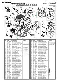
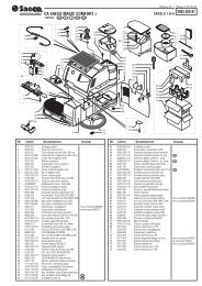
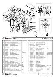
Crathco <strong>Granita</strong> G & MG Series Parts List<br />
ITEM PART DESCRIPTION ITEM PART DESCRIPTION<br />
NO. NO NO. NO<br />
2 90000 Supporting Foot<br />
4 90002 Washer<br />
5 90003 Nut<br />
6 90004 Bushing for Cord<br />
8 90006 Screw<br />
10 90007 General Switch<br />
12 90008 Function Switch (MG Series)<br />
24 90015 Lid Light Switch<br />
29 90391 Lid Merchandiser, city scene<br />
30 90021 Bottom of Lid<br />
31 90022 Bowl, standard<br />
32 90023 Seal for Bowl<br />
38 90027 Drain Tube<br />
39 90028 Nut<br />
40 90029 Screw<br />
41 90030 Hex Head Nut Screw<br />
43 90470 Screw<br />
47 90033 Screw<br />
48 90034 Screw<br />
50 90036 Fuse Holder<br />
51 90471 Fuse, 16 Amp (220V)<br />
60 90043 Dispensing Valve Upper Body<br />
61 90044 Dispensing Valve Spring<br />
63 90046 Dispensing Valve O-ring<br />
74 90048 Thermostat (MG Series)<br />
75 90049 Gear Motor<br />
76 90050 Consistency Control Spring<br />
77 90051 Bushing Consistency Control Spring<br />
78 90052 Nut<br />
79 90053 Consistency Control Pin<br />
80 90054 Limit Microswitch<br />
81 90055 Screw<br />
82 90056 Nut<br />
83 90057 Bushing Spindle Connection<br />
84 90058 Screw<br />
89 90063 Washer for Front Bushing<br />
90 90064 Evaporator<br />
91 90065 Upper Mixing Unit<br />
92 90066 Shaft Seal, Rubber Bell Shaped<br />
94 90068 Securing Nut for Auger<br />
95 90069 Spindle Bushing<br />
97 90071 Drive Shaft<br />
98 90072 Screw<br />
101 90075 Hose Clamp<br />
102 90076 O-ring<br />
103 90077 Washer for Rear Bushing<br />
106 90078 Accumalator<br />
108 90080 Compressor (115/60)<br />
109 90081 Compressor Electrical Parts (115/60)<br />
110 90082 Condenser Fan Motor (115/60)<br />
111 90083 Impeller (60Hz)<br />
112 90084 Control Box Timer (MG Series)<br />
115 90085 Gear Motor Fan (115/60)<br />
116 90086 Screw<br />
125 90102 Lid Socket<br />
270 90464 Filter Drier<br />
272 90129 High Pressure Cutout Switch<br />
274 90005 Cord with Plug AWG14(20A)<br />
277 90465 Filter drier, dual connection<br />
350 90401 Dispensing Valve Handle, Black<br />
351 90402 Handle Securing Pin, Black<br />
352 90403 Dispensing Valve, Lower Body<br />
353 90404 Screw<br />
354 90405 Nut,M5 DIN 934<br />
355 90406 Transformer(IN 115V out 12) G&MG<br />
356 90407 Washer 5X15X1.5<br />
357 90408 Drip Tray Grid Black<br />
358 90409 Black Drip Tray<br />
359 90410 Black Lower Trim<br />
360 90411 Stainless Steel Lower Front Panel<br />
361 90412 Stainless Steel Upper Front Panel<br />
362 90413 Stainless Steel Left Side Panel<br />
363 90414 Black Upper Trim<br />
364 90415 Black Merchandiser Cover<br />
365 90142 Incandescent Light Bulb (BP1156CL)<br />
366 90141 Incandescent Light Socket<br />
367 90418 Center Screw Lid Plug<br />
368 90419 Front Screw Lid Plug<br />
369 90420 Rear Screw Lid Plug<br />
370 90421 Wiring for Black Lid w/Cord<br />
371 90422 Black Cover For Light Bulb<br />
372 90423 Black Evaporator Support<br />
373 90424 Black Cover for Evaporator Support<br />
374 90425 Wiring,PC Control Board (G Series)<br />
375 90426 Black Knob to Secure Bowl<br />
376 90427 Control Board Mounting Plate<br />
377 90428 PC Control Board, Electronic<br />
378 90429 Filter Inlet Air<br />
379 90430 Black Top Tray<br />
380 90431 Screw<br />
381 90432 Back-Lit Merchandiser Panel Bracket<br />
382 90433 Knob Rear Panel<br />
383 90434 O-ring Knob,Rear Panel<br />
384 90435 SS Back Panel<br />
385 90436 Painted Frame<br />
386 90437 Stainless Steel Right Side Panel<br />
387 90438 Screw<br />
388 90439 Screw (Foot)<br />
389 90337 Main Fuse 20A<br />
390 90441 5A Fuse<br />
391 90442 Screw<br />
392 90443 5A Fuse Holder<br />
393 90444 Auger, <strong>Granita</strong> One Piece<br />
394 90445 Bulb Insulator, Rear Merchandiser<br />
395 90446 Screw (Single Pc. Rear Merchandiser)<br />
396 90447 Back-Lit Merchandiser Support (Single Pc.)<br />
397 90448 Bulb Bracket, Rear Merchandiser<br />
398 90449 Back-Lit Cover (Single Pc.)<br />
399 90450 Screw<br />
400 90451 Thermister (G Series)<br />
401 90452 Fan Motor Cover<br />
402 90453 Condenser<br />
403 90454 Condenser Fan Motor Bracket<br />
404 90455 Screw<br />
405 90456 Compressor Mouting Plate<br />
406 90457 Control Box Cover Black<br />
407 90458 Screw<br />
408 90459 Control Board Cover Lock<br />
409 90460 Control Board Cover Key<br />
410 90395 Complete Wiring (MG Series)<br />
411 90132 Timer, Defrost (MG Series)<br />
446 90472 Back-lit Merchandiser, Panel Bracket (Dual Pc.)<br />
306 90392 Rear Merchandiser, City Scene (Single Pc.)<br />
447 90397 Rear Merchandiser Graphic, City Scene (Dual Pc.)<br />
448 90473 Transparent Surface (Dual Pc Rear Merchandiser)<br />
449 90474 Cord with Plug (220V)<br />
450 90475 Transformer (IN 230 OUT 12)<br />
451 90476 Compressor (220/50)<br />
452 90477 Compressor Electrical Parts (220/50)<br />
453 90478 Condensor Fan Motor (220V)<br />
454 90479 Impeller (220/50)<br />
455 90480 Gear Motor Fan (220V)<br />
456 90481 Compressor (220/60)<br />
457 90482 Compressor Electrical Parts (220/60)<br />
90104 Seal Replacement Kit<br />
90106 Brush 1/4" Ceaning<br />
90107 Brush, Valve 1" Cleaning<br />
90110 Shaft Replacement Kit<br />
90112 Food Grade Lubricant<br />
90177 Bowl, 2-gallon<br />
90178 Complete bowl cover G & MG Series<br />
90381 Instruction Manual, G & MG Series<br />
90386 Care & Cleaning Inst., Lam. Card<br />
90468 Control Box Cover Assy. Blk<br />
90469 Complete Dispensing Valve Black<br />
90483 9 ltr. Max Bowl Label<br />
G & MG Series <strong>Granita</strong> <strong>Machine</strong> Page 27
GEAR MOTOR EXPLODED VIEW<br />
Item # Description Part No.<br />
1 ROTOR WITH TWO BEARINGS 90174<br />
4 ARMATURE 90169<br />
6 DRIVE GEAR WITH BEARING 90165<br />
7 IDLER GEAR WITH BEARING 90166<br />
10 OUTPUT SHAFT AND GEAR 90171<br />
13 OUTPUT SHAFT BEARING 90170<br />
19 HOUSING GASKET 90167<br />
41 OUTPUT SHAFT SEAL 90168<br />
Page 28<br />
G & MG Series <strong>Granita</strong> <strong>Machine</strong>
REFRIGERATION DIAGRAM MODEL G SERIES (115V/220V)<br />
Item<br />
CL<br />
DL<br />
CTL<br />
EL<br />
AL<br />
CR<br />
DR<br />
CRT<br />
ER<br />
AR<br />
C & CFM<br />
Description<br />
COMPRESSOR LEFT<br />
DRIER LEFT<br />
CAPILLARY TUBE LEFT<br />
EVAPORATOR LEFT<br />
ACCUMULATOR LEFT<br />
COMPRESSOR RIGHT<br />
DRIVER RIGHT<br />
CAPILLARY TUBE RIGHT<br />
EVAPORATOR RIGHT<br />
ACCUMULATOR RIGHT<br />
CONDENSER AND CONDENSER FAN MOTOR<br />
REFRIGERATION DIAGRAM MODEL MG SERIES (115V)<br />
Item<br />
CL<br />
COL<br />
DL<br />
CTL<br />
EL<br />
AL<br />
CR<br />
COR<br />
DR<br />
CRT<br />
ER<br />
AR<br />
C & CFM<br />
Description<br />
COMPRESSOR LEFT<br />
CUT-OUT LEFT<br />
DRIER LEFT<br />
CAPILLARY TUBE LEFT<br />
EVAPORATOR LEFT<br />
ACCUMULATOR LEFT<br />
COMPRESSOR RIGHT<br />
CUT-OUT RIGHT<br />
DRIVER RIGHT<br />
CAPILLARY TUBE RIGHT<br />
EVAPORATOR RIGHT<br />
ACCUMULATOR RIGHT<br />
CONDENSER AND CONDENSER FAN MOTOR<br />
G & MG Series <strong>Granita</strong> <strong>Machine</strong> Page 29
REFRIGERATION DIAGRAM MODEL MG SERIES (220V)<br />
Item<br />
CL<br />
DL<br />
CTL<br />
EL<br />
AL<br />
CR<br />
DR<br />
CRT<br />
ER<br />
AR<br />
C & CFM<br />
Description<br />
COMPRESSOR LEFT<br />
DRIER LEFT<br />
CAPILLARY TUBE LEFT<br />
EVAPORATOR LEFT<br />
ACCUMULATOR LEFT<br />
COMPRESSOR RIGHT<br />
DRIVER RIGHT<br />
CAPILLARY TUBE RIGHT<br />
EVAPORATOR RIGHT<br />
ACCUMULATOR RIGHT<br />
CONDENSER AND CONDENSER FAN MOTOR<br />
Page 30<br />
G & MG Series <strong>Granita</strong> <strong>Machine</strong>
ELECTRICAL DIAGRAM MODEL - MG SERIES (115)<br />
Item Description Item Description<br />
LB<br />
RB<br />
CO1<br />
CO2<br />
PS<br />
DT<br />
MASL<br />
FSL<br />
RSL<br />
MASR<br />
FSR<br />
RSR<br />
GML<br />
GMFL<br />
TL<br />
GMR<br />
GMFR<br />
LEFT BOWL<br />
RIGHT BOWL<br />
H.P. CUT-OUT SWITCH 1<br />
H.P. CUT-OUT SWITCH 2<br />
POWER SWITCH<br />
DEFROST TIMER<br />
MIXING AUGER SWITCH LEFT<br />
FREEZING SWITCH LEFT<br />
REFRIGERATING SWITCH LEFT<br />
MIXING AUGER SWITCH RIGHT<br />
FREEZING SWITCH RIGHT<br />
REFRIGERATING SWITCH RIGHT<br />
GEAR MOTOR LEFT<br />
GEAR MOTOR FAN LEFT<br />
THERMOSTAT LEFT<br />
GEAR MOTOR RIGHT<br />
GEAR MOTOR FAN RIGHT<br />
TR<br />
CL<br />
RL<br />
SCL<br />
OPL<br />
CR<br />
RR<br />
SCR<br />
OPR<br />
TRANSF<br />
CFM<br />
LLL<br />
LLR<br />
MSL<br />
MSR<br />
TDB<br />
BLL<br />
BLR<br />
THERMOSTAT RIGHT<br />
COMPRESSOR LEFT<br />
COMPRESSOR RELAY LEFT<br />
STARTING CAPACITOR LEFT<br />
OVERLOAD PROTECTOR LEFT<br />
COMPRESSOR RIGHT<br />
COMPRESSOR RELAY RIGHT<br />
STARTING CAPACITOR RIGHT<br />
OVERLOAD PROTECTOR RIGHT<br />
TRANSFORMER<br />
CONDENSER FAN MOTOR<br />
LID LAMP LEFT<br />
LID LAMP RIGHT<br />
MICROSWITCH LEFT<br />
MICROSWITCH RIGHT<br />
TIME DELAY BOARD<br />
BACK LAMP LEFT<br />
BACK LAMP RIGHT<br />
G & MG Series <strong>Granita</strong> <strong>Machine</strong> Page 31
ELECTRICAL DIAGRAM MODEL - MG SERIES (220V)<br />
Item Description Item Description<br />
LB<br />
RB<br />
PS<br />
DT<br />
MASL<br />
FSL<br />
RSL<br />
MASR<br />
FSR<br />
RSR<br />
GML<br />
GMFL<br />
TL<br />
GMR<br />
GMFR<br />
TR<br />
CL<br />
LEFT BOWL<br />
RIGHT BOWL<br />
POWER SWITCH<br />
DEFROST TIMER<br />
MIXING AUGER SWITCH LEFT<br />
FREEZING SWITCH LEFT<br />
REFRIGERATING SWITCH LEFT<br />
MIXING AUGER SWITCH RIGHT<br />
FREEZING SWITCH RIGHT<br />
REFRIGERATING SWITCH RIGHT<br />
GEAR MOTOR LEFT<br />
GEAR MOTOR FAN LEFT<br />
THERMOSTAT LEFT<br />
GEAR MOTOR RIGHT<br />
GEAR MOTOR FAN RIGHT<br />
THERMOSTAT RIGHT<br />
COMPRESSOR LEFT<br />
RL<br />
SCL<br />
OPL<br />
CR<br />
RR<br />
SCR<br />
OPR<br />
TRANSF<br />
CFM<br />
LLL<br />
LLR<br />
MSL<br />
MSR<br />
TDB<br />
BLL<br />
BLR<br />
COMPRESSOR RELAY LEFT<br />
STARTING CAPACITOR LEFT<br />
OVERLOAD PROTECTOR LEFT<br />
COMPRESSOR RIGHT<br />
COMPRESSOR RELAY RIGHT<br />
STARTING CAPACITOR RIGHT<br />
OVERLOAD PROTECTOR RIGHT<br />
TRANSFORMER<br />
CONDENSER FAN MOTOR<br />
LID LAMP LEFT<br />
LID LAMP RIGHT<br />
MICROSWITCH LEFT<br />
MICROSWITCH RIGHT<br />
TIME DELAY BOARD<br />
BACK LAMP LEFT<br />
BACK LAMP RIGHT<br />
Page 32<br />
G & MG Series <strong>Granita</strong> <strong>Machine</strong>
ELECTRICAL DIAGRAM MODEL - G SERIES (115V/220V)<br />
Item Description Item Description<br />
LB<br />
RB<br />
PS<br />
CFM<br />
TRANSF<br />
BLL<br />
BLR<br />
LLL<br />
LLR<br />
B.B. TIMER<br />
CL<br />
RL<br />
SCL<br />
LEFT BOWL<br />
RIGHT BOWL<br />
POWER SWITCH<br />
CONDENSER FAN MOTOR<br />
TRANSFORMER (IN 120V OUT 12V)<br />
BACK LAMP LEFT<br />
BACK LAMP RIGHT<br />
LID LAMP LEFT<br />
LID LAMP RIGHT<br />
CONTROLLER BOARD<br />
COMPRESSOR LEFT<br />
COMPRESSOR RELAY LEFT<br />
STARTING CAPACITOR LEFT<br />
OPL<br />
CR<br />
OPR<br />
GML<br />
GFML<br />
GMR<br />
GMFR<br />
MSL<br />
MSR<br />
CP<br />
ERP<br />
ELP<br />
OVERLOAD PROTECTOR LEFT<br />
COMPRESSOR RIGHT<br />
OVERLOAD PROTECTOR RIGHT<br />
GEAR MOTOR LEFT<br />
GEAR MOTOR FAN LEFT<br />
GEAR MOTOR RIGHT<br />
GEAR MOTOR FAN RIGHT<br />
MICROSWITCH LEFT<br />
MICROSWITCH RIGHT<br />
CONDENSER PROBE<br />
EVAPORATOR RIGHT PROBE<br />
EVAPORATOR LEFT PROBE<br />
G & MG Series <strong>Granita</strong> <strong>Machine</strong> Page 33
Grindmaster® Coffee Grinders and Brewers • Espressimo® Espresso <strong>Machine</strong>s • Crathco® Hot Beverage Dispensers<br />
Crathco® Cold and Frozen Beverage Dispensers • American Metal Ware® Coffee and Tea Systems<br />
Tel (502) 425-4776 • Fax (502) 425-4664 • 1-800-695-4500<br />
P.O. Box 35020 • Louisville, KY 40232 • USA<br />
www.grindmaster.<strong>com</strong> • email: info@grindmaster.<strong>com</strong>