Frigodrink Service manual - Ugolini
Frigodrink Service manual - Ugolini
Frigodrink Service manual - Ugolini

Create successful ePaper yourself
Turn your PDF publications into a flip-book with our unique Google optimized e-Paper software.
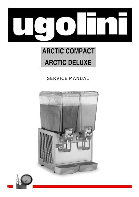
ARCTIC COMPACT<br />
ARCTIC DELUXE<br />
SERVICE MANUAL
ARCTIC COMPACT & DELUXE<br />
2
SERVICE MANUAL 4<br />
USER MANUAL 10<br />
TROUBLE SHOOTING 16<br />
3
ARCTIC COMPACT & DELUXE<br />
1 INTRODUCTION<br />
Like all mechanical products, this machine will require cleaning<br />
and maintenance.<br />
This <strong>Service</strong> Manual contains maintenance guidelines<br />
dedicated to qualified service personnel only.<br />
2 TEMPERATURE CONTROLS<br />
IMPORTANT<br />
Rotating the setting screw of the thermostats completely<br />
counterclockwise it is possible to switch off the<br />
thermostat itself. This will stop the refrigeration only on<br />
single bowl units. On multiple bowls units it is necessary<br />
to switch all the thermostats off in order to stop the<br />
refrigeration.<br />
All the units with12 or 20 litres bowls, both Deluxe and Compact<br />
series, are equipped with one adjustable thermostat for each<br />
bowl. The thermostats are located behind the panel under each<br />
bowl (see figure 1).<br />
IMPORTANT<br />
On multiple bowls units the thermostats are electrically<br />
wired in parallel and they directly drive the compressor.<br />
It is necessary that all the bowls reach the set<br />
temperature to stop the refrigeration (all the thermostats<br />
electrically open). It is enough that only in one bowl the<br />
temperature is higher than the setting to start the<br />
refrigeration (only one thermostat electrically closed).<br />
To adjust temperature on multiple bowls machines it is<br />
necessary to adjust all the thermostats together at the<br />
same setting.<br />
On multiple bowls units independent temperature<br />
adjustment for each bowl is not available.<br />
For Artic Compact 5 and 8 series the situation is the following:<br />
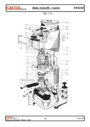
figure 1<br />
It is possible to adjust temperature between 6 °C and 12 °C. On<br />
new machines the temperature is factory preset approx at 8°C.<br />
For temperature adjustment proceed as follows:<br />
- to decrease temperature: rotate the setting screw clockwise.<br />
- to increase temperature: rotate the setting screw<br />
counterclockwise (see figure 2).<br />
Arctic Compact 5-8/1 are equipped with one thermostat to<br />
control the themperature of the bowl.<br />
Arctic Compact 5-8/2 are equipped only with one thermostat to<br />
control the temperature of the bowl at the right.<br />
Arctic Compact 5-8/3 are equipped only with one thermostat to<br />
control the temperature of the central bowl.<br />
Arctic Compact 5-8/4 are equipped with two thermostats to<br />
control the temperature of the first and the third bowl from right.<br />
The thermostats are always located behind the faucet side<br />
panel under the coresponding bowl.<br />
This means that the refrigeration on and off depend from the<br />
setting of the temperature only of the bowls equipped with the<br />
thermostats.<br />
It is possible to set the temperature between 6 °C and 12 °C. On<br />
new machines the temperature is factory preset approx at 8°C.<br />
For temperature adjustment proceed as follows:<br />
- to decrease temperature: rotate the setting screw clockwise.<br />
- to increase temperature: rotate the setting screw<br />
counterclockwise (see figure 2)<br />
Independent temperature setting for each bowl is not possible.<br />
The following table summarizes the number of thermostats<br />
present on each model:<br />
figure 2<br />
MODEL<br />
NUMBER OF<br />
THERMOSTAS<br />
Arctic Compact 5/1 - 8/1 1<br />
Arctic Compact 5/2 - 8/2<br />
Arctic Compact 5/3 - 8/3<br />
Arctic Compact 5/4 - 8/4<br />
1 - RIGHT BOWL<br />
1 - CENTRAL BOWL<br />
2 - FIRST AND THIRD BOWLS<br />
Arctic Compact 12/1 - 20/1 1<br />
Arctic Compact 12/2 - 20/2 2<br />
Arctic Compact 12/3 - 20/3 3<br />
Arctic Compact 12/4 - 20/4 4<br />
Arctic Deluxe 12/1 - 20/1 1<br />
Arctic Deluxe 12/2 - 20/2 2<br />
Arctic Deluxe 12/3 - 20/3 3<br />
Arctic Deluxe 12/4 - 20/4 4<br />
4
3 PUMPS<br />
Arctic Deluxe series dispensers are equipped with spray<br />
pumps. Each pump is magnetically driven by an independent<br />
electric motor.<br />
These machines are equipped with one Main Switch to power<br />
ON and OFF refrigeration and with one Pump Switch for each<br />
bowl (see user <strong>manual</strong> for controls details).<br />
Spray pumps are suitable for a large variety of products but it is<br />
better not to spray coffee, tea, natural juices or other beverages<br />
that can foam. To avoid spray on these machines it is necessary<br />
to replace the original impeller with a different one (grey impeller<br />
pn 33900-01201) and to remove the spray tube from the bowl.<br />
In addition the original bowl can be replaced with a dedicated<br />
one (pn 22900-00010 or 22900-04810) to perform even more<br />
gentle agitation.<br />
Arctic Compact series dispensers are equipped with<br />
submerged pumps. On double machines the pumps are driven<br />
by only one motor through a transmission belt and three pulleys.<br />
This motor also works as a fan. On triple machines two pumps<br />
are driven by one motor with the same system of double units<br />
and the third is driven by a single motor. On four bowls machies<br />
the pumps are driven by two motors (see figure 3).<br />
The following table summarizes all the available bowls:<br />
PART<br />
NUMBER<br />
BOWLS<br />
CAPACITY<br />
[litres]<br />
MIXING<br />
SYSTEM<br />
22900-01900 5 SPRAY<br />
22900-01910 5 SUBMERGED<br />
22900-02000 8 SPRAY<br />
22900-02010 8 SUBMERGED<br />
22900-00000 12 SPRAY<br />
22900-00010 12 SUBMERGED<br />
22900-04800 20 SPRAY<br />
22900-04810 20 SUBMERGED<br />
And the following one specifies all the available spray tubes:<br />
PART<br />
NUMBER<br />
BOWLS<br />
CAPACITY<br />
[litres]<br />
22900-00202 5<br />
22900-00203 8<br />
22900-00201 12<br />
22900-00200 20<br />
Combined configuration can be realized for particular needings.<br />
3. 1 IMPELLERS<br />
The impeller must spin freely on its pivot to perform efficient<br />
mixing and cooling. For this purpose keep clean both the<br />
impeller and the pivot from traces of sugar, pulp or other. If<br />
necessary, lube the parts with food grade lubricant.<br />
A self-lubricating washer is moulded into the bottom of the<br />
impeller. Regularly check this part and, if worn, replace the<br />
impeller with a new one (see figure 4).<br />
figure 3<br />
These machines are equipped only by one Main Switch to<br />
power ON and OFF all the functions, refrigeration and pumps.<br />
Submerged pumps are suitable for almost all kind of beverages<br />
and particularly for coffee, tea, natural juices or other beverages<br />
that can foam. In case of need it is possible to equip Arctic<br />
Compact dispensers with spray pumps replacing the impellers<br />
(pn 33900-01204 or 33900-01205), the bowls (pn 22900-01900,<br />
22900-02000, 22900-00000 and 22900-04800) and installing<br />
the spray tubes.<br />
The following table summarizes all the available impellers:<br />
PART<br />
NUMBER<br />
COLOUR<br />
BOWLS<br />
CAPACITY<br />
[litres]<br />
MIXING<br />
SYSTEM<br />
VOLATGE<br />
33900-01200 WHITE 12, 20 SPRAY 230V 50HZ, 240V 50HZ<br />
33900-01201 GREY 5, 8, 12, 20 SUBMERGED 230V 50HZ, 240V 50HZ<br />
115V 60HZ, 220V 60HZ<br />
33900-01204 BLUE 5, 8<br />
12, 20<br />
SPRAY<br />
SPRAY<br />
230V 50HZ, 240V 50HZ<br />
115V 60HZ, 220V 60HZ<br />
33900-01205 RED 5, 8 SPRAY 115V 60HZ, 220V 60HZ<br />
5<br />
figure 4<br />
3. 2 MAGNETIC COUPLING<br />
The impellers are magnetic coupled with their respective<br />
motors. The magnetic gap is factory preset and does not require<br />
to be adjusted. In case of loss of magnetic lock, one or more of<br />
the following problems can be present: bent pump motor bracket<br />
due to a transport shock, impeller improper spinning due to<br />
worn, damaged or dirty parts.<br />
3. 3 NOISY IMPELLERS<br />
In case of noisy impellers, it is necessary first of all to remove<br />
them from the pivots and power the unit on. If the noise is still<br />
present it is necessary to power the unit off, unplug it and<br />
remove the panels in order to check the pumps motors<br />
assemblies. Possible causes of noise can be the following:<br />
faulty electric motor, improper magnetic alignment due to a bent
ARCTIC COMPACT & DELUXE<br />
bracket, fan blade not rotating free from obstacles or some lose<br />
component vibrating during machine working.<br />
On Arctic Compact with multiple bowls it is necessary also to<br />
remove the transmission belt from the pulleys and power on the<br />
unit. If the noise is still present the cause can be the electric<br />
motor once again. Otherwise, if the noise is not present<br />
anymore, it is necessary to remove the magnetic pulleys<br />
assemblies and check for the integrity of their ball bearings. If<br />
necessary replace the entire magnetic pulley assembly.<br />
If, removing the impellers, the noise is not present anymore it<br />
means that the cause of can be in the impellers or in the<br />
magnetic coupling. Check for worn impellers and if necessary<br />
replace them. Clean the impellers and the pivots and if<br />
necessary lubricate them with food grade lubricant. Install the<br />
impellers and put some water into the bowls. If the noise do not<br />
disappear it is necessary to check once again the pump motor<br />
bracket planarity.<br />
figure 5<br />
5 SLOW MIXING SYSTEM<br />
IMPORTANT<br />
The impellers are designed to spin always submerged<br />
and wet. It is very important to avoid to have them<br />
spinning dry to prevent worn out. For this reason on<br />
Arctic Deluxe always switch off pump of empty bowls<br />
and on Arctic Compact remove the impeller of empty<br />
bowls or fill them with water.<br />
The dispensers of Arctic Deluxe series are available also with<br />
slow mixers. Two kind of slow mixers are available: one with<br />
magnetic driving (A) and the other with mechanic driving (B).<br />
The first one is suitable for delicate drinks like tea or coffee while<br />
the other one is suitable also for thick drinks (see figure 6).<br />
4 FAUCETS<br />
Two different faucets are available both for Arctic Deluxe and<br />
Arctic Compact series: pinch tube faucet and stainless steel<br />
gravity faucet.<br />
4. 1 PINCH TUBE FAUCET<br />
This faucet is suitable for all kind of products, liquid or thick, with<br />
or without pulp or other solid particles. In case of dripping, it is<br />
necessary to drain the product out of the bowl, remove the pinch<br />
tube, clean it with fresh water and check for wear on it. If<br />
necessary, replace it with a new one.<br />
4. 2 STAINLESS STEEL GRAVITY FAUCET<br />
figure 6<br />
In case of magnetic slow mixer improper rotation, the cause can<br />
be a faulty drive motor, a magnetic mixer that can’t freely rotate<br />
on its pivot or ice on the evaporator caused by very low level of<br />
product into the bowl.<br />
In case of direct slow mixer improper rotation the cause can be<br />
a foulty motor or an excessive thickness of the drink.<br />
6 REFRIGERANT CIRCUIT SERVICE<br />
This faucet is suitable for liquid product without pulps or other<br />
solid particles. In case of dripping, it is necessary to drain the<br />
product out of the bowl, remove the stainless steel piston, clean<br />
it with fresh water and check for wear of the rubber gasket. If<br />
necessary, replace it with a new one. It is also necessary to<br />
clean the piston housing in the bottom of the bowl and check for<br />
the integrity of the rim around the piston hole (see figure 5).<br />
6<br />
6. 1 CHECKING FOR REFRIGERANT LEAKS<br />
The following procedure is the recommended approach to<br />
systematically inspect the entire system for refrigerant leaks<br />
NOTE: when using refrigerant detector, follow along the bottom
side of the copper tubing since the refrigerant gas is heavier<br />
than air. Where copper tubing is protected by an insulating<br />
jacket, check for leaks at both ends of each jacket section.<br />
.<br />
figure 8)<br />
figure 7<br />
Referring to the diagram (see figure 7), perform the following<br />
steps:<br />
1 Start inspection at the high pressure line of the compressor.<br />
Check around the soldered connection.<br />
2 Follow the copper tubing to the condenser and check<br />
around the soldered connections at the top and bottom of the<br />
condenser.<br />
3 Check also along the copper curves on both sides of<br />
condenser.<br />
4 Follow the copper tubing to the evaporators, checking<br />
around the soldered connections of dryer.<br />
5 Remove mixer motors and check the inlet (capillary) and<br />
outlet (suction) tubing.<br />
6 Check the copper tubing all the way back to the<br />
compressor.<br />
7 Check around the low side connections of the compressor<br />
suction and process tubes.<br />
6. 3 EVACUATING<br />
figure 8<br />
Always install a brand new liquid line filter dryer before<br />
evacuating.<br />
1 Connect the REF port of the gauge set to the charging unit.<br />
2 Connect the VAC port of the gauge set to the vacuum pump<br />
and open the VAC valve.<br />
3 Open the line valve of the charging unit and, for a while,<br />
also the REF valve, so as to purge air from the REF hose.<br />
4 Open the LOW valve of the gauge set and turn on the<br />
vacuum pump for a minimum of half an hour.<br />
5 While the pump is running, close the VAC valve once a<br />
vacuum has been established.<br />
6 Turn off the vacuum pump.<br />
6. 4 CHARGING<br />
IMPORTANT<br />
To check for a leak in the low side of the system, it is<br />
advisable to have the evaporators at least at ambient<br />
temperature.<br />
If a leak has been detected, seal it and make a new refrigerant<br />
charge as per instructions in the following paragraphs.<br />
6. 2 DISCHARGING<br />
1 Remove the dispenser panels.<br />
2 If not present install a charging valve on the compressor<br />
process tube.<br />
3 Remove the screw cap from the compressor process tube.<br />
4 Connect the process tube to the LOW part of the gauge set.<br />
5 Connect the VAC port of the gauge set to an adequate<br />
approved gas recovery system.<br />
ATTENTION<br />
The refrigerant gas could be highly acid and toxic.<br />
6 Open the LOW and VAC valves and recover the refrigerant.<br />
7 Once the recovery operation is completed, close the LOW<br />
and VAC valves and disconnect the recovery system.(see<br />
7<br />
The gauge set is usually with four ports and four valves (see<br />
figure 8). This is the easiest option to be found in the market<br />
since it allows the charging through both low and high side of the<br />
system. Our refrigeration systems are manufactured so as to be<br />
chargeable through the compressor process tube only (low<br />
side): thus, the HI port is never mentioned nor used in the<br />
following procedure and therefore the HI valve must be kept<br />
closed.<br />
1 Determine how many ounces/grams should be filled by the<br />
charging unit. This information can be found on the dispenser<br />
data plate.<br />
2 Remove bowls and mixers from the dispenser.<br />
3 Plug in the dispenser and turn on the power switch.<br />
4 Open the line valve of the charging unit.<br />
5 Open the REF valve very slowly so as to allow the<br />
refrigerant to be pulled into the system as a gas.<br />
6 When the amount of refrigerant listed on the data plate has<br />
been used, the system is charged. Close the REF valve and<br />
the charging unit line valve and allow the compressor to run few<br />
minutes.<br />
7 Ensure that all evaporator plates are covered with frost.<br />
8 Close the LOW valve, disconnect the LOW hose from the<br />
compressor process tube and tighten the screw cap.<br />
The following table reports the suction and discharge pressures<br />
of the machines with the different refrigerants.<br />
They must be verified under the following conditions:<br />
Ambient temperature: 32 °C<br />
Product temperature in the bowls: 5 °C<br />
Evaporation temperature approx -5 °C<br />
Condensation temperature approx 50°C.
ARCTIC COMPACT & DELUXE<br />
Refrigerant<br />
Suction (low)<br />
pressure<br />
Discharge (high)<br />
pressure<br />
R134a 1,43 bar 12,17 bar<br />
R22 3,20 bar 18,39 bar<br />
R404a 4,10 bar 21,93 bar<br />
6. 5 COMPRESSOR BURN-OUT<br />
To determine if a burn-out has occurred, perform the following<br />
steps:<br />
1 Disconnect the unit from power source.<br />
2 Remove wiring from the compressor terminals.<br />
3 Using an ohmmeter, check for ground between the<br />
terminals and the compressor housing. If a reading exists, the<br />
compressor has shorted to ground.<br />
In this case compressor must be replaced as per following<br />
steps:<br />
4 Recover the refrigerant using an approved refrigeration<br />
recovery system as per DISCHARGING instructions.<br />
5 Remove the burned-out compressor.<br />
6 Correct the system fault which caused the burn-out. Check<br />
the condition of the capacitor(s) and compressor relay.<br />
7 Install a new compressor and liquid line filter dryer.<br />
8 Evacuate and charge the system as per EVACUATING and<br />
CHARGING instructions.<br />
figure 9<br />
7 ROUTINE MAINTENANCE<br />
DAILY<br />
Inspect the machine for signs of product leaks past seals and<br />
gaskets. If proper assembly does not stop leaks around seal or<br />
gaskets, check for improper lubrication, worn or damaged parts.<br />
Replace parts as needed with original spare parts from the<br />
supplier.<br />
WEEKLY<br />
Clean and sanitize the machine following the procedures<br />
illustrated on the Operator's Manual of the unit. Check for worn<br />
impellers, bowl gaskets, faucet pinch tubes or stainless steel<br />
piston gaskets. Replace parts as needed with original spare<br />
parts from the supplier.<br />
MONTHLY<br />
Clean all internal components, primarily the condenser, using<br />
compressed air, vacuum or a soft brush.<br />
To clean these internal parts, unplug the unit and remove the<br />
panels. Condenser fins are very sharp. Use extreme caution<br />
when cleaning.<br />
On Arctic Deluxe dispensers the condenser is located on the<br />
back of the unit and air flow is from back to sides (A). To clean<br />
the condenser it is necessary to remove the back panel.<br />
On Arctic Compact dispensers the condenser is always<br />
located on the back of the unit but air flow if from sides to back<br />
(B). To clean the condenser it is necessary to remove the faucet<br />
side panel and to clean it from the inside of the unit (see figure<br />
5).<br />
8
ARCTIC COMPACT & DELUXE<br />
The following key operation procedures, extracted from the<br />
Operator’s Manual, are quoted here too so that service<br />
personnel may help end users to achieve the best<br />
performances and results.<br />
1 TECHNICAL CHARACTERISTICS<br />
ARCTIC COMPACT 5/8 lt<br />
1/5<br />
1/8<br />
2/5<br />
2/8<br />
3/5<br />
3/8<br />
4/5<br />
4/8<br />
Transparent removable bowls n 1 2 3 4<br />
Capacity of each bowl, approx. l 5<br />
8<br />
Dimensions:<br />
width cm 18 25 37 50<br />
depth cm 40 40 40 40<br />
height<br />
5 lt<br />
8 lt<br />
cm 55<br />
63<br />
55<br />
63<br />
55<br />
63<br />
55<br />
63<br />
Net weight, approx.<br />
Gross weight, approx.<br />
5 lt<br />
8 lt<br />
5 lt<br />
8 lt<br />
kg 13<br />
13<br />
kg 15<br />
15<br />
5<br />
8<br />
15<br />
17<br />
17<br />
19<br />
5<br />
8<br />
21<br />
21<br />
23<br />
23<br />
5<br />
8<br />
23<br />
23<br />
26<br />
26<br />
Adjustable thermostats n 1 1 1 2<br />
ARCTIC COMPACT 12/20 lt<br />
1/12<br />
1/20<br />
2/12<br />
2/20<br />
3/12<br />
3/20<br />
4/12<br />
4/20<br />
Transparent removable bowls n 1 2 3 4<br />
Capacity of each bowl, approx. l 12<br />
20<br />
Dimensions:<br />
12<br />
20<br />
12<br />
20<br />
12<br />
20<br />
width cm 18 36 54 72<br />
depth cm 47 47 47 47<br />
height<br />
12 lt<br />
20 lt<br />
cm 61<br />
71<br />
61<br />
71<br />
61<br />
71<br />
61<br />
71<br />
Net weight, approx.<br />
Gross weight, approx.<br />
12 lt<br />
20 lt<br />
12 lt<br />
20 lt<br />
kg 20<br />
22<br />
kg 22<br />
25<br />
24<br />
32<br />
28<br />
36<br />
36<br />
42<br />
40<br />
46<br />
44<br />
55<br />
49<br />
59<br />
Adjustable thermostats n 1 2 3 4<br />
IMPORTANT<br />
Read electrical ratings written on the data plate of the<br />
individual units; the data plate is adhered on the dispensing<br />
side panel of the unit, just behind the drip tray (the<br />
right side drip tray in multiple bowl models). The serial<br />
number of the unit (preceded by the symbol #) is adhered<br />
just below the right bowl. Data plate specifications will<br />
always supersede the information in this <strong>manual</strong>.<br />
Specifications are subject to change without notice.<br />
2 INTRODUCTION<br />
Please read all sections of this <strong>manual</strong> thoroughly to familiarize<br />
yourself with all aspects of the unit.<br />
Like all mechanical products, this machine will require cleaning<br />
and maintenance. Besides, dispenser working can be<br />
compromised by operator’s mistakes during disassembly and<br />
cleaning. It is strongly recommended that personnel responsible<br />
for the equipment’s daily operations, disassembly, cleaning,<br />
sanitizing and assembly, go through these procedures in order<br />
to be properly trained and to make sure that no<br />
misunderstandings exist.<br />
3 INSTALLATION<br />
1 Remove the corrugate container and packing materials and<br />
keep them for possible future use.<br />
IMPORTANT<br />
ARCTIC DELUXE 12/20 lt<br />
1/12<br />
1/20<br />
2/12<br />
2/20<br />
3/12<br />
3/20<br />
4/12<br />
4/20<br />
Transparent removable bowls n 1 2 3 4<br />
Capacity of each bowl, approx. l 12<br />
20<br />
Dimensions:<br />
12<br />
20<br />
12<br />
20<br />
12<br />
20<br />
width cm 18 36 54 72<br />
depth cm 47 47 47 47<br />
height<br />
12 lt<br />
20 lt<br />
cm 57<br />
67<br />
57<br />
67<br />
57<br />
67<br />
57<br />
67<br />
Net weight, approx.<br />
Gross weight, approx.<br />
12 lt<br />
20 lt<br />
12 lt<br />
20 lt<br />
kg 20<br />
22<br />
kg 22<br />
25<br />
24<br />
32<br />
28<br />
36<br />
36<br />
42<br />
40<br />
46<br />
44<br />
55<br />
49<br />
59<br />
Adjustable thermostats n 1 2 3 4<br />
Hermetic compressor<br />
Air-cooled condenser<br />
Overload protector<br />
Noise level lower than 70 dB (A)<br />
10<br />
When handling the machine never grasp it by the bowls<br />
or by the evaporator cylinders. The manufacturer refuses<br />
all responsibilities for possible damages which may<br />
occur through incorrect handling.<br />
2 Inspect the uncrated unit for any possible damage. If<br />
damage is found, call the delivering carrier immediately to file a<br />
claim.<br />
3 Install the unit on a counter top that will support the combined<br />
weight of dispenser and product bearing in mind what is<br />
stated in the preceding point 1 IMPORTANT warning.<br />
4 A minimum of 15 cm (6”) of free air space all around the unit<br />
should be allowed to guarantee adequate ventilation.<br />
5 Ensure that the legs are screwed tightly into the base of the<br />
machine.<br />
Replace the standard legs originally installed with the 100 mm<br />
(4”) legs whenever they are provided with the unit.<br />
6 Before plugging the unit in, check if the voltage is the same<br />
as that indicated on the data plate. Plug the unit into a grounded,<br />
protected single phase electrical supply according to the<br />
applicable electrical codes and the specifications of your<br />
machine. Should you prefer to connect the unit directly to the<br />
mains, connect the supply cord to a 2-pole wall breaker, whose
contact opening is at least 3 mm. Do not use extension cords.<br />
ATTENTION<br />
Failure to provide proper electrical ground according to<br />
applicable electrical codes could result in serious shock<br />
hazard.<br />
7 The unit doesn’t come presanitized from the factory. Before<br />
serving products, the dispenser must be disassembled, cleaned<br />
and sanitized according to this handbook instructions<br />
(chapter 5.3 CLEANING AND SANITAZING PROCEDURES).<br />
IMPORTANT<br />
Install the dispenser so that the plug is easily accessible.<br />
over the bowls.<br />
5 Set the control switches as shown in chapter<br />
5.1 DESCRIPTION OF CONTROLS.<br />
6 The dispenser must always run with the covers installed to<br />
prevent a possible contamination of the product.<br />
7 Always leave the dispenser on, as the refrigeration stops<br />
automatically when the beverage reaches the dispensing temperature.<br />
The mixing devices will continue to turn.<br />
8 To maintain a high standard of flavour, keep refrigeration<br />
and mixing devices on during the night when beverage is in the<br />
bowl.<br />
IMPORTANT<br />
Operate the dispenser with food products only.<br />
9 On Arctic Deluxe series machines equipped with lighted top<br />
covers it is necessary to turn the cover for 180 degrees to<br />
switch light off. (see figure 1)<br />
4 TO OPERATE SAFELY<br />
1 Do not operate the dispenser without reading this operator’s<br />
<strong>manual</strong>.<br />
2 Do not operate the dispenser unless it is properly grounded.<br />
3 Do not use extension cords to connect the dispenser.<br />
4 Do not operate the dispenser unless all panels are restrained<br />
with screws.<br />
5 Do not obstruct air intake and discharge openings: 15 cm<br />
(6”) minimum air space all around the dispenser.<br />
6 Do not put objects or fingers in panels louvers and faucet<br />
outlet.<br />
7 Do not remove bowls, augers and panels for cleaning or<br />
routine maintenance unless the dispenser is disconnected from<br />
its power source.<br />
ATTENTION<br />
In case of damages, the power cord must be replaced by<br />
qualified personnel only in order to prevent any shock<br />
hazard.<br />
8 This unit is not meant to be used outside.<br />
9 This unit is not to be installed in areas subject to waterspouts..<br />
10 Do not use water-jets to clean the unit.<br />
11 This unit can work in a room temperature range between<br />
+5° and +32°C.<br />
5 OPERATING PROCEDURES<br />
figure 1<br />
5. 1 DESCRIPTION OF CONTROLS<br />
The dispenser is equipped with a power switch and each bowl is<br />
operated by a mixing device switch.<br />
Their functions are as follows:<br />
Power switch<br />
0 position : Power is turned OFF to all<br />
functions.<br />
I position :<br />
On Arctic Deluxe series this<br />
position operates the fan<br />
motor and makes the mixing<br />
devices suitable to be turned<br />
on by relevant switches.<br />
On arctic Compact series this<br />
position operates all the<br />
funtions of the dispenser.<br />
Mixing device switch (Arctic Deluxe series only)<br />
1 Clean and sanitize the unit according to the instructions in<br />
this <strong>manual</strong>. See chapter 5.3 CLEANING AND SANITIZING<br />
PROCEDURES.<br />
2 Fill the bowls with product to the maximum level mark. Do<br />
not overfill.<br />
The exact quantity of product (expressed as liters and gallons)<br />
is shown by marks on the bowl.<br />
3 In case of products to be diluted with water, potable water,<br />
pour water into bowl first, then add correct quantity of product.<br />
In case of natural squashes, it is advisable to strain them, in<br />
order to prevent pulps from obstructing the faucet outlet.<br />
4 Install the covers and check that they are correctly placed<br />
11<br />
0 position : OFF.<br />
I position : Mixing device runs.<br />
To operate the dispenser<br />
1 Set power switch to I position.<br />
2 Set mixing device switch(es) to I position.
ARCTIC COMPACT & DELUXE<br />
5. 2 OPERATION HELPFUL HINTS<br />
take the pinch tube off from its seat (2) (see figure 3).<br />
1 The length of time for cooling down the product is governed<br />
by many variables, such as ambient temperature and beverage<br />
initial temperature.<br />
2 To shorten product cooling down time and increase productivity,<br />
it is advisable to pre-chill the product to be used in the<br />
dispenser.<br />
3 To shorten product cooling down time and increase productivity,<br />
the bowl should be refilled after the product level drops<br />
lower than half and at the start of each day.<br />
4 The dispenser must be able to emit heat.<br />
In case it seems excessive, check that no heating source is<br />
close to the unit and air flow through the slotted panels is not<br />
obstructed by wall or boxes. Allow at least 15 cm (6”) of free<br />
clearance all around the dispenser.<br />
In any case if the product in the bowls is cold the unit is running<br />
properly.<br />
5 How to reset beverage temperature:to reset beverage temperature<br />
please apply to a technician.<br />
The proper temperature is preset at the factory.<br />
5. 3 CLEANING AND SANITIZING<br />
PROCEDURES<br />
figure 3<br />
6 Gravity faucet: extract the piston and then remove the<br />
dispensing handle (see figure 4).<br />
Cleaning and sanitizing of the dispenser are recommended to<br />
guarantee the conservation of the best product taste and the<br />
highest unit efficiency. This section is a procedural guideline<br />
only and is subject to the requirements of the local Health<br />
Authorities.<br />
Prior to the disassembly and cleaning, the machine must be<br />
emptied of product.<br />
5. 3. 1 DISASSEMBLY<br />
ATTENTION<br />
Before any disassembly and/or cleaning procedure make<br />
sure that the dispenser is disconnected from its power<br />
source by unplugging it or switching off the 2-pole wall<br />
breaker.<br />
1 Remove cover from the bowl.<br />
2 Remove the empty bowl by pulling lever (1) and lifting its<br />
front side (faucet side) up and off bowl gasket (see figure 2).<br />
figure 4<br />
7 Slide drip tray out and empty it.<br />
5. 3. 2 CLEANING<br />
IMPORTANT<br />
Do not attempt to wash any machine components in a<br />
dishwasher.<br />
ATTENTION<br />
Before any disassembly and/or cleaning procedure make<br />
sure that the dispenser is disconnected from its power<br />
source.<br />
figure 2<br />
3 Remove the bowl gasket.<br />
4 Remove the pump impeller from its location.<br />
5 Pinch tube faucet: push the dispensing handle (1) and<br />
12<br />
1 Prepare at least two gallons of a mild cleaning solution of<br />
warm (45-60 °C 120-140 °F) potable water and dishwashing<br />
detergent. Do not use abrasive detergent.<br />
Important: if present, follow label directions, as too strong a<br />
solution can cause parts damage, while too mild a solution will
not provide adequate cleaning.<br />
its gasket (see figure 6).<br />
IMPORTANT<br />
In order to prevent any damages to the dispenser, use<br />
only a detergent suitable with plastic parts.<br />
2 Using a brush, suitable for the purpose, thoroughly clean all<br />
disassembled parts in the cleaning solution.<br />
ATTENTION<br />
When cleaning the machine, do not allow excessive<br />
amounts of water around the electrically operated components<br />
of the unit. Electrical shock or damage to the<br />
machine may result.<br />
figure 6<br />
4 Fit the bowl gasket to the evaporator. Note: the larger brim<br />
of the gasket must face against the drip plate (see figure 7).<br />
3 Do not immerse the lighted top covers in liquid. Wash them<br />
apart with the cleaning solution. Carefully clean their undersides.<br />
4 In the same manner clean the evaporator plate(s) using a<br />
soft bristle brush.<br />
5 Rinse all cleaned parts with cool clean water.<br />
5. 3. 3 SANITIZING<br />
Sanitizing should be performed immediately prior to<br />
starting the machine. Do not allow the unit to sit for<br />
extended periods of time after sanitization.<br />
1 Wash hands with a suitable antibacterial soap.<br />
2 Prepare at least two gallons of a warm (45-60 °C 120-<br />
140 °F) sanitizing solution (100 PPM available chlorine concentration<br />
or 1 spoon of sodium hypoclorite diluted with two litres of<br />
water) according to your local Health Codes and manufacturer’s<br />
specifications.<br />
3 Place the parts in the sanitizing solution for five minutes.<br />
4 Do not immerse the lighted top covers in liquid. Carefully<br />
wash their undersides with the sanitizing solution.<br />
5 Place the sanitized parts on a clean dry surface to air dry.<br />
6 Wipe clean all exterior surfaces of the unit. Do not use abrasive<br />
cleaner.<br />
5. 3. 4 ASSEMBLY<br />
1 Slide the drip tray into place.<br />
2 Pinch tube faucet: push the dispensing handle (1) and<br />
insert the pinch tube into its vertical seat in the bowl bottom(2).<br />
Lightly pull the pinch tube end downwards til it is well arranged<br />
(3) (see figure 5).<br />
figure 5<br />
3 Gravity faucet: install the faucet handle and the piston with<br />
13<br />
figure 7<br />
5 Place bowl on the unit. Wet the gasket for ease of insertion.<br />
Please take care that the hook on the backside of the bowl be<br />
inserted properly in its seat on the upper drip plate. (see figure<br />
8).<br />
figure 8<br />
6 Use fresh product to chase any remaining sanitizer from the<br />
bowl(s). Drain this solution. Do not rinse out the machine.<br />
5. 4 IN-PLACE SANITIZATION<br />
Daily: The In-Place Sanitization prior to starting the machine<br />
may be performed, if needed, only as further precaution, in<br />
addition to the Disassembled Parts Sanitization described<br />
before, but never in lieu of it.<br />
1 Prepare two gallons of a warm (45-60°C, 120-140 °F) sanitizing<br />
solution (100 PPM available chlorine concentration or 1<br />
spoon of sodium hypoclorite diluted with two litres of water)<br />
according to your local Health Codes and manufacturer’s specifications.<br />
2 Pour the solution into the bowl(s).<br />
3 Using a brush suitable for the purpose, wipe the solution on<br />
all surfaces protruding above the solution-level and on the<br />
underside of the top cover(s).<br />
4 Install the top cover(s) and operate the unit. Allow the solution<br />
to agitate for about two minutes. Drain the solution out of<br />
the bowl(s).<br />
5 Use fresh product to chase any remaining sanitizer from the<br />
bowl(s). Drain this solution. Do not rinse out the machine.
ARCTIC COMPACT & DELUXE<br />
6 ROUTINE MAINTENANCE<br />
1 Replacement of lighted top cover bulbs (see figure 9) :<br />
- Remove the fixing screws placed in the upper part of the top<br />
cover,<br />
- remove the lower part and replace the bulbs (using a 24-<br />
28V 21W max bulbs).<br />
- Reassemble the top cover and replace the fixing screws.<br />
figure 9<br />
2 Daily: inspect the machine for signs of product leaks past<br />
seals and gaskets. If proper assembly does not stop leaks<br />
around seals or gaskets, check for improper lubrication, worn<br />
or damaged parts. Replace parts as needed with original spare<br />
parts from the supplier.<br />
6. 1 MAINTENANCE (TO BE CARRIED OUT BY<br />
QUALIFIED SERVICE PERSONNEL ONLY)<br />
Montly: clean all internal components, primarily the condenser,<br />
using compressed air.<br />
To clean these internal parts, unplug the unit or switch off the 2-<br />
pole wall breaker, then remove front panel (dispensing side).<br />
Condenser fins are very sharp. Use extreme caution when<br />
cleaning.<br />
14
ARCTIC COMPACT & DELUXE<br />
The following Spare Parts List, extracted from the Operator’s Manual, are quoted here too for general reference only.<br />
To order spare parts please make refernece to the Spare Part List included in the Operator’s Manual supplied with each<br />
dispenser.<br />
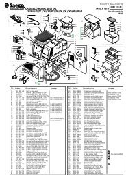
SPARE PARTS LIST ARCTIC COMPACT 5/8 LT MODEL<br />
16
4 22800-21900 Faucet piston 32 33900-01052 Pulley, magnet and spacer assembly<br />
5 10028-02500 Faucet gasket 33 22800-05100 Switch cap<br />
7 22900-02010 8 It bowl 34 22900-03602 Belt<br />
8 21703-00000 Pinch tube 35 22800-02201 Driving pulley<br />
9 22900-01910 5 It bowl 36 22800-04800 Motor bracket<br />
11 10029-00000 Picture 37 22800-18921 Fan/pump motor for 1 bowl<br />
12 22900-00500 Push handle 37A 22900-03011 Fan/pump motor for 2, 4 bowls<br />
13 22900-00800 Faucet cover 38 Fan<br />
14 22900-00501 Push handle 39 Relay<br />
15 22800-02600 Faucet spring 40 Overload protector<br />
16 22900-01300 8 It bowl cover 41 22800-12700 Terminal block cover<br />
17 22900-01300 5 It bowl cover 42 22800-05500 Terminal block with cable clamp<br />
21 22800-17200 Bowl gasket 43 22800-10000 Rubber leg<br />
22 33900-01201 Impeller 44 Dispensing side panel<br />
23 22900-00600 Central pivot 45 Drip tray cover<br />
24 22040-00000 Central pivot OR 46 Drip tray<br />
27 21087-00000 Thermostat 47 33800-00803 Motor magnet for 1, 3 bowls<br />
29 10554-45000 Clip 48 22800-04800 Motor bracket<br />
30 Cabinet 49 22800-04706 Pump motor 3 bowls<br />
31 21125-00000 Switch<br />
Please order what printed on piece See table<br />
<br />
1/.. 2/.. 3/.. 4/..<br />
30 22900-03210 22900-03211 22900-03212 22900-03213<br />
38 22900-00403 22900-00401 22900-00401 22900-00401<br />
44 22900-03110 22900-03111 22900-03112 22900-03113<br />
45 22800-00500 22800-00510 22800-00510 22800-00510<br />
46 22800-00602 22800-00611 22800-00611 22800-00611<br />
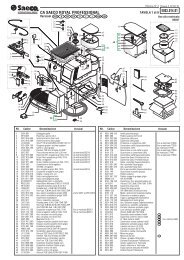
WIRING DIAGRAM ARCTIC COMPACT 5/8 LT MODEL<br />
1/5-8 - 2/5-8 - 3/5-8<br />
1 Switch<br />
2 Thermostat<br />
3-5 Pump/mixer<br />
4 Compressor<br />
4/5-8<br />
1 Switch<br />
2-3 Thermostat<br />
4-6 Pump/mixer<br />
5 Compressor<br />
17
ARCTIC COMPACT & DELUXE<br />
The following Spare Parts List, extracted from the Operator’s Manual, are quoted here too for general reference only.<br />
To order spare parts please make refernece to the Spare Part List included in the Operator’s Manual supplied with each<br />
dispenser.<br />
SPARE PARTS LIST ARCTIC COMPACT 12/20 LT MODEL<br />
18
1 22900-00100 20 It bowl cover 22 22800-05100 Switch cap<br />
2 22900-00100 12 It bowl cover 23 33900-01051 Pulley, magnet and spacer assembly<br />
3 22900-04810 20 It bowl 24 22900-03601 Belt<br />
4 22900-00010 12 It bowl 25 22800-02201 Driving pulley<br />
5 22800-02600 Faucet spring 26 22800-04800 Motor bracket<br />
6 22800-17200 Bowl gasket 27 22800-18921 Fan/pump motor for 1 bowl<br />
7 33900-01201 Impeller 27A 22900-03001 Fan/pump motor for 2, 4 bowls<br />
8 22900-00700 Plastic I-beam for connection 28 Fan<br />
9 22900-00600 Central pivot 29 Relay<br />
10 22040-00000 Central pivot OR 30 Overload protector<br />
11 22900-03051 Capacitor 31 22800-12700 Terminal block cover<br />
12 10554-45000 Clip 32 22800-05500 Terminal block with cable clamp<br />
13 22800-21900 Faucet piston 33 33800-00803 Motor magnet for 1, 3 bowls<br />
14 10028-02500 Faucet gasket 34 22800-04800 Motor bracket<br />
15 21703-00000 Pinch tube 35 22800-04706 Pump motor 3 bowls<br />
16 10029-00000 Picture 36 Cabinet<br />
17 22900-00500 Push handle 37 22800-10000 Rubber leg<br />
18 22900-00800 Faucet cover 38 Dispensing side panel<br />
19 22900-00501 Push handle 39 22900-03700 Drip tray cover<br />
20 21087-00000 Thermostat 40 22900-03800 Drip tray<br />
21 21125-00000 Switch<br />
Please order what printed on piece See table<br />
<br />
1/.. 2/.. 3/.. 4/..<br />
28 22900-00400 22900-00402 22900-00402 22900-00402<br />
36 22900-03200 22900-03201 22900-03202 22900-03203<br />
38 22900-03100 22900-03101 22900-03102 22900-03103<br />
WIRING DIAGRAM ARCTIC COMPACT 12/20 LT MODEL<br />
1/12-20 - 2/12-20 - 3/12-20<br />
1 Switch<br />
2-3-4 Thermostat<br />
5-7 Pump/mixer<br />
6 Compressor<br />
4/12-20<br />
1-2 Switch<br />
3-4-5-6 Thermostat<br />
7-9 Pump/mixer<br />
8-10 Compressor<br />
19
ARCTIC COMPACT & DELUXE<br />
The following Spare Parts List, extracted from the Operator’s Manual, are quoted here too for general reference only.<br />
To order spare parts please make refernece to the Spare Part List included in the Operator’s Manual supplied with each<br />
dispenser.<br />
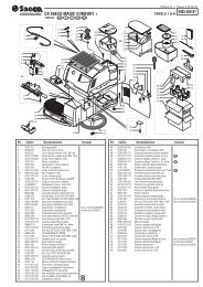
SPARE PARTS LIST ARCTIC DELUXE 12/20 LT MODEL<br />
20
1 22900-00100 20 It bowl cover 51 22900-05600 Driving shaft 12lt<br />
2 22900-00100 12 It bowl cover 51 22900-05601 Driving shaft 20lt<br />
6 22800-17200 Bowl gasket 52 22900-05400 Stirrer 12lt<br />
7 22900-00700 Plastic I-beam for connection 52 22900-05401 Stirrer 20lt<br />
8 22900-00600 Central pivot 53 22900-05500 Central shaft 12lt<br />
9 22040-00000 Central pivot OR 53 22900-05501 Central shaft 20lt<br />
10 33800-00803 Motor magnet 54 10028-01801 tube for central shaft<br />
11 22800-04800 Motor bracket 55 10533-01303 brass nut<br />
12 22800-04706 Motor 56 22900-05700 Central shaft OR.<br />
13 Back panel 57 22900-02504 Pump motor bracket<br />
14 22900-04800 20 l bowl for pump 58 33800-06701 Mixer motor<br />
15 22900-00201 Spray tube for 12 l bowl 59 22900-06200 Top cover upper part<br />
16 22900-00000 12 l bowl for pump 60 10028-04201 Plate holder for<br />
17 33900-01204 Impeller 60Hz 61 10028-04200 Bulb socket<br />
18 22800-02600 Faucet spring 62 10028-03800 28V bulb<br />
19 22900-00200 Bent tube for 20 l bowl 63 22800-11701 Top cover light contact<br />
20 22800-21900 Faucet piston 64 22900-06020 Bottom hat mechanical agitation with light<br />
21 10028-02500 Faucet gasket 64 22900-06030 Bottom hat mechanical agitation without light<br />
22 22900-04820 20 l bowl for stirrer 64 22900-06050 Bottom hat with light insulated<br />
23 21703-00000 Pinch tube 64 22900-06051 Bottom hat without light insulated<br />
24 33900-01202 Stirrer 64 22900-06000 Bottom hat without light not insulated<br />
25 22900-00020 12 l bowl for stirrer 65 22900-06400 Picture<br />
26 10029-00000 Picture 68 33900-02100 Cover complete with light insulated<br />
27 22900-00500 Push handle 68 33900-02200 Cover complete without light insulated<br />
28 22900-00800 Faucet cover 68 33900-02300 Cover complete without light not insulated<br />
29 22900-00501 Push handle 68 33900-01800 Cover with light to complete mechanical shaker<br />
30 21125-00000 Switch 68 33900-01900 Cover complete without light for mechanical shaker<br />
31 22800-05100 Switch cap<br />
32 22800-00300 Side panel Please order what printed on piece<br />
33 22800-12700 Terminal block cover See table<br />
34 22800-05500 Terminal block with cable clamp<br />
35 Overload protector<br />
36 Relay<br />
37 21907-00000 Fan for 12 lt.<br />
37A 22800-13200 Fan for 20 lt.<br />
38 22800-04706 Fan motor for 12 lt.<br />
38A 22800-04709 Fan motor for 20 lt.<br />
38B 33800-06901 Fan motor for 1 bowl<br />
39 10554-45001 Clip<br />
40 22800-10000 Rubber leg<br />
41 Dispensing side panel<br />
42 10502-55010 Stainless steel fixing screw for panel<br />
43 22900-03700 Drip tray cover<br />
44 22900-03800 Drip tray<br />
45 21087-00000 Thermostat<br />
46 22900-02502 Central pivot<br />
47 22900-02503 Washer<br />
48 33900-01011 Impeller mixer motor<br />
49 22900-03501 Mixer motor<br />
50 22900-02504 Pump motor bracket<br />
<br />
1/.. 2/.. 3/.. 4/..<br />
13 22800-06800 22900-02310 22900-02320 22900-02330<br />
41 22800-21600 22800-21700 22800-21800 22900-04100<br />
21
ARCTIC COMPACT & DELUXE<br />
WIRING DIAGRAM ARCTIC DELUXE 12/20 LT MODEL<br />
1-2 Switch<br />
3-4-5-6 Thermostat<br />
7-8-9-10 Pump/mixer switch<br />
11-12-13-14 Pump/mixer<br />
15-16 Fan Motor<br />
17-18 Compressor<br />
19-20 Transformer<br />
21-22-23-24 Top light<br />
22
NOTES:<br />
23
ARCTIC COMPACT & DELUXE<br />
NOTES:<br />
24
NOTES:<br />
25
ARCTIC COMPACT & DELUXE<br />
1 GENERAL TROUBLESHOOTING GUIDE<br />
PROBLEM CAUSE REMEDY<br />
No working at all. Neither pump motors,<br />
fan motor nor compressor run<br />
Improper or faulty electrical connection<br />
Defective main switch<br />
Locate and correct the problem<br />
Replace main switch<br />
No refrigeration at all. Pump motors and<br />
fan motor run but compressor does not<br />
run<br />
Defective overload protector or relay of<br />
compressor<br />
Replace overload protector<br />
Compressor cycles on overload protector Check the power line for low voltage and<br />
then check starting relay and overload<br />
protector and if necessary replace them<br />
Defective thermostat (always open)<br />
Replace thermostat<br />
No or poor refrigeration Not enough air flow for ventilation Provide at least 15 cm (6") of free air<br />
space all around the unit<br />
Excessive refrigeration. Compressor<br />
never stops.<br />
Condenser clogged with dust<br />
Defective fan motor<br />
Poor refrigerant gas charge<br />
Wrong temperature adjustment<br />
Clean the condenser using compressed<br />
air, vacuum or a soft brush. Condenser<br />
fins are very sharp, use extreme caution<br />
Check for possible obstacles to fan blade<br />
rotation. If necessary replace fan motor<br />
Detect possible leak, seal it and make<br />
new refrigerant charge<br />
Adjust temperature setting<br />
One defective thermostat (always closed) Replace thermostat<br />
No pumping or agitation, pump motor<br />
runs<br />
One thermostat temperature probe out<br />
from its housing<br />
Pump impeller does not spin at all<br />
Insert thermostats temperature probes<br />
properly into their housings<br />
Clean both impeller and pivot from traces<br />
of product and if necessary lubricate them<br />
with food grade grease.<br />
Pump impeller does not spin freely on<br />
pivot<br />
Check for worn impeller and if necessary<br />
replace it.<br />
No pumping or agitation, pump motor<br />
doesn't run<br />
Leak from bowls<br />
Magnetic lock decoupling (chattering)<br />
Improper or faulty electrical connection<br />
Defective pump switch<br />
Defective pump motor<br />
Drive magnet binds on evaporator<br />
assebly<br />
Broken transmission belt (Arctic Compact<br />
series with multiple bowls only)<br />
Bowl fastening hook not properly<br />
engaged<br />
Bowl gasket wrongly fitted<br />
Nicked or wrong bowl gasket<br />
Verify planarity of pump motor bracket<br />
Locate ad correct the problem<br />
Replace pump switch<br />
Replace pump motor<br />
Verify planarity of pump motor bracket<br />
Replace transmission belt<br />
Engage bowl fastening hooks<br />
Fit bowl gasket properly around its seat<br />
Replace bowl gasket<br />
Dripping from faucets (pinch tube faucet) Damaged or worn pinch tube. Replace pinch tube<br />
Faucet handle out of closing position<br />
Check faucet handle and/or its spring,<br />
replacing whichever damaged<br />
26
PROBLEM CAUSE REMEDY<br />
Dripping from faucets (gravity stainless<br />
steel faucet)<br />
Nicked or wrong stainless steel gravity<br />
piston gasket<br />
Faucet piston out of closing position<br />
Bowls faucet rim damaged<br />
Replace stainless steel piston gasket<br />
Check for stainless steel piston free<br />
movement. If necessary clean both piston<br />
and bowl housing.<br />
Check for faucet handle free movement, if<br />
necessary replace faucet handle<br />
Replace bowl<br />
Noisy unit Worn impellers Replace impellers<br />
Bent fan blade<br />
Noisy fan or pump motor<br />
Magnetic lock decoupling (chattering)<br />
Noisy ball bearings (Arctic Compact<br />
series with multiple bowls only)<br />
Re-bent fan blade to correct aligment<br />
Replace noisy motor<br />
Verify planarity of pump motor bracket<br />
Replace magnetic pulley assembly<br />
No magnetic slow mixer rotation Defective drive motor Replace drive motor<br />
Magnetic mixer does not rotate freely on<br />
pivot<br />
Ice on the evaporator<br />
Clean both mixer and pivot from traces of<br />
product and if necessary lubricate them<br />
with food grade grease<br />
Increase product level into the bowl<br />
Adjust temperature setting<br />
Check thermostats<br />
No mechanic slow mixer rotation Defective drive motor Replace drive motor<br />
Product excessive thicknes<br />
27
<strong>Ugolini</strong> spa<br />
Via dei Pioppi, 33 - 20090 Opera - (MI)<br />
Tel. 02.530059.1 - Fax. 02.530059260<br />
www.ugolinispa.com<br />
E-Mail: sales@ugolinispa.com<br />
2428_02 V0.2 09C09