Operators G & MG & ID Series Granita
Operators G & MG & ID Series Granita
Operators G & MG & ID Series Granita

You also want an ePaper? Increase the reach of your titles
YUMPU automatically turns print PDFs into web optimized ePapers that Google loves.
1<br />
2<br />
3<br />
4<br />
5<br />
6<br />
7<br />
8<br />
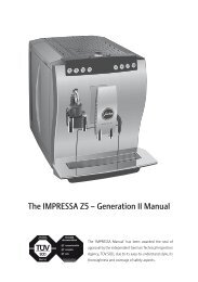
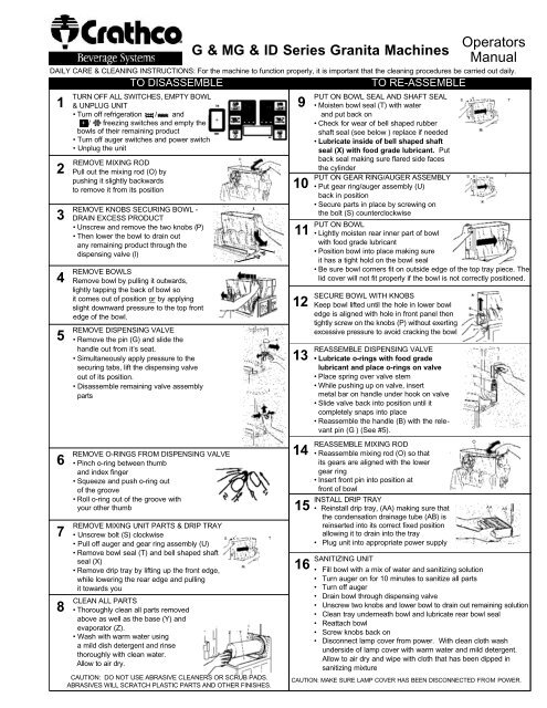
TURN OFF ALL SWITCHES, EMPTY BOWL<br />
& UNPLUG UNIT<br />
• Turn off refrigeration / and<br />
/ freezing switches and empty the<br />
bowls of their remaining product<br />
• Turn off auger switches and power switch<br />
• Unplug the unit<br />
REMOVE MIXING ROD<br />
Pull out the mixing rod (O) by<br />
pushing it slightly backwards<br />
to remove it from its position<br />
TO DISASSEMBLE<br />
REMOVE KNOBS SECURING BOWL -<br />
DRAIN EXCESS PRODUCT<br />
• Unscrew and remove the two knobs (P)<br />
• Then lower the bowl to drain out<br />
any remaining product through the<br />
dispensing valve (l)<br />
REMOVE BOWLS<br />
Remove bowl by pulling it outwards,<br />
lightly tapping the back of bowl so<br />
it comes out of position or by applying<br />
slight downward pressure to the top front<br />
edge of the bowl.<br />
REMOVE DISPENSING VALVE<br />
• Remove the pin (G) and slide the<br />
handle out from it’s seat.<br />
• Simultaneously apply pressure to the<br />
securing tabs, lift the dispensing valve<br />
out of its position.<br />
• Disassemble remaining valve assembly<br />
parts<br />
REMOVE O-RINGS FROM DISPENSING VALVE<br />
• Pinch o-ring between thumb<br />
and index finger<br />
• Squeeze and push o-ring out<br />
of the groove<br />
• Roll o-ring out of the groove with<br />
your other thumb<br />
REMOVE MIXING UNIT PARTS & DRIP TRAY<br />
• Unscrew bolt (S) clockwise<br />
• Pull off auger and gear ring assembly (U)<br />
• Remove bowl seal (T) and bell shaped shaft<br />
seal (X)<br />
• Remove drip tray by lifting up the front edge,<br />
while lowering the rear edge and pulling<br />
it towards you<br />
CLEAN ALL PARTS<br />
• Thoroughly clean all parts removed<br />
above as well as the base (Y) and<br />
evaporator (Z).<br />
• Wash with warm water using<br />
a mild dish detergent and rinse<br />
thoroughly with clean water.<br />
Allow to air dry.<br />
CAUTION: DO NOT USE ABRASIVE CLEANERS OR SCRUB PADS.<br />
ABRASIVES WILL SCRATCH PLASTIC PARTS AND OTHER FINISHES.<br />
G & <strong>MG</strong> & <strong>ID</strong> <strong>Series</strong> <strong>Granita</strong> Machines<br />
9<br />
10<br />
11<br />
12<br />
13<br />
14<br />
15<br />
16<br />
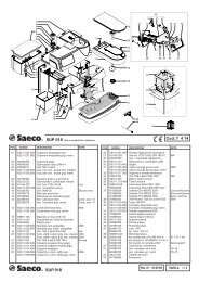
PUT ON BOWL SEAL AND SHAFT SEAL<br />
• Moisten bowl seal (T) with water<br />
and put back on<br />
• Check for wear of bell shaped rubber<br />
shaft seal (see below ) replace if needed<br />
• Lubricate inside of bell shaped shaft<br />
seal (X) with food grade lubricant. Put<br />
back seal making sure flared side faces<br />
the cylinder<br />
PUT ON GEAR RING/AUGER ASSEMBLY<br />
• Put gear ring/auger assembly (U)<br />
back in position<br />
• Secure parts in place by screwing on<br />
the bolt (S) counterclockwise<br />
PUT ON BOWL<br />
• Lightly moisten rear inner part of bowl<br />
with food grade lubricant<br />
• Position bowl into place making sure<br />
it has a tight hold on the bowl seal<br />
•<br />
• Be sure bowl corners fit on outside edge of the top tray piece. The<br />
lid cover will not fit properly if the bowl is not correctly positioned.<br />
SECURE BOWL WITH KNOBS<br />
Keep bowl lifted until the hole in lower bowl<br />
edge is aligned with hole in front panel then<br />
tightly screw on the knobs (P) without exerting<br />
excessive pressure to avoid cracking the bowl<br />
REASSEMBLE DISPENSING VALVE<br />
• Lubricate o-rings with food grade<br />
lubricant and place o-rings on valve<br />
• Place spring over valve stem<br />
• While pushing up on valve, insert<br />
metal bar on handle under hook on valve<br />
• Slide valve back into position until it<br />
completely snaps into place<br />
• Reassemble the handle (B) with the relevant<br />
pin (G ) (See #5).<br />
REASSEMBLE MIXING ROD<br />
• Reassemble mixing rod (O) so that<br />
its gears are aligned with the lower<br />
gear ring<br />
• Insert front pin into position at<br />
front of bowl<br />
INSTALL DRIP TRAY<br />
• Reinstall drip tray, (AA) making sure that<br />
the condensation drainage tube (AB) is<br />
reinserted into its correct fixed position<br />
allowing it to drain into the tray<br />
• Plug unit into appropriate power supply<br />
SANITIZING UNIT<br />
TO RE-ASSEMBLE<br />
<strong>Operators</strong><br />
Manual<br />
DAILY CARE & CLEANING INSTRUCTIONS: For the machine to function properly, it is important that the cleaning procedures be carried out daily.<br />
P<br />
O<br />
S X U T<br />
I<br />
S X U T<br />
S X U T<br />
• Fill bowl with a mix of water and sanitizing solution<br />
• Turn auger on for 10 minutes to sanitize all parts<br />
• Turn off auger<br />
• Drain bowl through dispensing valve<br />
• Unscrew two knobs and lower bowl to drain out remaining solution<br />
• Clean tray underneath bowl and lubricate rear bowl seal<br />
• Reattach bowl<br />
• Screw knobs back on<br />
• Disconnect lamp cover from power. With clean cloth wash<br />
underside of lamp cover with warm water and mild detergent.<br />
Allow to air dry and wipe with cloth that has been dipped in<br />
sanitizing mixture<br />
CAUTION: MAKE SURE LAMP COVER HAS BEEN DISCONNECTED FROM POWER.<br />
BK<br />
O<br />
O<br />
AA<br />
AB
G23-2B ELECTRONIC MODEL GU<strong>ID</strong>E:<br />
MAIN POWER SWITCH:<br />
1. Turns unit ON.<br />
2. Selects 12/24 time or FÞ/CÞ temperature display when turned ON<br />
while simultaneously depressing the auger button.<br />
3. Sets current time when turned ON while simultaneously depressing<br />
the “Mode/Press To Select Function” button.<br />
AUGER ON/OFF BUTTON:<br />
1. Turns auger ON and OFF when main power switch is ON.<br />
2. Must be ON to permit defrost time to be reset.<br />
3. Must be ON to activate the “Mode/Press To Select Function” button<br />
to select manual “OFF”, “FREEZE” or “COOLING” functions.<br />
MODE/PRESS TO SELECT FUNCTION BUTTON:<br />
1. Use to manually select “OFF”, “FREEZE” or “COOLING” functions<br />
when auger is turned ON.<br />
2, Accesses defrost timer reset mode when depressed for an extended<br />
period when auger is turned ON.<br />
3. Locks in hours, minutes and final time settings after they are reset<br />
using the “Auto Timer” button.<br />
4. Does not function when light on “Auto Timer” button is illuminated.<br />
“AUTO TIMER” BUTTON:<br />
1. Turns auto defrost mode ON or OFF (light on switch indicates when<br />
auto defrost mode is activated).<br />
2, Used to adjust the hours and minutes settings when readjusting<br />
current time or auto defrost timer.<br />
ENTER TIME PROGRAMMING ON INITIAL INSTALLATION OR IN THE<br />
EVENT OF A TIME CHANGE:<br />
1. Turn OFF power switch.<br />
2. While pressing left “Press to Select Function” button, turn ON power<br />
switch while continuing to hold the “Press To Select Function” button<br />
until the display illuminates (hour digits will start to blink).<br />
3. First set hour by pressing the “Auto Timer” clock button until the<br />
appropriate hour is shown.<br />
Note: When using a 12 hour clock the time is P.M. when the dot at the bottom<br />
right corner of the LED is lit; when dot is not lit it is A.M.)<br />
4. To set the minutes press the left “Press To Select Function” button,<br />
then press the “Auto Timer” clock button until the appropriate minutes<br />
are set.<br />
5. To save your settings press the “Press To Select Function” button<br />
one more time.<br />
G23-2B SETTING DEFROST TIMER (Night Setting):<br />
1. Turn the power switch on.<br />
2. Then press “Auger ON/OFF” button on for the side you are setting.<br />
3. Then press and hold the “Press to Select Function” button until you<br />
hear a long beep and the LED and clock light begins to blink.<br />
4. Press the “Auto Timer” clock button to set the hour you want it to turn<br />
to refrigeration mode and then press “Press to Select Function” to<br />
save the setting.<br />
5. Then press the “Auto Timer” clock to set the minutes to complete<br />
time<br />
setting that you want it to turn to refrigeration mode. Then press the<br />
“Press to Select Function” button to save the setting.<br />
6. Proceed to setting the time you want the machine to turn to freezing<br />
mode by following steps 4 and 5 above. Then press the “Press to<br />
Select Function” button to save the time settings for freeze mode.<br />
Note: Once the settings have been saved, the unit will save the settings,<br />
even when the power switch is turned off.<br />
When the light on the “Auto Timer” clock button is “on”, the defrost timer is<br />
activated. To turn off the defrost timer, press the clock buttons until the<br />
lights on the clock buttons turn off.<br />
G23-2B - TO OPERATE IN AUTOMATIC MODE (WITH DEFROST TIMER<br />
ACTIVATED)<br />
1. Turn power switch on and wait for LED to light up.<br />
2. To operate in defrost mode the light on the “Auto Timer” clock button<br />
should be illuminated.<br />
3. If it is not, press the “Auto Timer” clock button<br />
to turn on automatic mode.<br />
G23-2B OPERATE IN MANUAL MODE (WITHOUT<br />
DEFROST TIMER ACTIVAT-<br />
ED)<br />
1. Turn power switch on<br />
and wait for LED to light<br />
up.<br />
2. Make sure clock button<br />
is off (LED light on clock<br />
button should not be lit<br />
up).<br />
3. First turn auger on by<br />
pressing “Auger<br />
ON/OFF” button until it<br />
beeps. (Note: The auger<br />
-To access the operating panel, open the cover on the right side<br />
PROGRAMMING of the unit.<br />
To access the control panel, open the cover on the right side of the unit<br />
must be on before unit will allow the cooling or freezing mode to activate.)<br />
4. Then select refrigeration or freezing mode by pressing the “Press to<br />
Select Function” button until the light under the selection you desire is lit<br />
up. Note: In the cooling mode the LED will read the actual temperature of<br />
the product (The temperature setting is preset to NSF standards and is<br />
not adjustable.) In the freezing mode the LED will read the current time.<br />
ERROR MESSAGES<br />
“FILTER CLEANING” ALARM<br />
A filter cleaning alarm will activate when the unit is running hot due to insufficient<br />
internal air circulation. When this occurs a “Filtr” message will appear on<br />
the touchpad LED readout and an intermittent audible tone will also sound to<br />
alert the operator of this condition.<br />
The “Filtr” message will appear when the alarm activates (a beeping sound<br />
every 4-5 seconds). To determine the condition that caused the alarm and correct<br />
problem, see list of conditions below:<br />
• Condition: Filter is dirty and needs to be cleaned<br />
Corrective Action: Clean and replace filter following instructions.<br />
• Condition: Unit is positioned too close to a wall or other objects restricting<br />
air flow and causing the machine to run at a higher temperature.<br />
Corrective Action: Reposition unit to maximize ventilation space.<br />
• Condition: Filter is not properly installed.<br />
Corrective Action: Properly install filter.<br />
• Condition: Unit has been installed near a heat source, such as a coffee<br />
machine, ice maker or cold beverage machine which expels hot air from its<br />
vents, causing the machine to run at a high temperature. (Installation near<br />
a heat source should be avoided)<br />
Corrective Action: Reposition unit to maximize ventilation.<br />
“SYSTEM OVER TEMPERATURE” ALARM<br />
• A system over temperature alarm will activate as a safety when the unit has<br />
overheated to protect the compressor.<br />
• The system automatically goes to “OFF” status where the compressor’s operations<br />
are stopped, while augers will keep working to avoid forming ice<br />
blocks.<br />
• When this “Err” message will appear on the touch pad LED readout accompanied<br />
by a continuous buzzer sound to alert the operator of this condition.<br />
• When this alarm activates, turn off all switches. Then determine the condition<br />
from the list above.<br />
<strong>MG</strong>23-2B & <strong>ID</strong>2.2 TRADITIONAL ROCKER SWITCH MODEL<br />
GU<strong>ID</strong>E<br />
Important: The mixing parts/auger switch should be on prior<br />
to activating the freezing or refrigeration switches.<br />
(E) activates the mixing parts/spiral auger<br />
(F) activates the freezing of the product<br />
(G) activates the refrigeration of the product<br />
(D) is the main power switch<br />
FROZEN BEVERAGE - select (E) and (F)<br />
Note: There is a 4 minute delay before the compressor starts.<br />
COLD BEVERAGE - select (E) and (G)<br />
STANDBY (Night Setting) - select (E) and (G)<br />
* Defrost timers are installed in each unit and can be set to automatically<br />
place units in defrost mode and back to frozen mode. All switches must be<br />
on for defrost timer to properly function.<br />
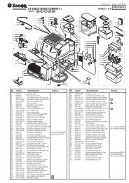
<strong>MG</strong>23-2B SETTING DEFROST TIMER (& <strong>ID</strong>2.2 When Equipped)<br />
NOTE: All switches (power, auger, refrigeration and freeze) must be “on” for<br />
defrost timer to properly function.<br />
• Setting Current Time - Rotate<br />
the program disc, in the<br />
direction of the arrows,<br />
to align the correct time of<br />
day with the time of day mark<br />
• Setting Defrost Mode -<br />
Push the switch activator toward<br />
the outer edge of the<br />
program disc. Freeze time<br />
is set by pushing the switch actuators toward the center of the time switch.<br />
The light and dark shaded areas of the program disc indicate day and<br />
night. Each actuator is equivalent to 15 minutes<br />
• The drawing shows a defrost time from 11:00 to 6:15<br />
THE TIMER IS BATTERY BACKED TO PROTECT SETTINGS DURING<br />
POWER FAILURE. THE BATTERY BACK-UP FEATURE WILL FAIL IF<br />
POWER IS REMOVED FROM THE UNIT FOR MORE THAN 2 WEEKS
c<br />
d<br />
a<br />
b<br />
g<br />
h<br />
e<br />
f<br />
m<br />
n<br />
i<br />
j<br />
k<br />
l<br />
o<br />
p<br />
q<br />
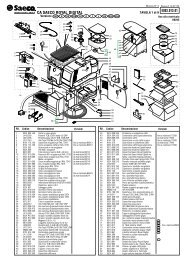
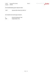
ITEM DESCRIPTION<br />
PART NUMBER<br />
a) Drip Tray - Black 90409<br />
Drip Tray - White 90026<br />
b) Drip Tray Grid - Black 90408<br />
Drip Tray Grid - White 90025<br />
c) Incandescent Light Bulb 90142<br />
d) Knob to secure Bowl - Black 90426<br />
Knob to secure Bowl - White 90024<br />
e) Upper Mixing Bar 90065<br />
f) Seal for Bowl 90023<br />
g) Dispensing Valve Handle - Black 90401<br />
Dispensing Valve Handle - White 90041<br />
h) Handle Securing Pin - Black 90402<br />
Handle Securing Pin - White 90042<br />
Key Replacement Parts<br />
ITEM DESCRIPTION<br />
i) Auger 90444<br />
j) Spindle Bushing 90069<br />
k) Shaft Seal, Rubber Bell Shaped - Black 90066<br />
l) Securing Nut for Auger 90068<br />
m)Dispensing Valve Spring 90044<br />
n) Dispensing Valve Upper Body 90043<br />
o) Food Grade Lubricant 90112<br />
p) Dispensing Valve Lower Body - 90403<br />
G & GM <strong>Series</strong><br />
Dispensing Valve Lower Body - 90045<br />
<strong>ID</strong> <strong>Series</strong><br />
q) Dispensing Valve O-ring 90046<br />
IMPORTANT-PREVENTATIVE MAINTENANCE<br />
PART NUMBER<br />
The following Preventative Maintenance Items should be performed per the recommended schedule in order to maximize the life of your machine and to insure<br />
warranty coverage. (For a checklist of all P.M. items, contact GCS or check the website.)<br />
1. Lubricate bell shaped shaft seal and dispense valve o-rings following daily cleaning procedure.<br />
2. Check bell shaped shaft seal for wear and replace when needed (every 1-6 months or more often if necessary). Seal is worn if edges that touch barrel<br />
curl back.<br />
3. Clean air filter weekly and condenser monthly or more often if necessary.<br />
4. Check dispense valve o-rings for wear and replace as needed (every 3-6 months during complete PM or more often if necessary).<br />
5. Perform complete PM every 3-6 months.<br />
!<br />
WARNING Disconnect the unit from its power supply prior to performing<br />
any maintenance procedures. Failure to do so could result in electric<br />
shock from hazardous parts or serious burns from hot surfaces.<br />
REMOVING AND CLEANING THE FILTER IF EQUIPPED<br />
(G & <strong>MG</strong> MODELS STANDARD; <strong>ID</strong> MODELS OPTIONAL)<br />
In order to guarantee an efficient refrigerating system, it is<br />
essential that the filter be properly cleaned, according to the<br />
following procedures:<br />
!<br />
Attention: Failure to maintain a clean filter and condenser<br />
will cause damage to the unit not covered by warranty.<br />
• Unscrew the knob (K) on rear panel in order to have the<br />
full back panel in your hands - (G, <strong>MG</strong>) on <strong>ID</strong> pull filter<br />
cover from unit at bottom of cover, pull down to remove.<br />
• Remove the filter (W) held inside the back panel (X) and<br />
clean it properly using water or vacuum. Allow to dry.<br />
• Put the clean dry filter back to its position and reinstall the back panel on<br />
machine by screwing in the knob (K) or reattaching filter cover.<br />
CLEANING CONDENSER<br />
• Remove the back panel<br />
• Using a dry brush or vacuum, remove the dust<br />
that has accumulated between the fins of the<br />
condenser<br />
CHANGING LIGHT BULB<br />
• To access the lightbulb insert the tip of a coin or<br />
small screwdriver in the slot on the cover and<br />
rotate to pop the panel open<br />
• Holding the cover, carefully remove the lightbulb.<br />
• Insert the new bulb and replace the light cover<br />
REAR MERCHANDISER LIGHTS<br />
• In order to access the lightbulb from the rear back<br />
lit merchandiser, remove the rear merchandiser by<br />
sliding it upwards.<br />
• Then remove the lightbulb(s). Insert the new bulb(s).<br />
• Reassemble the rear back-lit merchandiser making sure that its slots are<br />
inserted properly in the relevant brackets.
INSTALLATION<br />
CONSISTENCY ADJUSTMENTS<br />
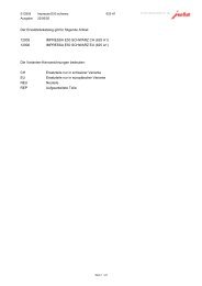
POSITIONING THE MACHINE<br />
The machine must be well ventilated, with an 8” (20 cm) clearance<br />
on the sides and back of the machine. Do not install<br />
near a heat source such as ovens, coffee machines, cold or<br />
frozen beverage dispensers or ice machines (equipment with<br />
compressors that expel hot air through its vents). Do not position<br />
near dust producing units such as a Powdered<br />
Cappuccino or Cocoa dispenser. A room temperature<br />
between 59ÞF (15ÞC) and 77ÞF (25ÞC) is recommended<br />
REMOVE SHIPPING PIN<br />
!<br />
Attention: Shipping pin attached to tag located behind each bow must<br />
be removed before starting machines.<br />
INSTALLING THE TOP L<strong>ID</strong> MERCHANDISER<br />
(requires Phillips head screwdriver)<br />
1. Remove hole plugs and screws.<br />
2. Remove or replace graphic by sliding<br />
it around the outside edge of the lid’s<br />
clear plastic base. Position bottom edge of<br />
header in grooved area.Reassemble the<br />
top cover onto the clear plastic base. The<br />
top edge of header should slide into top<br />
cover grooved area.<br />
INSTALLING REAR GRAPHIC<br />
1. Pinch or bend graphic and pull it out to<br />
remove.<br />
TROUBLESHOOTING GU<strong>ID</strong>E<br />
Problem Possible Cause Solution<br />
The machine over-freezes, making the auger<br />
movement slow or stopped<br />
Product is leaking out of the bowl<br />
The machine does not cool, or cools only<br />
partially, but the compressors are running<br />
The cover does not fit properly on the bowl<br />
Product is leaking from the dispensing valve<br />
Product is flowing into drain tray through<br />
drainage tube<br />
The auger and/or the upper mixing unit is<br />
not turning<br />
• The product brix is too low<br />
• The screw setting for the product consistency control system is<br />
set too far toward the “+” position<br />
• The level of the product in the bowl is too low, exposing the<br />
auger<br />
• One of the bowl seals is not in place<br />
• Freezer is in defrost mode<br />
• The space around the machine is inadequate for ventilation<br />
• The condenser fins are clogged with airborne particles<br />
• The bowl is incorrectly positioned. The lower right and/or left<br />
corner edge of bowl is not over the lower triangle edge<br />
• The dispening valve has been incompletely or incorrectly<br />
replaced in its position<br />
• The free movement of the dispensing valve is impeded<br />
• Dispensing valve o-rings are damaged<br />
• The bell shaped “shaft” seal between the front of the cylinder<br />
and the auger hub has not been reinstalled properly<br />
• Auger not turned on<br />
8"<br />
(20 cm)<br />
CONNECTION TO MAIN POWER SUPPLY<br />
Install in properly grounded, electrical receptacle that is in compliance with current<br />
national safety standards. Grindmaster Crathco Systems, Inc. is not responsible for<br />
damage and/or injury caused by failure to follow above precautions.<br />
• Only connect to a dedicated outlet.<br />
• Altering the cord or plug will void the warranty.<br />
• Do not compress, bend or bunch power cord or use extension cord.<br />
CONSISTENCY ADJUSTMENTS<br />
• Unplug the machine<br />
• Product in bowl should be within proper fill range<br />
• Change the thickness of product<br />
by turning the screw (M) on the<br />
back of bowl clockwise for thinner<br />
product or counterclockwise for<br />
thicker product<br />
• The indicator gauge (N), located on the<br />
back of the bowl, shows the degree of<br />
adjustment (+/-) (+) = thicker, (-) = thinner<br />
TOO THICK OF A PRODUCT CAN BE PREVENTED BY SWITCHING THE<br />
FREEZING MODE (F) "OFF" OR BY REFILLING THE BOWL WHEN<br />
PRODUCT IS BELOW MINIMUM FILL LINE<br />
PRODUCT HINTS<br />
• To maintain product quality place unit in standby (refrigeration) mode at<br />
night to allow product to thaw out, and then refreeze the next day. This<br />
will promote smoother product and smaller ice crystal growth. (Defrost<br />
timer can be programmed to do this for you automatically at preset<br />
times.)<br />
HELPFUL HINTS<br />
PREPARING PRODUCT<br />
• Make sure that your product has a 13% minimum<br />
sugar content (BRIX). A lower concentrate could<br />
damage the mixing parts and gear motors.<br />
NEVER USE ONLY WATER.<br />
• Premix all product in a separate container.<br />
NEVER pour dry powder, crystals or concentrate<br />
into a dry bowl.<br />
• There is no need to remove lid for refilling.<br />
Simply slide lid back until “stops” are reached.<br />
• Note and follow minimum and maximum fill<br />
lines on bowl. Do not overfill, or run the unit<br />
without enough product.<br />
• Check the product brix and correct<br />
• Reset the screw toward the “-” position to<br />
produce a thinner consistency product<br />
• Add more product or turn the refrigeration “Off”<br />
• Replace or reposition the seals<br />
• Return to freeze mode<br />
• Allow at least 8" between the machine and<br />
anything next to it; keep away from heat sources<br />
• Remove the side panels and using a brush or<br />
compressed air to clean the condenser<br />
• Remove bowl and position properly<br />
• Reassemble and replace<br />
• Clean and lubricate the valve and valve cylinder with<br />
the lubricant provided with the machine<br />
• Replace the o-rings<br />
• Find the seal and put it back in place<br />
• Turn auger on<br />
If you still need help, call our service department at (800) 695-4500 (Monday through Friday, 8 am - 6 pm EST) or an authorized service center in your<br />
area. Please have the model and serial numbers ready so that accurate information may be given.<br />
Prior authorization must be obtained from Grindmaster Crathco Systems’ Technical Services Department for all warranty claims.<br />
Grindmaster Crathco Systems, Inc. 1999<br />
PRINTED IN USA<br />
0101 Form # CC-904-04<br />
Part # 90386