WhirlWind Combined fully integrated gas/air control and safety ...
WhirlWind Combined fully integrated gas/air control and safety ...
WhirlWind Combined fully integrated gas/air control and safety ...

You also want an ePaper? Increase the reach of your titles
YUMPU automatically turns print PDFs into web optimized ePapers that Google loves.
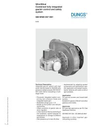
<strong>WhirlWind</strong><br />
<strong>Combined</strong> <strong>fully</strong> <strong>integrated</strong><br />
<strong>gas</strong>/<strong>air</strong> <strong>control</strong> <strong>and</strong> <strong>safety</strong><br />
system<br />
GB-WND 055 D01<br />
3.04<br />
Printed in Germany • Rösler Druck • Edition 02.08 • Nr. 240 508<br />
1 … 6<br />
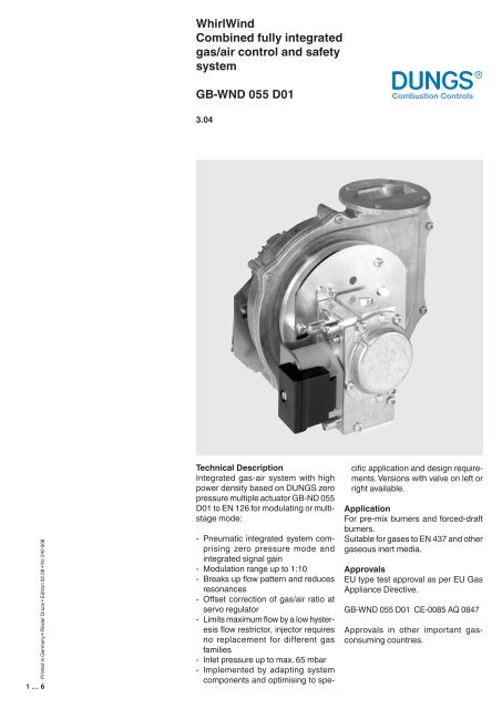
Technical Description<br />
Integrated <strong>gas</strong>-<strong>air</strong> system with high<br />
power density based on DUNGS zero<br />
pressure multiple actuator GB-ND 055<br />
D01 to EN 126 for modulating or multistage<br />
mode:<br />
- Pneumatic <strong>integrated</strong> system comprising<br />
zero pressure mode <strong>and</strong><br />
<strong>integrated</strong> signal gain<br />
- Modulation range up to 1:10<br />
- Breaks up flow pattern <strong>and</strong> reduces<br />
resonances<br />
- Offset correction of <strong>gas</strong>/<strong>air</strong> ratio at<br />
servo regulator<br />
- Limits maximum flow by a low hysteresis<br />
flow restrictor, injector requires<br />
no replacement for different <strong>gas</strong><br />
families<br />
- Inlet pressure up to max. 65 mbar<br />
- Implemented by adapting system<br />
components <strong>and</strong> optimising to spe-<br />
cific application <strong>and</strong> design requirements.<br />
Versions with valve on left or<br />
right available.<br />
Application<br />
For pre-mix burners <strong>and</strong> forced-draft<br />
burners.<br />
Suitable for <strong>gas</strong>es to EN 437 <strong>and</strong> other<br />
<strong>gas</strong>eous inert media.<br />
Approvals<br />
EU type test approval as per EU Gas<br />
Appliance Directive.<br />
GB-WND 055 D01 CE-0085 AQ 0847<br />
Approvals in other important <strong>gas</strong>consuming<br />
countries.
Combinations<br />
Multifunctional <strong>gas</strong> <strong>control</strong> valve GB-WND 055 D01<br />
Main types<br />
Specification<br />
Zero pressure<br />
servo regulator<br />
Operating valve<br />
Solenoid valve<br />
[class]<br />
Safety valve<br />
Solenoid valve<br />
[class]<br />
Maximum<br />
restrictor<br />
Offset correction<br />
Baffle to signal<br />
amplifier<br />
Blower adapter<br />
Dirt trap<br />
device<br />
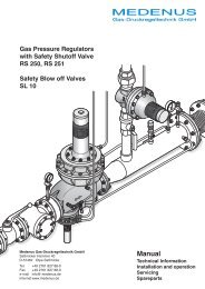
Gas pressure<br />
switch<br />
Line socket<br />
MPA 109x<br />
GB-WND 055 D01<br />
B<br />
B<br />
st<strong>and</strong>ard optional not available<br />
Type key of Gasbloc<br />
GB- XXXXX XXX DXX SXX<br />
Control of V1 <strong>and</strong> V2<br />
0 = common<br />
2 = separated<br />
Outlet pressure Inlet pressure<br />
0 = 0 mbar bis 65 mbar<br />
2 = 1,5 - 20 mbar bis 65 mbar<br />
4 = 3 - 40 mbar bis 65 mbar<br />
S = Series (type-independent)<br />
Gas train schematic diagram<br />
1 = two class B solenoid valves with pressure regulator<br />
2 = two class B solenoid valves without pressure regulator<br />
Valve design<br />
0 = Double valve<br />
1 = Single valve, right angle<br />
2 = Single valve, straight<br />
Design type (generation) D<br />
Construction size, nominal diameter<br />
05 = p max. = 65 mbar<br />
3 = Rp 1/4<br />
5 = Rp 1/2<br />
7 = Rp 3/4<br />
Opening behaviour + main volume restrictor<br />
without = fast-opening, fast-closing<br />
-L = slow-opening<br />
-E = adjustable start <strong>gas</strong><br />
-P = pilot<strong>gas</strong> connection<br />
-G = Gas/Air ratio<br />
-D = main flow setting<br />
-N = Zero-Governor<br />
-M = electrical modulating type<br />
-W = Whirlwind version<br />
-Z = two stage<br />
GasBloc<br />
Air/differential pressure switch<br />
(Optional equipment)<br />
The system offers the option of connecting<br />
an <strong>air</strong> or differential pressure<br />
switch for monitoring blower function.<br />
The <strong>air</strong> or differential pressure switch<br />
can be pre-adjusted <strong>and</strong> sealed to<br />
customer specifications.<br />
Pressure instrument gl<strong>and</strong>s<br />
On inlet <strong>and</strong> outlet sides<br />
Solenoid valve modes<br />
V1 <strong>and</strong> V2 can be activated <strong>and</strong> opened<br />
either together or separately.<br />
Description of main components<br />
Valve <strong>and</strong> pressure regulator<br />
Optionally, the valve can be supplied<br />
with a side outlet on the left or right.<br />
The <strong>WhirlWind</strong> system is therefore<br />
adaptable to the design requirements<br />
of an application. The pressure <strong>control</strong><br />
unit <strong>and</strong> servo pressure regulator<br />
compensates for pressure fluctuations<br />
in the supply network. This ensures<br />
a constant volume flow at constant<br />
injector pressure. The servo regulator<br />
regulates the nozzle pressure at the<br />
valve outlet, dependent on the vacuum<br />
generated, towards zero.<br />
Solenoid valves<br />
Solenoid valve to EN 161, Class B. DC coil,<br />
protected against voltage transients.<br />
Swirl plate<br />
The <strong>integrated</strong> baffle acts as a twostage<br />
cascaded signal amplifier <strong>and</strong><br />
permits safe operation over a modulation<br />
range up to 1:10. The specially designed,<br />
patented. Swirl plate changes<br />
flow patterns to reduce resonances.<br />
Blower adapter<br />
Represents the interface to the selected<br />
blower <strong>and</strong> ensure defined flow<br />
ratios at the inlet <strong>and</strong> design flexibility<br />
in the valve/blower arrangement.<br />
Gas pressure switch<br />
Optional equipment<br />
Monitors <strong>gas</strong> pressure on the inlet side<br />
for <strong>gas</strong> leakage protection. The pressure<br />
switch can be pre-adjusted <strong>and</strong><br />
sealed to customer specifications.<br />
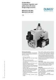
Block diagram<br />
A Filter<br />
B Automatic shut-off valves<br />
C Pressure regulator<br />
D Servo-pressure regulator<br />
E Main flow restrictor<br />
F Nozzle<br />
G Baffle for signal gain<br />
H Fan<br />
p 1<br />
Test nipple, inlet<br />
p 2<br />
Test nipple, outlet<br />
A<br />
P1<br />
B B D<br />
C<br />
V1<br />
V2<br />
P amb<br />
P2 E<br />
F<br />
G<br />
H<br />
Filter<br />
Fine-meshed strainer to protect fitting.<br />
Side cover plate with nozzle<br />
Cover plate mounted on the side between<br />
valve <strong>and</strong> baffle to guide supply<br />
<strong>air</strong> <strong>and</strong> act as noise insulation. The nozzle<br />
is mounted between the valve <strong>and</strong><br />
the cover plate <strong>and</strong> can be replaced in<br />
the event of changes in <strong>gas</strong> families.<br />
2 … 6
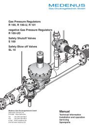
Functional diagram GB-WND 055 D01<br />
p 2<br />
15<br />
14<br />
7<br />
5<br />
6<br />
4<br />
9<br />
10<br />
16<br />
17<br />
p 2<br />
3<br />
11<br />
V1 V2<br />
13<br />
2<br />
12<br />
1<br />
p 1<br />
8<br />
18<br />
19<br />
Legend<br />
1 Fine-meshed strainer<br />
2 Housing<br />
3 Valve V1<br />
4 Closing spring<br />
5 Plunger V1<br />
6 Test nipple<br />
7 Solenoid V1<br />
8 Valve V2<br />
9 Start <strong>gas</strong> setting<br />
10 Solenoid V2<br />
11 Working diaphragm<br />
12 Return spring<br />
13 Operating valve<br />
14 Electrical connection<br />
15 Servo-pressure regulator<br />
16 Injector<br />
17 Swirl plate<br />
18 Blower adapter<br />
19 Side cover plate<br />
Setting the CO 2<br />
characteristic<br />
GB-WND 055 D01<br />
CO 2<br />
[%]<br />
10<br />
9<br />
8<br />
Emission<br />
7<br />
6<br />
5<br />
Setting by means of<br />
offset adjustment<br />
Setting by means of<br />
maximum restrictor<br />
4<br />
3<br />
2<br />
1<br />
Adjustment instructions<br />
0<br />
0 10 20 30 40 50 60 70 80<br />
Rating<br />
90 100<br />
Q [%]<br />
Rapid <strong>and</strong> simple adjustment by<br />
means of:<br />
• Adjust offset correction using setting<br />
screw on servo regulator.<br />
• Adjust maximum flow using flowrestriction<br />
screw.<br />
3 … 6
Dimensions [mm]<br />
150,5<br />
58<br />
ø 9<br />
4 x M4 - 7 deep<br />
Rp 1/2 ISO 7/1<br />
R 63<br />
2<br />
R 50<br />
3 x ø 4,5<br />
82<br />
60<br />
12,5<br />
76<br />
34<br />
102<br />
128,5<br />
30 ϒ<br />
24<br />
34<br />
105<br />
18,9<br />
8,4<br />
Adjusting devices<br />
Electrical connection<br />
Maximum restrictor<br />
Pressure test<br />
nipple P 2<br />
Pressure<br />
regulator offset<br />
adjustment<br />
Pressure<br />
test nipple<br />
P 1<br />
Solenoid coils<br />
St<strong>and</strong>ard<br />
Box with cable connection IP 40<br />
Molex Crimp System 3001<br />
4 … 6
Swirl Plate GB-WND 055 D01<br />
Integrated venturi<br />
2. Signal amplifier<br />
Spiral baffle plates<br />
1. Signal amplifier<br />
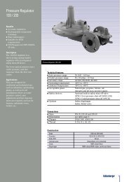
Volume flow pressure difference characteristic<br />
GB-WND 055 D01 - pneumatic to DIN EN 126<br />
100<br />
80<br />
60<br />
50<br />
40<br />
recommended work range<br />
30<br />
∆p [mbar]<br />
20<br />
10<br />
8<br />
6<br />
5<br />
4<br />
3<br />
2<br />
Based on + 15° C, 1013 mbar, dry<br />
1<br />
0,1 0,2 0,3 0,4 0,5 0,6 0,8 1 2 3 4 5 6 7 8 910 20<br />
Vn ° 3<br />
[m /h] Luft / Air / Aria dv = 1,00<br />
Permissible deviation<br />
Pressure regulator class C<br />
0,2 0,3 0,4 0,50,6 0,8 1 2 3 4 5 6 7 8 910 20 30<br />
Vn °<br />
3<br />
[m /h] Erd<strong>gas</strong>/Natural <strong>gas</strong>/Gaz Naturel/Gas metano dv = 0,65<br />
p 2<br />
±10 % as per EN 126<br />
5 … 6
<strong>WhirlWind</strong><br />
<strong>Combined</strong> <strong>fully</strong> <strong>integrated</strong><br />
<strong>gas</strong>/<strong>air</strong> <strong>control</strong> <strong>and</strong> <strong>safety</strong> system<br />
GB-WND 055 D01<br />
Specifications Nominal diameter<br />
DN 15<br />
Gas connection<br />
Rp 1/2<br />
G 3/4<br />
ISO 7/1<br />
DIN ISO 228 OD<br />
Flange with tube thread<br />
Rp 1/2<br />
G 3/4<br />
ISO 7/1 ID<br />
DIN ISO 228 OD<br />
Max. inlet pressure<br />
Nominal flow<br />
Ambient temperature<br />
Automatic shut-off valves<br />
Group<br />
Pressure regulator<br />
Proportional adjustment range V<br />
Minimum signal pressure<br />
Offset correction<br />
Degree of protection<br />
Opening time<br />
Closing time<br />
Switch on duration<br />
Voltage/frequency<br />
Load of coil (24 V, 230 V)<br />
Electrical connection<br />
Optional equipment<br />
Installation position<br />
65 mbar<br />
7,2 m 3 /h (Air)at ∆p 30 mbar, governed<br />
-15 °C to +70 °C<br />
0 °C to +70 °C at LPG<br />
Class B as per EN 126<br />
2<br />
Class C<br />
V = p Gas<br />
/ p AIR<br />
= 0,45-1<br />
0,3 mbar at ∆p offset<br />
= 0 Pa<br />
± 0,2 mbar<br />
IP 40<br />
Fast-opening < 1 s<br />
< 1 s<br />
100 % ED<br />
~(AC) 50 - 60 Hz 24 V +10 % – 15 %<br />
~(AC) 50 - 60 Hz 230 V +10 % – 15 %<br />
2 x 5,5 VA<br />
Molex System connection coil or<br />
Option: Connection box with <strong>integrated</strong><br />
cable<br />
Electrical connections in Rast 5<br />
Air pressure switch LGW…A1 or A2<br />
Automatic burner <strong>control</strong> MPA 109x<br />
Gas pressure switch GW A5<br />
Solenoid at any position between vertical<br />
<strong>and</strong> horizontal axis.<br />
We reserve the right to make any changes in the interest of technical progress.<br />
Head Offices <strong>and</strong> Factory<br />
Karl Dungs GmbH & Co. KG<br />
Siemensstraße 6-10<br />
D-73660 Urbach, Germany<br />
Telefon +49 (0)7181-804-0<br />
Telefax +49 (0)7181-804-166<br />
Postal adress<br />
Karl Dungs GmbH & Co. KG<br />
Postfach 12 29<br />
D-73602 Schorndorf, Germany<br />
e-mail info@dungs.com<br />
Internet www.dungs.com<br />
6 … 6