Manual - Peppas Ltd Combustion - energy controls
Manual - Peppas Ltd Combustion - energy controls
Manual - Peppas Ltd Combustion - energy controls

You also want an ePaper? Increase the reach of your titles
YUMPU automatically turns print PDFs into web optimized ePapers that Google loves.
0<br />
ß ut<br />
uØ” —w W t<br />
ä<br />
ä<br />
ß ut<br />
100<br />
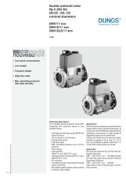
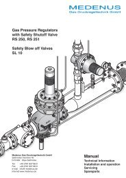
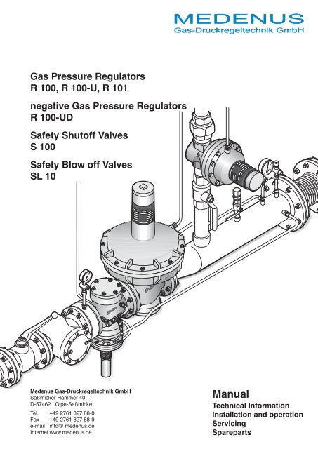
Gas Pressure Regulators<br />
R 100, R 100-U, R 101<br />
negative Gas Pressure Regulators<br />
R 100-UD<br />
Safety Shutoff Valves<br />
S 100<br />
Safety Blow off Valves<br />
SL 10<br />
uØ” —w W t<br />
0<br />
200<br />
mbar 400<br />
300<br />
2<br />
3<br />
1<br />
bar<br />
4<br />
Medenus Gas-Druckregeltechnik GmbH<br />
Saßmicker Hammer 40<br />
D-57462 Olpe-Saßmicke<br />
Tel. +49 2761 827 88-0<br />
Fax +49 2761 827 88-9<br />
e-mail info@ medenus.de<br />
Internet www.medenus.de<br />
<strong>Manual</strong><br />
Technical Information<br />
Installation and operation<br />
Servicing<br />
Spareparts
Conformity Certification<br />
(summary)<br />
Manufacturer: Medenus Gas-Druckregeltechnik GmbH<br />
Address: Saßmicker Hammer 40<br />
D-57462 Olpe-Saßmicke<br />
certifies that the products:<br />
R 100, R 100-U, R 100-UD, R 101<br />
Gas Pressure Regulator/Governor<br />
S 100 Savety Shutoff Valve<br />
SL 10 Savety Blow off Valve<br />
were submitted to an EC Type Examination and conform<br />
with the basic requirements of the directives<br />
90/396/EC EC Gas Appliances Directive<br />
in its valid version.<br />
For devices which are additionally marked with the CE<br />
sign a certification about the EC type examination is<br />
present referring to<br />
97/23/EC EC Pressure Equipment Directive<br />
Test report: CE 0085 File Number 06-0474-GEU<br />
Basis for the EC Type Examination are the harmonized<br />
European standards and/or national standards:<br />
DIN 3380 Regulator Group RG 10<br />
DIN 3381 Savety Shutoff Valve (SAV)<br />
shutoff group SG 10<br />
Marking (PIN) according Gas Appliances Directive<br />
CE-0085AQ0410 type R 100<br />
CE-0085AQ0881 type R 101<br />
CE-0085AQ0880 type S 100<br />
CE-0085AQ0879 type SL 10<br />
Marking according Pressure Equipment Directive<br />
The supervision of the quality assurance system is<br />
ensured by the DVGW.<br />
Olpe-Saßmicke,<br />
2006.07.14<br />
Martin Clemens<br />
Managing Director<br />
Basic language for translation of the manual is in<br />
German.<br />
Content<br />
1 Important instructions<br />
1.1 Guarantee and liability 3<br />
1.2 Symbols, instructions 3<br />
1.3 Abbrevations 3<br />
2 Safety information<br />
2.1 Dangers when using the equipment 3<br />
2.2 Personnel requirements 3<br />
2.3 local codes of practice 3<br />
2.4 Hand-over and operating instructions 3<br />
2.5 Safety in operation 3<br />
2.6 Actions when gas is smelt 3<br />
3 Technical descriptions<br />
3.1 R 100, R 101 Construction and function 4<br />
3.2 S 100 Construction and function 5<br />
3.3 SL 10 Construction and function 5<br />
3.4 Operating conditions 5<br />
3.5 Product-Specification 5<br />
3.6 R 100/R 101-Dimensions 6<br />
3.7 S 100-Dimensions 7<br />
3.8 SL 10-Dimensions 7<br />
3.9 Materials 7<br />
4 Installation S 100, R 100/R 101 and SL 10<br />
4.1 Basic gas train installation 8<br />
4.2 Installation into the gas train 9<br />
4.3 Works on the gas train 10<br />
4.4 Soundness test 10<br />
5 Commissioning and Operation<br />
5.1 Gas line filling and venting 10<br />
5.2 Set regulator/governor 11<br />
5.3 R-Spring removing and fitting 11<br />
5.4 Pressure checks 11<br />
5.5 R-Springs for outlet pressure P 2 12<br />
5.6 SL 10-Safety blow off valve springs 12<br />
5.7 S 100-High pressure setting 13<br />
5.8 S 100-Low setting 13<br />
5.9 SL 10-Setting 13<br />
5.10 S 100-Springs for MAX.-outlet pressure 14<br />
5.11 S 100-Springs for MIN.-outlet pressure 14<br />
5.12 S 100-shutoff and reset 14<br />
6 Faults, cause and rectification 15<br />
7 Servicing and repairs 15<br />
8 Replacement of parts<br />
8.1 Repairs 16<br />
8.2 Order data 16<br />
8.3 Replacement parts 16<br />
R 100 R 101<br />
S 100<br />
SL 10<br />
2
1 Important instructions<br />
The manual contains all Informations for authorized<br />
qualified personnel for correct assembly, commissioning,<br />
setting, servicing, fault finding and repairs.<br />
It is an integral part of the equipment and must be kept<br />
permanently on site.<br />
The notes and instructions must be followed at works<br />
with the equipment or the gas train.<br />
1.1 Guarantee and liability<br />
Liability will not be accepted or met any guarantee<br />
claims for personal injury or damage to property<br />
arising as a result of not paying attention to<br />
one or more of the causes below:<br />
• Use of the equipment as the intended conditions.<br />
• Proper assembly, commissioning, setting,<br />
operation and servicing of the equipment.<br />
• Operating the product only with correct installed<br />
and functioning safety and protection devices.<br />
• The instructions of assembly and operation of<br />
the equipment resp. the whole plant.<br />
• The servicing instructions.<br />
• Properly executed repairs.<br />
• Use of correct fuel gas.<br />
• No obstruction or damage of supply lines.<br />
• Use of original MEDENUS spare parts<br />
or<br />
• Force majuere.<br />
Strictly forbidden<br />
• Constructional alterations of the equipment.<br />
• Continued use despite the occurrence of a fault.<br />
1.2 Symbols, instructions<br />
In the manual symbols mark safety instructions to<br />
inform which, if not followed, could result:<br />
ATTENTION<br />
Damage of the device, the destruction<br />
of the plant or environmental damage.<br />
DANGER<br />
Serious injury to health or death.<br />
1.3 Abbrevations<br />
Abbrevations are explained as follows:<br />
P Gas pressure on inlet of regulator/governor<br />
1<br />
P Gas pressure on outlet of regulator/governor,<br />
controlled<br />
2<br />
V Flow rate (normal volume V N ) m 3 n/h<br />
SSV Safety shutoff Valve<br />
SBV Safety blow off Valve<br />
2 Safety informations<br />
2.1 Dangers when using the equipment<br />
MEDENUS-products correspond to the relevant<br />
existing standards and guidelines and the recognised<br />
safety laws.<br />
However, improper use of the devices could cause<br />
danger for the user or a third party, or result in<br />
damage of the device or plant.<br />
Therefore the equipment is only to be used<br />
• for its intended purpose<br />
• under proper conditions<br />
• with reference to the information of that installation<br />
and operating instruction as well as the<br />
inspection and servicing specifications which<br />
are valid for the effiency and safety of the whole<br />
plant.<br />
Malfunctions or faults must be rectified immediately.<br />
2.2 Personnel requirements<br />
Installation of the equipment should only be made<br />
by competent personnel.<br />
For setting and repairs only qualified persons are<br />
authorized.<br />
2.3 local codes of practice<br />
To local regulations and codes must be payed<br />
attention and observed, concerning<br />
• Gas lines, installation of the gas plant<br />
• Gas supply<br />
• Works on the gas plant<br />
• Safety guidelines.<br />
2.4 Hand-over and operating instructions<br />
The operating instruction shall be passed by the<br />
contractor to the operator of the gas plant prior to<br />
hand-over.<br />
The operator is to be informed that the manual<br />
must be kept carefully.<br />
2.5 Safety in operation<br />
The equipment is only to be used under correct<br />
working order of all safety devices.<br />
At least once a year the equipment should be<br />
checked by an agent of the contractor or qualified<br />
person for signs of visible damage and workability.<br />
Depending to plant conditions more frequent safety<br />
checks may be required.<br />
2.6 Actions when gas is smelt<br />
• Close gas shutoff valve.<br />
• Avoid open flame or spark generation by switching<br />
on electric units, lights, mobile phones etc.<br />
• Open windows and doors.<br />
• Warn all occupants and evacuate the building.<br />
• The appropriate gas installer or gas supplier is to<br />
be informed from outside the building.<br />
3
3 Technical descriptions<br />
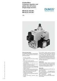
3.1 R 100 and R 101 Construction and function<br />
R 100 and R 101 are gas pressure regulators.<br />
Constant outlet pressure is ensured when the inlet<br />
pressure or flow capacity vary.<br />
The gas flows through the regulator housing in<br />
arrow direction. The main diaphragm is actuated<br />
via an impulse line from the outlet side by pressure.<br />
The required outlet pressure is adjusted at<br />
the spring.<br />
The valve remains open as long as the outlet pressure<br />
is below the set value. When reaching the set<br />
point the regulator valve closes.<br />
The measure work is directly mounted and operates<br />
independant from the inlet pressure.<br />
R 100 with double seat regulating valve.<br />
Nominal diameters: DN 50, 80, 100, 150, 200.<br />
R 101 with single seat valve<br />
Nominal diameters: DN 25, 40, 50, 65, 100.<br />
R 100-U Circulation regulators to limit pressure on<br />
gas pressure discharge plants. Gas flows back to<br />
the suction side of the compressor when the set<br />
opening pressure is exceeded.<br />
Nominal diameters: DN 50, 80, 100, 150, 200.<br />
R 100<br />
R 100-U<br />
4<br />
1<br />
2<br />
3<br />
4<br />
5<br />
7<br />
8<br />
7<br />
8<br />
9<br />
1<br />
2<br />
3<br />
R 100-UD negative pressure regulators control the<br />
gas throughput proportional to vacuum, f. e. of a<br />
gas motor or negative pressure gas appliance.<br />
Nominal diameters: DN 50, 80, 100, 150, 200.<br />
5<br />
R 101<br />
1<br />
2<br />
3<br />
4<br />
R 100-UD<br />
7<br />
8<br />
7<br />
8<br />
9<br />
4<br />
5<br />
6<br />
5<br />
3<br />
7<br />
8<br />
7<br />
8<br />
9<br />
7<br />
8<br />
9<br />
1 Pressure setting screw<br />
2 Setting spring<br />
3 Main diaphragm<br />
4 Vent connection<br />
5 Impulse connection<br />
6 Compensation<br />
diaphragm<br />
7 Regulator valve seat<br />
8 Single seat valve<br />
9 Cover<br />
4<br />
2<br />
1
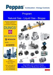
3.2 S 100 Construction and function<br />
S 100 safety shutoff valves (SSV) control a given<br />
gas pressure. They interrupt the gas flow at excess<br />
pressure or gas shortage automatically.<br />
S 100<br />
11<br />
12<br />
9<br />
10<br />
The diaphragm of the safety shutoff valve is actuated<br />
via an impulse line from the outlet side.<br />
When excess pressure or gas shortage lifts or<br />
drops the SSV spindle the latch lever reacts and<br />
the closing spring presses the valve disc against<br />
the valve seat.<br />
Nominal diameters: DN 25, 40, 50, 65, 80, 100,<br />
150, 200.<br />
13<br />
14<br />
5<br />
4<br />
4 Breathing connection<br />
5 Impulse connection<br />
9 Cover plate<br />
10 Valve for pressure<br />
compensation<br />
11 SSV valve seat<br />
12 SSV disc<br />
13 SSV closing spring<br />
14 SSV spindle<br />
15 Diaphragm disc<br />
16 SSV diaphragm<br />
17 Bearing<br />
18 Minimum pressure spring<br />
19 Maximum pressure spring<br />
20 Setting „excess pressure“<br />
21 Setting „low pressure“<br />
22 Reset button<br />
15<br />
20<br />
21<br />
22<br />
16<br />
17<br />
18<br />
19<br />
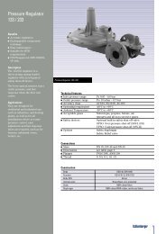
3.3 SL 10 Construction and function<br />
SL 10 safety blow off valves (SBV) prevents short<br />
pressure peaks infront of gas appliances or to<br />
avoid inadmissable high increase of pressure<br />
caused by leakage gas.<br />
The diaphragm of the SL 10 is actuated from down<br />
via an impulse bore by the inlet pressure.<br />
At excess pressure the measurement set opens<br />
the valve and blows off gas via the vent line.<br />
Nominal diameters: Rp 1”, 1½”, 2”<br />
SL 10<br />
8<br />
p 2<br />
1 2<br />
3<br />
4 5<br />
6 7<br />
1 Pressure setting screw<br />
2 Setting spring<br />
3 Diaphragm disc<br />
4 SBV diaphragm<br />
5 Impulse bore<br />
6 Regulating valve<br />
7 Valve seat, orifice V= …<br />
8 Breathing connection<br />
3.4 Operating conditions<br />
Inlet pressure P 1 max.<br />
R 100… DN 50 bis 150 4.0 bar<br />
R 100… DN 200 1.0 bar<br />
R 101 DN 25 8.0 bar<br />
R 101 DN 40 bis 100 4.0 bar<br />
S 100<br />
4.0 bar<br />
SL 10<br />
1.0 bar<br />
Outlet pressure P 2 max.<br />
R 100<br />
1.2 bar<br />
R 101<br />
750 mbar<br />
Gas characteristics - suitable for gas of the gas<br />
families 1, 2, 3 and other neutral gaseous media.<br />
Ambient temperature<br />
Fitting position<br />
Flow speed<br />
-20…+60°C<br />
any<br />
30 m/secs.<br />
(limit 50 m/secs.)<br />
Springs for R…-regulators, S 100 as well as for<br />
SL 10 are to be defined separately referring to the<br />
desired outlet resp. operating pressure P 2 .<br />
3.5 Product specification<br />
For dimensioning and construction the following<br />
operation data are required:<br />
1. Type of gas: ……………<br />
If not natural gas, characteristics are required<br />
2. Flow rate (normal volume V N )<br />
max. ……… m 3 n/h min. ……… m 3 n/h<br />
are to be converted into the volume of operating<br />
condition.<br />
3. Inlet pressure P 1<br />
max.……… bar min. ……… bar<br />
4. Outlet pressure P 2<br />
max. ……… bar min. ……… bar<br />
5. Closing pressure of the safety shutoff valve<br />
p max. ……… bar p min. ……… bar<br />
6. Safety blow off pressure (SL 10)<br />
p max. ……… bar p min. ……… bar<br />
7. Flow direction (right or left)<br />
5
3.6 Regulators R 100, R 100-U, R 100-UD, R 101 Types, Weights and Dimensions<br />
Type DN P 2 mbar ØD L A B X kg<br />
R 100/100-U 50 46…4100 160 250 398 115 600 12.0<br />
R 100/100-U 50 22… 975 275 250 372 115 582 14.0<br />
R 100/100-U 50 50… 400 385 250 372 115 582 18.0<br />
R 100/100-U 80 46…4100 160 280 415 139 625 17.0<br />
R 100/100-U 80 22… 975 275 280 391 139 601 19.0<br />
R 100/100-U 80 50… 400 385 280 391 139 601 23.0<br />
R 100/100-U 100 46…4100 160 300 428 152 638 21.0<br />
R 100/100-U 100 22… 975 275 300 404 152 614 23.0<br />
R 100/100-U 100 50… 400 385 300 404 152 614 27.0<br />
R 100/100-U 150 45…1800 275 380 694 195 1094 40.0<br />
R 100/100-U 150 16… 775 385 380 647 195 1047 45.0<br />
R 100/100-U 200 45…1800 275 420 723 245 1133 60.0<br />
R 100/100-U 200 16… 775 385 420 677 245 1077 65.0<br />
R 100, R 100-U, R 101 right<br />
B A<br />
X<br />
DN<br />
Rp 3/8<br />
P1 P2<br />
L<br />
R 101 25 46…4100 160 160 356 84 566 7.0<br />
R 101 25 30…1880 205 160 356 84 574 8.5<br />
R 101 25 6… 750 *318 160 346 84 556 10.5<br />
R 101 40 46…4100 160 160 356 83 566 11.0<br />
R 101 40 30…1880 205 160 364 83 574 12.5<br />
R 101 40 6… 750 *318 160 346 83 566 14.5<br />
R 101 50 30…1880 205 250 408 115 618 14.0<br />
R 101 50 22… 975 275 250 372 115 582 16.0<br />
R 101 50 50… 400 385 250 372 115 582 18.0<br />
R 101 65 30…1880 205 220 376 101 586 20.0<br />
R 101 65 22… 975 275 220 376 101 586 22.0<br />
R 101 65 50… 400 385 220 376 101 586 26.0<br />
R 101 100 22… 975 275 350 675 188 1075 33.0<br />
R 101 100 50… 400 385 350 661 188 1061 38.0<br />
R 101 100 13… 425 485 350 661 188 1061 45.0<br />
X<br />
A<br />
B<br />
Ø D<br />
R 100-UD right<br />
L<br />
DN<br />
Rp 3/8<br />
R 100-UD 50 160 250<br />
Spring ranges refer to individual order<br />
R 100-UD 50 275 250<br />
R 100-UD 50 385 250<br />
R 100-UD 80 160 280<br />
R 100-UD 80 275 280<br />
R 100-UD 80 385 280<br />
R 100-UD 100 160 300<br />
R 100-UD 100 275 300<br />
R 100-UD 100 385 300<br />
R 100-UD 150 275 380<br />
R 100-UD 150 385 380<br />
R 100-UD 200 275 420<br />
R 100-UD 200 385 420<br />
Dimensions on request<br />
P2<br />
P1 P2<br />
Ø D<br />
R 100/101 left R 100-UD left<br />
P1<br />
P2<br />
P1<br />
Ø D Diameter of regulator dome<br />
* 318 Diaphragm-Ø 284<br />
6
3.7 Safety shutoff valves S 100 Types, Weights and Dimensions<br />
Type DN ØD L A B X kg<br />
S 100 25 162 160 215 70 315 3.5<br />
S 100 40 162 160 230 100 330 5.0<br />
S 100 50 162 250 340 115 440 8.5<br />
S 100 65 162 220 330 110 430 7.0<br />
S 100 80 162 280 350 140 450 13.0<br />
S 100 100 162 300 360 150 510 15.0<br />
S 100 150 183 380 410 195 560 32.0<br />
S 100 200 183 420 460 240 610 49.0<br />
S 100 right left<br />
P1<br />
X<br />
A B<br />
Ø D<br />
L<br />
Rp 3/8 DN<br />
P1<br />
3.8 Safety blow off valves SL 10 Types, Weights and Dimensions<br />
Type Rp ØD L A B X kg<br />
SL 10 1 145 100 180 50 280 2.5<br />
SL 10 1 ½ 145 140 215 55 315 3.5<br />
SL 10 2 145 160 325 60 325 4.0<br />
SL 10<br />
Ø D<br />
Rp<br />
L<br />
X<br />
A<br />
B<br />
3.8 Materials R 100, R 101, S 100, SL 10<br />
Housing:<br />
Silumin casting<br />
Diaphragm cap: Silumin casting<br />
Internal parts:<br />
stainless<br />
Diaphragms:<br />
50 NBR<br />
Valve discs:<br />
50 NBR, vulcanized<br />
Connections DN 25-150 Flange PN 16 DIN 2533<br />
Connection DN 200 Flange PN 10 DIN 2532<br />
Thread Rp ISO 7/1<br />
7
1<br />
0<br />
2<br />
4<br />
3<br />
1<br />
0<br />
2<br />
4<br />
3<br />
0<br />
100<br />
0<br />
ä<br />
ß ut<br />
0<br />
ä<br />
4 Installation S 100, R 100/R 101 and SL 10<br />
4.1 Basic gas train installation<br />
R 100, R 101, S100, SL 10<br />
high pressure gas train<br />
system<br />
1 Gas line input<br />
2 Ball valve<br />
3 Filter<br />
4 intermediate collar<br />
5 Push button valve<br />
6 P 1 Manometer<br />
7 S 100 Safety shutoff valve<br />
8 S 100 breathing line<br />
9 S 100 impulse line<br />
10 Valve for pressure<br />
compensation<br />
8<br />
12<br />
ß ut<br />
uØ” —w<br />
Wt<br />
ä<br />
17<br />
16<br />
15<br />
14<br />
13<br />
19<br />
18<br />
uØ” —w W t<br />
20<br />
21<br />
100 100<br />
200<br />
400<br />
mbar<br />
300<br />
22<br />
23<br />
P2<br />
11<br />
3<br />
4<br />
5<br />
6<br />
bar<br />
R 100-U Circulation<br />
regulator system<br />
ß ut<br />
12<br />
2<br />
10<br />
uØ” —w<br />
Wt<br />
1<br />
7<br />
9<br />
P0<br />
14<br />
P1<br />
13<br />
* We recommend that all types of gas <strong>controls</strong><br />
are protected from contamination by the use<br />
of an appropriate in-line gas filter.<br />
100<br />
200<br />
mbar 400<br />
300<br />
20<br />
11<br />
26<br />
P1<br />
25<br />
24<br />
R 100-UD negative pressure<br />
regulator system<br />
1<br />
4<br />
5<br />
12<br />
6<br />
bar<br />
20<br />
14<br />
13<br />
11<br />
200<br />
mbar 400<br />
300<br />
P2<br />
11 Pressure stabilising section<br />
12 Regulator<br />
13 Regulator impulse line<br />
14 Regulator breathing line<br />
15 SSV test valve<br />
16 SL 10 Safety blow off valve (SBV)<br />
17 SL 10 Blow off line<br />
18 SL 10 Breathing line<br />
19 Vent valve<br />
20 P 2 Manometer<br />
21 Test burner<br />
22 Compensator<br />
23 P 2 Flange connection<br />
P1<br />
ß ut<br />
uØ” —w<br />
Wt<br />
ä<br />
24 Compressor<br />
25 Relief valve<br />
26 Bypass<br />
8
0<br />
1<br />
0<br />
2<br />
4<br />
3<br />
X<br />
X<br />
X<br />
X<br />
ä<br />
ß ut<br />
0<br />
0<br />
4.2 Installation into the gas train<br />
P1<br />
DN R<br />
8<br />
ß ut<br />
uØ” —w<br />
Wt<br />
14<br />
13<br />
ä<br />
17<br />
14<br />
13<br />
9<br />
ß ut<br />
uØ” —w<br />
Wt<br />
ä<br />
18<br />
20<br />
uØ” —w W t<br />
100<br />
200<br />
mbar 400<br />
300<br />
≥ 10 x DN R<br />
≥ 5 x DN P2<br />
P2<br />
DN P2<br />
• Before installation of the equipment<br />
the capacity data (type<br />
plate) and the extend of supply<br />
must be checked and compared<br />
with the order data.<br />
Customers should ensure that<br />
the goods are suitable for their<br />
purpose.<br />
• The gas inlet pressure must be<br />
below the max. permissible<br />
pressure of the regulator and<br />
its appliances connected in series.<br />
• Pay attention to the gas flow<br />
direction ➼ of the appliance.<br />
• Remove the protection of the<br />
flange connection.<br />
• Take notice of tension-free<br />
assembly of all flange connections<br />
and pipes.<br />
• Tighten screws diagonally<br />
opposite.<br />
• Vent lines of regulator, S 100<br />
and SL 10 must be installed<br />
separately and leading to safe<br />
open atmosphere.<br />
• The gas train should not come<br />
into contact with curing<br />
masonry, concrete walls and<br />
floors are not admissible.<br />
• Take care of minimum distances<br />
“X” and “Y” for regulator<br />
and S 100 adjustment.<br />
• Fit the gas train with suitable<br />
supports.<br />
P1<br />
100<br />
200<br />
mbar 400<br />
300<br />
20<br />
≥ 10 x DN R<br />
• The length of the pressure<br />
stabilising section shall be<br />
5 times longer than the<br />
“DN P 2 “ pipe diameter.<br />
DN R<br />
12<br />
20<br />
14<br />
13<br />
11<br />
100<br />
200<br />
mbar 400<br />
300<br />
P2<br />
DN P2<br />
• Impulse lines for regulator and<br />
S 100:<br />
Steel tube Ø 12 x 1.<br />
• Distance of the test points for<br />
impulse lines from regulator<br />
and safety shutoff valve<br />
approx. 10 times “DN R” , i. e.<br />
regulator nominal diameter.<br />
1<br />
4<br />
5<br />
6<br />
bar<br />
≥ 10 x DN R<br />
≥ 5 x DN P2<br />
P1<br />
DN R<br />
ß ut<br />
uØ” —w<br />
Wt<br />
ä<br />
9<br />
8 S 100 breathing line<br />
9 S 100 impulse line<br />
11 Pressure stabilising section<br />
13 Regulator impulse line<br />
14 Regulator breathing line<br />
17 SL 10 blow off line<br />
18 SL 10 breathing line<br />
20 P 2 Manometer
0<br />
0<br />
4.3 Works on the gas train<br />
• In principle only well instructed personel is authoriced<br />
to work on the gas train.<br />
• Never work on the appliance under gas pressure<br />
or under electrical power.<br />
• Avoid open flames.<br />
• Observe local safety regulations.<br />
• Only tested and approved sealing material should<br />
be used.<br />
Take notice of the user instructions!<br />
• Allways use new seals after removal or exchange<br />
of parts.<br />
• Having finished works on the gas train:<br />
Check function and tightness.<br />
Not following these instructions could result<br />
damages to persons, property or environment.<br />
4.4 Soundness test<br />
Before setting into operation or after service on appliances<br />
and fittings the complete gas train is to be<br />
soundness checked.<br />
• Close the ball valve infront the gas train.<br />
• Close following shut off devices (solenoid resp.<br />
pneumatic valves).<br />
• If the test pressure exceeds the blow off pressure<br />
of the SL 10, close the line infront of the SL 10.<br />
• Connect the test assembly to test points infront<br />
and behind the regulating device.<br />
• Test with air:<br />
- Test pressure ≥ P 2 x 1.5<br />
- Waiting time for pressure<br />
equalisation<br />
5 minutes<br />
- Test duration 5 minutes<br />
- max. permissible pressure loss 1 mbar<br />
• Following the soundness test:<br />
Open the ball valve of the SL 10 line.<br />
5 Commissioning and Operation<br />
5.1 Gas line filling and venting<br />
Prior to commissioning of the gas appliance the<br />
gas train must be purged/vented:<br />
5.1.1 Open the ball valve 2 in the gas supply (P 1 )<br />
slowly.<br />
5.1.2 Open the valve for pressure compensation 0 of<br />
the regulator to fill it and to set the gas train under<br />
pressure.<br />
5.1.4 Close the the valve for pressure compensation 0<br />
(return spring closes automatically).<br />
5.1.5 Reset the S 100 by pulling the reset pull button.<br />
2<br />
3<br />
11<br />
bar<br />
4<br />
2<br />
3<br />
1<br />
bar<br />
4<br />
2<br />
10<br />
5.1.6 Screw on the protection cap of the S 100.<br />
5.1.3 Remove the protection cap of the safety shutoff<br />
valve 7 (S 100).<br />
7<br />
10<br />
10
ß ut<br />
uØ” —w W t<br />
ä<br />
ß ut<br />
ä<br />
ä<br />
Wt<br />
ß ut<br />
ä<br />
ä<br />
0<br />
0<br />
ä<br />
5.1.7 Vent the gas train via hose o to safe atmosphere<br />
and check by means of the test burner a.<br />
Dont use the test burner for venting!<br />
19<br />
21<br />
5.3 R-Spring removing and fitting<br />
If the setting of the required outlet pressure is not possible<br />
check the range of the spring and change the<br />
spring if necessary.<br />
5.3.1 Remove the regulator cap,<br />
turn out the setting screw,<br />
pull out the setting disc with ball and spring,<br />
exchange the spring for a suitable one.<br />
200<br />
300<br />
uØ” —w<br />
100<br />
0<br />
mbar 400<br />
15<br />
Air or inert gas should be expelled fully and the<br />
gas train filled with gas.<br />
5.1.8 Close Vent valve t and refit cover cap.<br />
15<br />
5.3.2 Fit setting disc with ball and setting screw.<br />
5.2 Set regulator/governor<br />
Prior to commissing use the the test burner to measure<br />
the available pressure and preset the regulator.<br />
Set the regulator outlet pressure P 2 under maximum<br />
gas consumption during operation:<br />
5.2.1 Remove the regulator cap.<br />
5.3.3 Adjust the required outlet/flow pressure.<br />
5.3.4 Screw on the regulator cap.<br />
5.4 Pressure checks<br />
5.4.1 Measurement of the static pressure when the gas<br />
appliance is switched off<br />
6 P 1 open the manometer on regulator inlet and<br />
note the pressure<br />
p P 2 open the manometer on regulator outlet and<br />
note the pressure.<br />
ß ut<br />
uØ” —w W t<br />
5.2.2 Turn the setting screw with a screwdriver:<br />
to right pressure increase<br />
to left<br />
pressure reduction<br />
ä<br />
5.4.2 Measurement of the dynamic pressure during<br />
operation - at Min.- and Max.-Load<br />
6 P 1 open the manometer on regulator inlet and<br />
note the pressure<br />
p P 2 open the manometer on regulator outlet and<br />
note the pressure.<br />
20 P2<br />
200<br />
300<br />
100<br />
mbar 400<br />
P1<br />
6<br />
1<br />
2<br />
bar<br />
4<br />
3<br />
uØ” —w<br />
Wt<br />
5.2.3 Screw on the regulator cap.<br />
11
TT<br />
5.5 Regulator springs for outlet pressure P 2 -setting, spring data<br />
R 100 - DN 50/80/100, R 101 - DN 25/40/50/65 Diaphragm Diameter T = 16 - 39 - 62 mm *<br />
D 160 Ø D 205 Ø D 275 Ø D 318 Ø D 385 Ø Spring Data<br />
x 10 20 30 10 20 30 10 20 30 10 20 30 10 20 30 L0 Øm øs Z<br />
Spring mbar mbar mbar mbar mbar mm mm mm<br />
FA 01 46 52 60 30 36 38 22 23 25 6 7 8 10 11 12 200 40.0 2.5 37<br />
FA 02 54 62 72 35 40 44 24 25 27 7 9 10 11 12 13 200 40.0 2.5 25<br />
FA 03 60 70 83 40 46 52 26 28 32 9 11 13 12 13 15 205 40.0 2.5 17.3<br />
FA 04 70 90 108 45 55 64 30 33 38 11 14 17 13 15 17 205 40.0 2.5 12.2<br />
FA 05 90 120 150 50 62 76 34 40 47 14 19 24 15 19 21 205 40.0 3.5 26.3<br />
FA 06 120 164 208 60 80 103 40 50 60 20 28 36 19 23 27 205 40.0 3.5 18.1<br />
FA 07 160 220 290 76 108 140 52 67 82 27 38 50 23 29 35 205 40.0 3.5 12.6<br />
FA 08 225 325 415 110 156 206 70 90 115 39 58 78 30 40 50 205 40.0 4.0 13.6<br />
FA 09 325 473 620 147 222 302 90 123 160 55 82 110 36 50 65 205 40.0 5.0 19.5<br />
FA 10 472 695 922 205 320 425 130 183 238 82 123 165 54 75 100 205 40.0 5.3 16.3<br />
FA 11 700 1040 1385 300 450 634 185 265 345 123 187 255 80 110 145 205 40.0 6.0 16.4<br />
FA 12 980 1489 2020 390 645 900 253 373 490 167 267 365 105 155 205 200 40.0 6.5 15.2<br />
FA 13 1670 2435 3250 700 1070 1462 400 580 760 300 450 590 170 243 325 205 40.0 7.0 12.8<br />
FA 14 1650 2800 4100 670 1250 1880 405 680 975 300 520 750 175 290 400 190 40.0 7.5 11.2<br />
x = number of right turns to increase the pressure up to … mbar<br />
R 100 - DN 150/200, R 101 - DN 80/100 T = 80-130 mm *<br />
Diaphragm Diameter<br />
Spring Data<br />
Spring D 275 Ø D 385 Ø D 485 Ø L0 Øm øs Z<br />
No. mbar mbar mbar mm mm mm<br />
F 70 45 50 16 25 13 15 400 62.5 3.5 13<br />
F 71 50 80 20 30 15 20 400 62.5 4.0 13<br />
F 711 80 110 30 44 20 28 400 64.0 5.0 15<br />
F 72 110 160 44 68 28 42 400 64.0 6.0 16<br />
F 73 140 240 58 90 36 54 400 64.0 6.0 12<br />
F 73A 200 300 71 120 43 65 400 64.5 6.5 13<br />
F 74 260 340 98 140 52 81 400 64.0 7.0 13<br />
F 74A 300 400 111 178 65 101 400 64.0 7.5 13<br />
F 742 400 500 138 223 79 126 400 64.0 8.0 13<br />
F 742A 480 580 170 275 97 154 400 64.0 8.5 13<br />
F 743 560 760 206 337 117 188 400 64.0 9.0 13<br />
F 743A 700 900 270 443 151 245 400 63.0 9.5 13<br />
F 78* 880 1400 369 608 205 335 400 59.5 10.5 15<br />
F 76A* 1150 1800 469 775 260 425 400 58.0 11.0 15<br />
5.6 SL 10 Safety blow off valve springs<br />
Spring<br />
No.<br />
Min. Max. L0 Øm øs Z<br />
mbar mbar mm mm mm<br />
F100 B 20 50 90 31 2.0 11/13<br />
F100 B 25 80 90 32 2.5 12/14<br />
F101 40 150 90 33 3.0 12/14<br />
F102 60 330 90 34 3.5 11/13<br />
F104 110 600 90 34 4.0 5.5/7<br />
F105 450 1050 90 34 4.0 7/9<br />
F106 700 1800 90 36 5.0 8/10<br />
12<br />
T *<br />
L0<br />
Øm<br />
øs<br />
Z<br />
Screw-in depth in mm<br />
L0<br />
Øm<br />
Length of spring<br />
Spring inside diameter<br />
Spring wire diameter<br />
Number of spring windings<br />
* FA 12, FA 13, FA 14, F 78, F 76A<br />
with high pressure screw spindle<br />
F 104 HD-design (high pressure) from 400 mbar<br />
F 105 and F 106 HD-design for high pressure<br />
R 100-U, R 100-UD Springs on request.<br />
sø
ä<br />
Wt<br />
ä<br />
Wt<br />
5.7 S 100 - High setting (safety shutoff)<br />
The SSV 7 reacts immediately when the maximum<br />
permissable gas outlet pressure P 2 will be<br />
exceeded. The safety shutoff valve S 100 closes<br />
and interrupts the gas supply to the regulator.<br />
5.7.1 Test of the maximum shutoff pressure.<br />
• with switched off plant and<br />
• the ball valve t of the SBV closed.<br />
• increase the gas pressure on the regulator<br />
higher than P 2 until the S 100 reacts.<br />
5.8 S 100 - Low setting<br />
In case the S 100 device is equipped with a shutoff<br />
function at gas pressure fault, it is to be set in<br />
accordance to the operation conditions-<br />
Minimum setting not below P 2<br />
= 10 mbar.<br />
5.8.1 Unscrew the cover cap of the SSV and set the<br />
inner setting screw a and spring i by means<br />
of a screwdriver with turning:<br />
- to right pressure increase<br />
- to left pressure reduction<br />
Following to the setting of the SSV<br />
screw on the cover cap.<br />
16<br />
16<br />
uØ” —w<br />
—w<br />
15<br />
15<br />
5.9 SL 10 setting<br />
The blow off pressure of the SBV should be set<br />
approx. 20 % less than the SSV max.-setting.<br />
The SBV equalises shortterm pressure peaks or<br />
avoids inadmissable high increase of pressure<br />
caused by leakage gas.<br />
After the test<br />
• open the SBV ball valve t again!<br />
• readjust the pressure on the regulator to P 2 .<br />
5.9.1 Unscrew the cover cap of the SBV z.<br />
17<br />
5.7.2 Correction of the excess pressure setting<br />
may be necessary when the presetting is too low<br />
or too high referring to the outlet pressure P 2<br />
during operation.<br />
Recommended response pressures at<br />
P 2 ≤ 100 mbar —> P 2 + 50 mbar<br />
P 2 > 100 - 200 mbar —> P 2 + 100 mbar<br />
P 2 > 200 mbar —> P 2 x 1.5<br />
The shutoff pressure must be below the highest<br />
permissable operation pressure of the appliances<br />
connected in series.<br />
The SSV should not react following a controlled<br />
shutdown or lockout of the gas plant.<br />
5.7.3 Unscrew the cover cap of the S 100 and set the<br />
outer setting screw p and spring o by means<br />
of a screwdriver with turning:<br />
- to right pressure increase<br />
- to left pressure reduction<br />
16<br />
15<br />
5.9.2 Set the setting screw and spring by means<br />
of a screwdriver with turning:<br />
- to right pressure increase<br />
- to left pressure reduction<br />
MEDENUS Gas-Druckregelgerät<br />
100<br />
0<br />
200<br />
mbar 400<br />
300<br />
16<br />
200<br />
300<br />
15<br />
MEDENUS Gas-Druckregelgerät<br />
100<br />
0<br />
mbar 400<br />
18<br />
19<br />
20<br />
21<br />
13<br />
Following to the setting of the SBV screw on the<br />
cover cap.
T<br />
L0<br />
sø<br />
5.10 SAV Springs for S 100-25/40/50/65/80/100/125<br />
GMB 135-7 MAXIMUM safety valve shutoff<br />
Spring SAV MD SAV MD-R Spring data<br />
T mm* 8 15 8 15<br />
No.<br />
Min. Max. Min. Max. L0 Øm øs Z<br />
mbar mbar mbar mbar mm mm mm<br />
F 96 40 50 60 30,5 2,0 6/8<br />
F 97 50 80 60 30,5 2,5 8/10<br />
F 97 A 90 140 250 350 60 31,3 2,8 9/11<br />
F 95 130 190 350 500 60 32,0 3,0 8/10<br />
F 95 A 170 250 450 700 60 32,2 3,2 8/10<br />
F 94 250 360 700 1000 60 32,5 3,5 8/10<br />
F 94 A 1100 1500 60 34,0 4,0 8/10<br />
F 94 AB 1250 2000 55 34,5 4,5 5/7<br />
GMB 135-7 MINIMUM safety valve shutoff<br />
Spring SAV MD SAV MD-R Spring data<br />
* * 1 4 1 4<br />
No.<br />
Min. Max. Min. Max. L0 Øm øs Z<br />
mbar mbar mbar mbar mm mm mm<br />
F 93 10 15 30 50 28 11,0 1,0 8/10<br />
F 93 B 15 20 50 80 28 11,0 1,0 8/9<br />
F 92 B 20 25 85 105 28 11,0 1,0 7/9<br />
F 92 C 25 30 90 120 28 11,1 1,1 7/9<br />
F 92 40 60 150 200 28 11,2 1,2 7/9<br />
F 91 120 165 290 400 28 11,5 1,5 6/8<br />
5.11 SAV Springs for S 100-150/200<br />
GMB 146 MAXIMUM safety valve shutoff<br />
Spring SAV MD SAV MD-R Spring data<br />
T mm* 8 23 8 23<br />
No.<br />
Min. Max. Min. Max. L0 Øm øs Z<br />
mbar mbar mbar mbar mm mm mm<br />
F 38 B 15 50 90 210 65 33,5 2,5 5/7<br />
F 38 25 90 150 380 65 34,0 3,0 5/7<br />
F 39 45 135 200 540 65 34,0 3,5 6/8<br />
F 40 70 260 290 980 65 35,0 4,0 5/7<br />
F 41 120 335 450 1240 65 35,0 4,0 4/6<br />
GMB 146 MINIMUM safety valve shutoff<br />
Spring SAV MD SAV MD-R Spring data<br />
* * 1 4 1 4<br />
No.<br />
Min. Max. Min. Max. L0 Øm øs Z<br />
mbar mbar mbar mbar mm mm mm<br />
F 46 10 30 40 125 30 18,0 1,5 3/5<br />
F 45 15 40 50 175 30 18,0 1,5 4/6<br />
F 47 20 90 50 380 25 18,5 2,0 3/5<br />
F 471 45 110 200 460 30 18,5 2,0 3/5<br />
F 48 70 190 200 820 25 19,0 2,5 3/5<br />
T mm* Screw-in depth<br />
** Turns<br />
Øm<br />
GMB 186 MAXIMUM safety valve shutoff<br />
Spring<br />
Spring data<br />
T mm* 8 19 8 15<br />
No.<br />
Min. Max. Min. Max. L0 Øm øs Z<br />
mbar mbar mbar mbar mm mm mm<br />
F 96 10 20 60 30,5 2,0 6/8<br />
F 97 17 38 60 30,5 2,5 8/10<br />
F 97 A 38 65 60 31,3 2,8 9/11<br />
F 95 50 96 60 32,0 3,0 8/10<br />
F 95 A 70 125 60 32,2 3,2 8/10<br />
F 94 100 150 60 32,5 3,5 8/10<br />
GMB 186 MINIMUM safety valve shutoff<br />
Spring<br />
Spring data<br />
* * 1 4<br />
No.<br />
Min. Max. L0 Øm øs Z<br />
mbar mbar mm mm mm<br />
F 93 B 5 8 28 11,0 1,0 8/10<br />
F 92 B 10 15 28 11,0 1,0 7/9<br />
F 92 C 10 15 28 11,1 1,1 7/9<br />
F 92 15 25 28 11,2 1,2 7/9<br />
F 91 52 75 28 11,5 1,5 6/8<br />
5.12 S 100 shutoff<br />
Following to excessive<br />
(or falling below)<br />
permissable shutoff<br />
pressure the gas flow<br />
will be interrupted.<br />
The S 100 must be<br />
reset by hand.<br />
5.12.1 Reset as described on page 10:<br />
5.1.2 Open the valve for pressure compensation of<br />
the regulator to fill it and to set the gas train under<br />
pressure.<br />
5.1.3 Remove the protection cap of the S 100.<br />
5.1.4 Close the the valve for pressure compensation.<br />
5.1.5 Reset the S 100 by pulling the reset pull button.<br />
5.1.6 Screw on the protection cap of the S 100.<br />
14
6 Faults Cause and rectification<br />
ʘ Extreme P 2 pressure drop when max. flow rate,<br />
full load capacity cannot be reached, P1 is constant<br />
ʘ Extreme P 2 pressure drop when max. flow rate,<br />
supply pressure P1 drops down<br />
ʘ Heavy P 2 variations of pressure (pulsation)<br />
ʘ Loud gas flow noise<br />
ʘ Regulator does not work, blocks (does not open)<br />
ʘ Regulator blows off during operation<br />
ʘ Noise of regulator<br />
ʘ S 100 shuts off often<br />
Spring or size of regulator not correct. Check dimensions<br />
of spring and regulator, possibly exchange.<br />
Gas supply pressure is not sufficiant. Increase supply<br />
pressure. Pipe cross section too small (too much pressure<br />
loss in gas supply), check<br />
Setting of gas consumption appliance, check range of<br />
spring possibly size of regulator, impulse line.<br />
Speed of gas too high, check size of regulator.<br />
Leakage of the compensation diaphragm, exchange.<br />
Main diaphragm, screwing in the regulator leakageexchange.<br />
Mechanical wear of the regulator spindle, exchange of<br />
the measure work.<br />
Setting of S 100 too low resp. SL 10 too high, correction.<br />
7 Servicing and repairs<br />
The servicing specifications of the installer of<br />
the plant as well as the safety guidelines<br />
given on page 2 of the manual should be<br />
observed.<br />
R regulators, S 100 SSV and SL 10 SBV need no<br />
service except wear parts.<br />
Diaphrams are to be checked for their condition.<br />
The side of the textile must be placed on the<br />
opposite side to the pressure side. The measure<br />
work may not be wrenched to avoid any diagonal<br />
wrinkle.<br />
Valve discs are to be checked for dirt and damage.<br />
When installing the regulator valve disc the spindle<br />
is to be secured from torsion.<br />
In principle should be observed:<br />
• Exchange of faulty components only with<br />
original MEDENUS parts.<br />
• Seal joints on flange connections or screwings<br />
which were opened for service works, are to be<br />
cleaned prior to re-installation.<br />
Take care of correct connections.<br />
• Replace damaged seals.<br />
• Test tightness following service works and<br />
• Check function and setting values!<br />
15
8 Replacement of parts<br />
8.1 Repairs<br />
For replacement only persons fitted with the<br />
special qualification are authorized.<br />
8.2 Order data for replacement parts<br />
required data -refferring to type plate-<br />
• Replacement part Description (Pos. No.)<br />
• SSV/Regulator-/SBV-Type S100/R100/R101/SL10<br />
• Nominal Diameter DN<br />
• Production-No. No. …<br />
• Year of construction ………<br />
• Inlet pressure P 1 bar<br />
• Outlet pressure P 2 mbar<br />
• Type of gas ………<br />
8.3 Replacement parts<br />
9<br />
8<br />
9<br />
8<br />
R 100 R 101<br />
R 100-U<br />
S 100<br />
13<br />
12<br />
13<br />
12<br />
1<br />
2<br />
3<br />
4<br />
5<br />
6<br />
7<br />
1<br />
2<br />
4<br />
5<br />
3<br />
6<br />
7<br />
SL 10<br />
1<br />
2<br />
11<br />
10<br />
4<br />
5<br />
6<br />
8<br />
7<br />
1<br />
2<br />
4<br />
5<br />
3<br />
6<br />
7<br />
9<br />
8<br />
R 101-UD<br />
12<br />
13<br />
Pos. Description<br />
1 R main diaphragm<br />
2 O-ring R-1<br />
3 O-ring R-2<br />
4 O-ring R-3<br />
5 O-ring R-4<br />
6 R valve disc<br />
7 O-ring R-5<br />
8 O-ring R-6<br />
9 O-ring R-7<br />
0 R101 Compensation<br />
diaphragm<br />
q R101 O-ring R-8<br />
w O-Ring R-9<br />
é O-Ring R-10<br />
w<br />
t<br />
z<br />
u<br />
i<br />
S100 diaphragm<br />
S100 valve disc<br />
O-Ring-S100-1<br />
O-Ring-S100-2<br />
O-Ring-S100-3<br />
o SL10 diaphragm<br />
p SL10 O-ring 1<br />
a SL10 valve disc<br />
s SL10 O-ring 2<br />
d SL10 O-ring 3<br />
Complete sets<br />
incl. O-rings:<br />
R100 repair kit<br />
R100-U repair kit<br />
R100-UD repair kit<br />
R101 repair kit<br />
S100 repair kit<br />
SL10 repair kit<br />
17<br />
23<br />
15<br />
16<br />
17<br />
14<br />
18<br />
19<br />
20<br />
21<br />
22<br />
MEDENUS pressure regulators R100/101, S100, SL10 Edition 11.2007 Print no.: R100-manual.e-G+T<br />
Rights of modification reserved.<br />
All rights reserved.<br />
16