Manual - Peppas Ltd Combustion - energy controls
Manual - Peppas Ltd Combustion - energy controls
Manual - Peppas Ltd Combustion - energy controls

You also want an ePaper? Increase the reach of your titles
YUMPU automatically turns print PDFs into web optimized ePapers that Google loves.
1<br />
0<br />
2<br />
4<br />
3<br />
1<br />
0<br />
2<br />
4<br />
3<br />
0<br />
100<br />
0<br />
ä<br />
ß ut<br />
0<br />
ä<br />
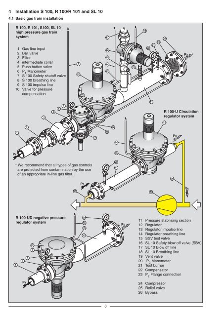
4 Installation S 100, R 100/R 101 and SL 10<br />
4.1 Basic gas train installation<br />
R 100, R 101, S100, SL 10<br />
high pressure gas train<br />
system<br />
1 Gas line input<br />
2 Ball valve<br />
3 Filter<br />
4 intermediate collar<br />
5 Push button valve<br />
6 P 1 Manometer<br />
7 S 100 Safety shutoff valve<br />
8 S 100 breathing line<br />
9 S 100 impulse line<br />
10 Valve for pressure<br />
compensation<br />
8<br />
12<br />
ß ut<br />
uØ” —w<br />
Wt<br />
ä<br />
17<br />
16<br />
15<br />
14<br />
13<br />
19<br />
18<br />
uØ” —w W t<br />
20<br />
21<br />
100 100<br />
200<br />
400<br />
mbar<br />
300<br />
22<br />
23<br />
P2<br />
11<br />
3<br />
4<br />
5<br />
6<br />
bar<br />
R 100-U Circulation<br />
regulator system<br />
ß ut<br />
12<br />
2<br />
10<br />
uØ” —w<br />
Wt<br />
1<br />
7<br />
9<br />
P0<br />
14<br />
P1<br />
13<br />
* We recommend that all types of gas <strong>controls</strong><br />
are protected from contamination by the use<br />
of an appropriate in-line gas filter.<br />
100<br />
200<br />
mbar 400<br />
300<br />
20<br />
11<br />
26<br />
P1<br />
25<br />
24<br />
R 100-UD negative pressure<br />
regulator system<br />
1<br />
4<br />
5<br />
12<br />
6<br />
bar<br />
20<br />
14<br />
13<br />
11<br />
200<br />
mbar 400<br />
300<br />
P2<br />
11 Pressure stabilising section<br />
12 Regulator<br />
13 Regulator impulse line<br />
14 Regulator breathing line<br />
15 SSV test valve<br />
16 SL 10 Safety blow off valve (SBV)<br />
17 SL 10 Blow off line<br />
18 SL 10 Breathing line<br />
19 Vent valve<br />
20 P 2 Manometer<br />
21 Test burner<br />
22 Compensator<br />
23 P 2 Flange connection<br />
P1<br />
ß ut<br />
uØ” —w<br />
Wt<br />
ä<br />
24 Compressor<br />
25 Relief valve<br />
26 Bypass<br />
8