403 B01 MB-D(LE) 053 B01 - Peppas Ltd Combustion - energy ...
403 B01 MB-D(LE) 053 B01 - Peppas Ltd Combustion - energy ...
403 B01 MB-D(LE) 053 B01 - Peppas Ltd Combustion - energy ...

You also want an ePaper? Increase the reach of your titles
YUMPU automatically turns print PDFs into web optimized ePapers that Google loves.
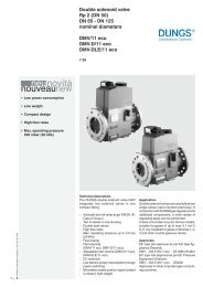
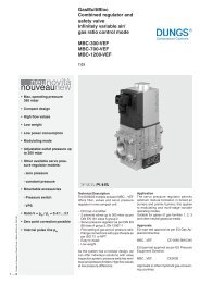
GasMultiBloc<br />
Combined regulator and<br />
safety shut-off valves<br />
Single-stage function<br />
<strong>MB</strong>-D(<strong>LE</strong>) <strong>403</strong> <strong>B01</strong><br />
<strong>MB</strong>-D(<strong>LE</strong>) <strong>053</strong> <strong>B01</strong><br />
7.20<br />
Printed in Germany • Rösler Druck • Edition 02.08 • Nr. 214 765<br />
1 … 6<br />
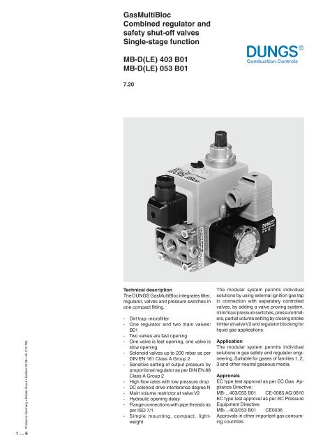
Technical description<br />
The DUNGS GasMultiBloc integrates filter,<br />
regulator, valves and pressure switches in<br />
one compact fitting.<br />
- Dirt trap: microfilter<br />
- One regulator and two main valves:<br />
<strong>B01</strong><br />
- Two valves are fast opening<br />
- One valve is fast opening, one valve is<br />
slow opening<br />
- Solenoid valves up to 200 mbar as per<br />
DIN EN 161 Class A Group 2<br />
- Sensitive setting of output pressure by<br />
proportional regulator as per DIN EN 88<br />
Class A Group 2<br />
- High flow rates with low pressure drop<br />
- DC solenoid drive interference degree N<br />
- Main volume restrictor at valve V2<br />
- Hydraulic opening delay<br />
- Flange connections with pipe threads as<br />
per ISO 7/1<br />
- Simple mounting, compact, lightweight<br />
The modular system permits individual<br />
solutions by using external ignition gas tap<br />
in connection with separately controlled<br />
valves, by adding a valve proving system,<br />
mini/maxi pressure switches, pressure limiters,<br />
partial volume setting by closing stroke<br />
limiter at valve V2 and regulator blocking for<br />
liquid gas applications.<br />
Application<br />
The modular system permits individual<br />
solutions in gas safety and regulator engineering.<br />
Suitable for gases of families 1, 2,<br />
3 and other neutral gaseous media.<br />
Approvals<br />
EC type test approval as per EC Gas Appliance<br />
Directive:<br />
<strong>MB</strong>-...<strong>403</strong>/<strong>053</strong> <strong>B01</strong> CE-0085 AQ 0810<br />
EC type test approval as per EC Pressure<br />
Equipment Directive:<br />
<strong>MB</strong>-...<strong>403</strong>/<strong>053</strong> <strong>B01</strong> CE0036<br />
Approvals in other important gas consuming<br />
countries.
Functional description of gas flow<br />
1. When the valves V1 and V2 are<br />
closed, chamber A is under inlet<br />
pressure.<br />
2. A hole D in the filter housing connects<br />
min. pressure switch with<br />
chamber A. If the inlet pressure<br />
applied to the pressure switch exceeds<br />
the incoming reference value,<br />
it switches through to the automatic<br />
burner control.<br />
3. After release by the automatic burner<br />
control, valves V1 and V2 open.<br />
The gas flows through chambers A,<br />
B and C of the GasMultiBloc.<br />
Operating method of valve-regulator<br />
combination on valve V1<br />
A regulator, compensating for residual<br />
pressure is integrated in valve V1 (pressure<br />
regulating part). Armature 7 is not<br />
connected to valve plate unit 3. When<br />
it opens, armature 7 pretensions compression<br />
spring (V1) 5 and releases<br />
the valve plate unit. When the valve<br />
closes, the armature acts directly on<br />
the valve plate unit. The output pressure<br />
upstream of valve V2 is defined<br />
by pretensioning regulating spring 8<br />
(tension spring) via setting screw 16.<br />
The output pressure acts via opening E<br />
on the working diaphragm of regulator<br />
part 1. In regulated state, setting spring<br />
inlet pressure and pressure of working<br />
diaphragm are in force equilibrium.<br />
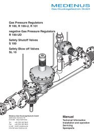
Sectional drawing of <strong>MB</strong>-D<strong>LE</strong>...<br />
10<br />
9<br />
8<br />
7<br />
6<br />
5<br />
4<br />
3<br />
2<br />
1<br />
1 Pressure regulator<br />
2 Microfilter<br />
3 Valve V1<br />
4 Connection flange<br />
5 Closing spring V1<br />
6 Housing<br />
7 Armature V1<br />
16<br />
17<br />
V1<br />
V2<br />
p 1 p 2<br />
A<br />
B<br />
E<br />
18 19<br />
C<br />
8 Regulating spring<br />
9 Solenoid V1<br />
10 Electrical connection<br />
11 Valve V2<br />
12 Closing spring V2<br />
13 Armature V2<br />
14 Solenoid V2<br />
15<br />
14<br />
13<br />
12<br />
11<br />
15 Solenoid housing<br />
Setting:<br />
16 - Gas pressure p a<br />
17 - Main volume<br />
18 - Fast stroke<br />
19 Hydraulic brake<br />
Operating method of valve V2<br />
Armature 13 of valve V2 is connected to<br />
valve plate unit 11. When it opens, armature<br />
13 pretensions closing spring 12. The<br />
maximum valve opening can be set by<br />
limiting the armature stroke by means of<br />
the main volume restrictor 17.<br />
Min. opening (residual stroke) of<br />
valve (0.5 to 1.0 mm)<br />
Main volume restrictor 17 is set by rotating<br />
the adjusting plate or the hydraulic<br />
brake 19. The fast and/or slow opening<br />
characteristic is influenced by setting<br />
the fast stroke 18 at the hydraulic brake<br />
19 under the cover.<br />
Closing function<br />
When the supply voltage to the solenoid<br />
coils of valves V1 and V2 is interrupted,<br />
they are closed within < 1 s by the<br />
compression springs.<br />
Closing stroke limitation (option)<br />
A partial volume setting is possible by<br />
means of a closing stroke limiter. Valve<br />
V2 becomes a regulating actuator<br />
without zero shutoff. Partial volume and<br />
main volume are adjustable.<br />
Pressure taps<br />
1<br />
1<br />
2<br />
p e<br />
1,3,4 G 1/8 P1 screw plug Mp<br />
2 Test L1nipple, optional N<br />
Electrical connection<br />
S 20/S 50<br />
S 22/S 52<br />
2<br />
p e<br />
P1<br />
L1<br />
P2<br />
L2<br />
Mp<br />
N<br />
3<br />
MP<br />
N<br />
P1<br />
L1<br />
1<br />
2<br />
MP<br />
N<br />
P2<br />
L2<br />
1<br />
2<br />
3<br />
pa<br />
3<br />
pa<br />
4<br />
4<br />
1 3 P12 Mp 2 3 1<br />
L1<br />
N<br />
P1<br />
L1<br />
P1<br />
L1<br />
P1<br />
L1<br />
Mp<br />
N<br />
Mp<br />
N<br />
Mp<br />
N<br />
P2<br />
L2<br />
P2<br />
L2<br />
P1<br />
L1<br />
2 … 6
Specifications<br />
Nominal diameters<br />
Flange with pipe threads as per<br />
ISO 7/1 (DIN 2999)<br />
Max. operating pressure<br />
Output pressure ranges<br />
<strong>MB</strong>-…<strong>403</strong>/<strong>053</strong> <strong>B01</strong><br />
Rp 3/8, 1/2<br />
and their combinations<br />
<strong>MB</strong>-…<strong>403</strong><br />
<strong>MB</strong>-…<strong>053</strong><br />
<strong>MB</strong>-…<strong>403</strong>/<strong>053</strong> <strong>B01</strong> S20/S22<br />
<strong>MB</strong>-…<strong>403</strong>/<strong>053</strong> <strong>B01</strong> S50/S52<br />
p max.<br />
= 200 mbar (20 kPa)<br />
p max.<br />
= 60 mbar (6 kPa)<br />
p a<br />
: 4 mbar to 20 mbar<br />
p a<br />
: 4 mbar to 50 mbar<br />
Media<br />
Ambient temperature<br />
Dirt trap<br />
Pressure switches<br />
Pressure regulator<br />
Solenoid valve V1<br />
Solenoid valve V2<br />
Gases of families 1, 2, 3 and other neutral gaseous media<br />
-15°C to +70°C (Do not operate <strong>MB</strong>-D below 0°C in liquid gas systems. Only suitable<br />
for gaseous liquid gas, liquid hydrocarbons destroy sealing materials.)<br />
Sieve with 0.8 mm mesh width, filter made of random laid nonwoven fabric, microfilter,<br />
two-layer, changing the filter is possible by removing the valve.<br />
Types GW A5, GW A2, NB A2, ÜB A2 mountable as per DIN EN 1854.<br />
For further information, refer to Datasheet GW A2 No. 215 183 and Datasheet<br />
GW A5 No. 225 901.<br />
Pressure regulator compensated for residual pressure, leakproof seal when switched<br />
off by means of valve V1 as per DIN EN 88 Class A. Setpoint spring permanently<br />
installed (no spring exchange possible). A vent line above roof is not required.<br />
Internal pulse tap provided.<br />
Valve as per DIN EN 161 Class A Group 2, fast closing, fast opening<br />
Valve as per DIN EN 161 Class A Group 2<br />
Valve V2 design<br />
Main volume restrictor<br />
<strong>MB</strong> fast closing fast opening without<br />
<strong>MB</strong>-D fast closing fast opening with<br />
<strong>MB</strong>-D<strong>LE</strong> fast closing slow opening with<br />
<strong>MB</strong>-<strong>LE</strong> fast closing slow opening without<br />
Measuring/ignition gas connection<br />
Voltage / frequency<br />
Electrical connection<br />
Rating/power consumption<br />
Switch-on duration<br />
Degree of protection<br />
Radio interference<br />
For G 1/8 as per DIN ISO 228, refer to Pressure taps on page 2<br />
50-60 Hz, 220 - 230 V AC, -15% +10%<br />
Other preferred voltages: 240 VAC, 110-120 VAC, 48 VDC, 24-28 VDC<br />
Plug connection as per DIN EN 175301-803 for valves and pressure switches<br />
Refer to Dimensions on page 5<br />
100%<br />
IP 54 as per IEC 529 (EN 60529)<br />
Interference degree N<br />
Materials of gas conveying parts<br />
Housing<br />
Diaphragms, seals<br />
Solenoid drive<br />
aluminium die casting<br />
NBR basis, Silopren (silicone rubber)<br />
steel, brass, aluminium<br />
Installation position<br />
Solenoid vertically upright or lying horizontally as well as its intermediate positions.<br />
3 … 6
Equipment variants<br />
GasMultiBloc...<strong>B01</strong>7<br />
Single-stage function<br />
<strong>MB</strong><br />
<strong>MB</strong>-D<br />
<strong>MB</strong>-D<strong>LE</strong><br />
<strong>MB</strong>-<strong>LE</strong><br />
Microfilter (standard) with sieve<br />
Gas pressure switch<br />
downstream of filter<br />
Pressure regulator<br />
Valve V1, double seat<br />
Valve V2, single seat<br />
Closing stroke limitation<br />
Valves opening together<br />
Valves opening separately<br />
Flange Rp 3/8<br />
Rp 1/2<br />
<strong>403</strong> <strong>B01</strong><br />
•<br />
•<br />
•<br />
•<br />
•<br />
•<br />
•<br />
•<br />
•<br />
(•)<br />
•<br />
(•)<br />
•<br />
•<br />
<strong>053</strong> <strong>B01</strong><br />
•<br />
•<br />
•<br />
•<br />
•<br />
•<br />
•<br />
•<br />
•<br />
(•)<br />
•<br />
(•)<br />
•<br />
•<br />
V2 becomes an actuator without shutoff<br />
S 20<br />
S 22<br />
• = possible<br />
(•) = on request<br />
- = not possible<br />
<strong>MB</strong>-...<strong>B01</strong> version<br />
V1 = Valve 1<br />
V2 = Valve 2<br />
3 = Filter<br />
4 = Pressure switch<br />
5 = Regulator<br />
3<br />
4<br />
V1 5 V2<br />
Mounting of VPS 504 valve proving system possible<br />
Type key of MultiBloc<br />
<br />
P1<br />
L1<br />
Mp<br />
N<br />
<br />
0 = common<br />
2 = separated<br />
<br />
2 = 4 - 20 mbar up to 360 mbar<br />
5 = 4 - 50 mbar up to 360 mbar<br />
<br />
<br />
1 = two A valves for main gas + regulator<br />
7 = two A valves for main gas, one A valve together<br />
with V1 as internal bypass around V2 + regulator<br />
<br />
<br />
<strong>403</strong> = DN 10, V2 = Single-seat valve<br />
405 = DN 15, V2 = Single-seat valve<br />
407 = DN 20, V2 = Double-seat valve<br />
<br />
P1<br />
L1<br />
Mp<br />
N<br />
410 = DN 25, V2 = Single-seat valve<br />
412 = DN 32, V2 = Double-seat valve<br />
415 = DN 40, V2 = Double-seat valve<br />
420 = DN 50, V2 = Double-seat valve<br />
P2<br />
L2<br />
<br />
without = (<strong>MB</strong> or <strong>MB</strong>-ZR)<br />
-D = Main volume restrictor<br />
-<strong>LE</strong> = adjustable opening behaviour<br />
-D<strong>LE</strong> = D + <strong>LE</strong> combination<br />
without = single stage<br />
ZR = double-stage with partial volume setting<br />
first stage<br />
4 … 6
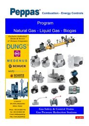
Dimensions [mm]<br />
A 40<br />
26<br />
137<br />
B 170<br />
81,5<br />
111,5 42 57,5<br />
A = Space requirement for opening the cover of pressure switch<br />
B = Space requirement for exchanging the solenoid<br />
Type<br />
Rp<br />
Opening<br />
time<br />
Weight<br />
[kg]<br />
<strong>MB</strong>-D <strong>403</strong> <strong>B01</strong><br />
<strong>MB</strong>-D<strong>LE</strong> <strong>403</strong> <strong>B01</strong><br />
<strong>MB</strong>-D <strong>053</strong> <strong>B01</strong><br />
<strong>MB</strong>-D<strong>LE</strong> <strong>053</strong> <strong>B01</strong><br />
Rp 1/2<br />
Rp 1/2<br />
Rp 1/2<br />
Rp 1/2<br />
< 1 s<br />
< 20 s<br />
< 1 s<br />
< 20 s<br />
1.4<br />
1.5<br />
1.4<br />
1.5<br />
Rating / power consumption<br />
[VA] 230 V AC; +20°C<br />
<strong>MB</strong>…<strong>403</strong> <strong>B01</strong> S 20<br />
<strong>MB</strong>…<strong>403</strong> <strong>B01</strong> S 22<br />
<strong>MB</strong>…<strong>053</strong> <strong>B01</strong> S 20<br />
<strong>MB</strong>…<strong>053</strong> <strong>B01</strong> S 22<br />
24<br />
36<br />
24<br />
36<br />
5 … 6
GasMultiBloc<br />
Combined regulator and<br />
safety shut-off valves<br />
Single-stage function<br />
<strong>MB</strong>-D(<strong>LE</strong>) <strong>403</strong> <strong>B01</strong><br />
<strong>MB</strong>-D(<strong>LE</strong>) <strong>053</strong> <strong>B01</strong><br />
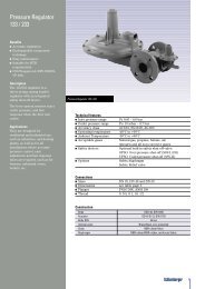
Volumetric flow pressure loss characteristics in regulated state with microfilter<br />
100<br />
80<br />
p Br<br />
= 3 mbar<br />
∆p [mbar]<br />
60<br />
50<br />
40<br />
30<br />
20<br />
10<br />
8<br />
6<br />
5<br />
4<br />
3<br />
V min. <strong>MB</strong>-D(<strong>LE</strong>) <strong>053</strong>/<strong>403</strong><br />
Recommended<br />
operating range<br />
<strong>MB</strong>-D(<strong>LE</strong>) <strong>053</strong>/<strong>403</strong> Rp 3/8 - Rp 3/8<br />
<strong>MB</strong>-D(<strong>LE</strong>) <strong>053</strong>/<strong>403</strong> Rp 1/2 - Rp 1/2<br />
2<br />
1<br />
Basis + 15° C, 1013 mbar, trocken<br />
Based on + 15° C, 1013 mbar, dry<br />
Base + 15° C, 1013 mbar, sec<br />
Base + 15° C, 1013 mbar, secco<br />
0,1 0,2 0,3 0,4 0,5 0,6 0,8<br />
1 2 3 4 5 6 7 8 910 20 30 40 60 80 100 200<br />
Vn ° [m 3 /h] Luft / Air / Aria dv = 1,00<br />
0,2 0,3 0,4 0,50,6 0,8<br />
1 2 3 4 5 6 7 8 910 20 30 40 60 80 100 200<br />
Vn ° [m 3 /h] Erdgas/Natural gas/Gaz Naturel/Gas metano dv = 0,65<br />
f =<br />
Dichte Luft<br />
Spec. weight air<br />
poids spécifique de l'air<br />
peso specifico aria<br />
Dichte des verwendeten Gases<br />
Spec. weight of gas used<br />
poids spécifique du gaz utilisé<br />
peso specifico del gas utilizzato<br />
Gas type<br />
Nat. gas<br />
City gas<br />
LPG<br />
Air<br />
Density<br />
[kg/m 3 ]<br />
0.81<br />
0.58<br />
2.08<br />
1.24<br />
dv<br />
0.65<br />
0.47<br />
1.67<br />
1.00<br />
f<br />
1.24<br />
1.46<br />
0.77<br />
1.00<br />
V<br />
°<br />
verwendetes Gas/gas used/ gaz utilisé/gas utilizzato<br />
=<br />
° V Luft/air/air/aria<br />
x f<br />
We reserve the right to make any changes in the interest of technical progress.<br />
Head Offices and Factory<br />
Karl Dungs GmbH & Co. KG<br />
Siemensstraße 6-10<br />
D-73660 Urbach, Germany<br />
Telephone +49 (0)7181-804-0<br />
Fax +49 (0)7181-804-166<br />
Postal address<br />
Karl Dungs GmbH & Co. KG<br />
Postfach 12 29<br />
D-73602 Schorndorf, Germany<br />
e-mail info@dungs.com<br />
Internet www.dungs.com<br />
6 … 6