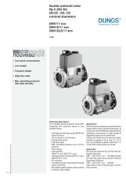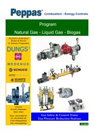
403 B01 MB-D(LE) 053 B01 - Peppas Ltd Combustion - energy ...
403 B01 MB-D(LE) 053 B01 - Peppas Ltd Combustion - energy ...
403 B01 MB-D(LE) 053 B01 - Peppas Ltd Combustion - energy ...

You also want an ePaper? Increase the reach of your titles
YUMPU automatically turns print PDFs into web optimized ePapers that Google loves.
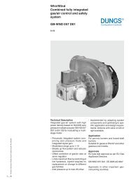
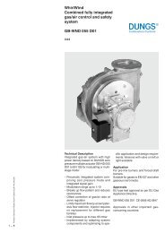
Functional description of gas flow<br />
1. When the valves V1 and V2 are<br />
closed, chamber A is under inlet<br />
pressure.<br />
2. A hole D in the filter housing connects<br />
min. pressure switch with<br />
chamber A. If the inlet pressure<br />
applied to the pressure switch exceeds<br />
the incoming reference value,<br />
it switches through to the automatic<br />
burner control.<br />
3. After release by the automatic burner<br />
control, valves V1 and V2 open.<br />
The gas flows through chambers A,<br />
B and C of the GasMultiBloc.<br />
Operating method of valve-regulator<br />
combination on valve V1<br />
A regulator, compensating for residual<br />
pressure is integrated in valve V1 (pressure<br />
regulating part). Armature 7 is not<br />
connected to valve plate unit 3. When<br />
it opens, armature 7 pretensions compression<br />
spring (V1) 5 and releases<br />
the valve plate unit. When the valve<br />
closes, the armature acts directly on<br />
the valve plate unit. The output pressure<br />
upstream of valve V2 is defined<br />
by pretensioning regulating spring 8<br />
(tension spring) via setting screw 16.<br />
The output pressure acts via opening E<br />
on the working diaphragm of regulator<br />
part 1. In regulated state, setting spring<br />
inlet pressure and pressure of working<br />
diaphragm are in force equilibrium.<br />
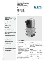
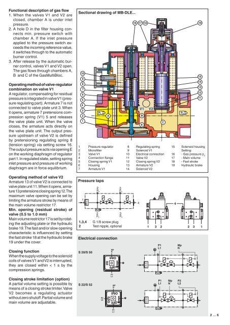
Sectional drawing of <strong>MB</strong>-D<strong>LE</strong>...<br />
10<br />
9<br />
8<br />
7<br />
6<br />
5<br />
4<br />
3<br />
2<br />
1<br />
1 Pressure regulator<br />
2 Microfilter<br />
3 Valve V1<br />
4 Connection flange<br />
5 Closing spring V1<br />
6 Housing<br />
7 Armature V1<br />
16<br />
17<br />
V1<br />
V2<br />
p 1 p 2<br />
A<br />
B<br />
E<br />
18 19<br />
C<br />
8 Regulating spring<br />
9 Solenoid V1<br />
10 Electrical connection<br />
11 Valve V2<br />
12 Closing spring V2<br />
13 Armature V2<br />
14 Solenoid V2<br />
15<br />
14<br />
13<br />
12<br />
11<br />
15 Solenoid housing<br />
Setting:<br />
16 - Gas pressure p a<br />
17 - Main volume<br />
18 - Fast stroke<br />
19 Hydraulic brake<br />
Operating method of valve V2<br />
Armature 13 of valve V2 is connected to<br />
valve plate unit 11. When it opens, armature<br />
13 pretensions closing spring 12. The<br />
maximum valve opening can be set by<br />
limiting the armature stroke by means of<br />
the main volume restrictor 17.<br />
Min. opening (residual stroke) of<br />
valve (0.5 to 1.0 mm)<br />
Main volume restrictor 17 is set by rotating<br />
the adjusting plate or the hydraulic<br />
brake 19. The fast and/or slow opening<br />
characteristic is influenced by setting<br />
the fast stroke 18 at the hydraulic brake<br />
19 under the cover.<br />
Closing function<br />
When the supply voltage to the solenoid<br />
coils of valves V1 and V2 is interrupted,<br />
they are closed within < 1 s by the<br />
compression springs.<br />
Closing stroke limitation (option)<br />
A partial volume setting is possible by<br />
means of a closing stroke limiter. Valve<br />
V2 becomes a regulating actuator<br />
without zero shutoff. Partial volume and<br />
main volume are adjustable.<br />
Pressure taps<br />
1<br />
1<br />
2<br />
p e<br />
1,3,4 G 1/8 P1 screw plug Mp<br />
2 Test L1nipple, optional N<br />
Electrical connection<br />
S 20/S 50<br />
S 22/S 52<br />
2<br />
p e<br />
P1<br />
L1<br />
P2<br />
L2<br />
Mp<br />
N<br />
3<br />
MP<br />
N<br />
P1<br />
L1<br />
1<br />
2<br />
MP<br />
N<br />
P2<br />
L2<br />
1<br />
2<br />
3<br />
pa<br />
3<br />
pa<br />
4<br />
4<br />
1 3 P12 Mp 2 3 1<br />
L1<br />
N<br />
P1<br />
L1<br />
P1<br />
L1<br />
P1<br />
L1<br />
Mp<br />
N<br />
Mp<br />
N<br />
Mp<br />
N<br />
P2<br />
L2<br />
P2<br />
L2<br />
P1<br />
L1<br />
2 … 6