Pressure Regulator 133 / 233 - Peppas Ltd Combustion - energy ...
Pressure Regulator 133 / 233 - Peppas Ltd Combustion - energy ...
Pressure Regulator 133 / 233 - Peppas Ltd Combustion - energy ...

You also want an ePaper? Increase the reach of your titles
YUMPU automatically turns print PDFs into web optimized ePapers that Google loves.
<strong>Pressure</strong> <strong>Regulator</strong><br />
<strong>133</strong> / <strong>233</strong><br />
Benefits<br />
■ Accurate regulation<br />
■ Exchangeable component<br />
technique<br />
■ Easy maintenance<br />
■ Suitable for HTB<br />
requirements<br />
■ DVGW-approval (DIN 3380/81,<br />
VP 200).<br />
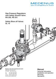
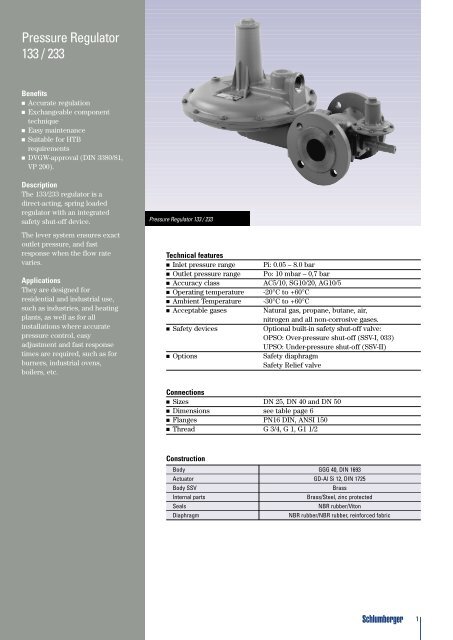
Description<br />
The <strong>133</strong>/<strong>233</strong> regulator is a<br />
direct-acting, spring loaded<br />
regulator with an integrated<br />
safety shut-off device.<br />
The lever system ensures exact<br />
outlet pressure, and fast<br />
response when the flow rate<br />
varies.<br />
Applications<br />
They are designed for<br />
residential and industrial use,<br />
such as industries, and heating<br />
plants, as well as for all<br />
installations where accurate<br />
pressure control, easy<br />
adjustment and fast response<br />
times are required, such as for<br />
burners, industrial ovens,<br />
boilers, etc.<br />
<strong>Pressure</strong> <strong>Regulator</strong> <strong>133</strong> / <strong>233</strong><br />
Technical features<br />
■ Inlet pressure range<br />
■ Outlet pressure range<br />
■ Accuracy class<br />
■ Operating temperature<br />
■ Ambient Temperature<br />
■ Acceptable gases<br />
■ Safety devices<br />
■ Options<br />
Pi: 0.05 – 8.0 bar<br />
Po: 10 mbar – 0,7 bar<br />
AC5/10, SG10/20, AG10/5<br />
-20°C to +60°C<br />
-30°C to +60°C<br />
Natural gas, propane, butane, air,<br />
nitrogen and all non-corrosive gases.<br />
Optional built-in safety shut-off valve:<br />
OPSO: Over-pressure shut-off (SSV-I, 033)<br />
UPSO: Under-pressure shut-off (SSV-II)<br />
Safety diaphragm<br />
Safety Relief valve<br />
Connections<br />
■ Sizes DN 25, DN 40 and DN 50<br />
■ Dimensions see table page 6<br />
■ Flanges PN16 DIN, ANSI 150<br />
■ Thread G 3/4, G 1, G1 1/2<br />
Construction<br />
Body GGG 40, DIN 1693<br />
Actuator GD-Al Si 12, DIN 1725<br />
Body SSV<br />
Brass<br />
Internal parts<br />
Brass/Steel, zinc protected<br />
Seals<br />
NBR rubber/Viton<br />
Diaphragm<br />
NBR rubber/NBR rubber, reinforced fabric<br />
1
<strong>Pressure</strong> <strong>Regulator</strong><br />
<strong>133</strong> / <strong>233</strong><br />
The <strong>133</strong>/<strong>233</strong> regulators are<br />
direct-acting, spring loaded<br />
regulators, which can be used for all<br />
non-aggressive gases. The required<br />
outlet pressure can be easily set to<br />
another command range by<br />
adjusting the command variable, or<br />
by exchanging the spring. Due to<br />
their spring principle, these<br />
regulators operate independently of<br />
their positions. They offer various<br />
installation possibilities as a result<br />
of flange connections between the<br />
actuator body and the regulating<br />
unit and, flange connections<br />
between the actuator body and the<br />
SSV switching device. The nozzle,<br />
regulating unit, and SSV switching<br />
device, can be exchanged without<br />
removing the actuator body from the<br />
regulated member.<br />
The safety shut-off valve is equipped<br />
with a thermally working element.<br />
All models with a leaking gas<br />
blow-off valve (SRV) have a fixed<br />
blow-off pressure 1 ).<br />
The blow-off pressure is,<br />
independently of the setting of the<br />
outlet pressure, approximately<br />
30 mbar above Pa.<br />
A ventilation/blow-off line has to be<br />
connected to the ventilation<br />
connection of the regulator. The<br />
models with safety diaphragms are<br />
not equipped with the SBV and the<br />
ventilation/blow-off line. If the<br />
working diaphragm is damaged, the<br />
safety diaphragm prevents gas from<br />
leaking in unacceptable amounts.<br />
1) See accuracy class SRV page 8<br />
ventilation connection<br />
with sieve<br />
design with<br />
integrated safety<br />
diaphragm<br />
feeler (1)<br />
(diaphragm)<br />
ventilation<br />
connection<br />
desired-value setting<br />
loaded spring<br />
flange connection<br />
actuator body<br />
actuator (4,7)<br />
(exchangeable nozzles)<br />
valve disk<br />
loaded spring (10)<br />
measuring unit<br />
with lever system (34)<br />
(5)<br />
valve rod<br />
reset with cap<br />
(26,35)<br />
design with<br />
leaking-gas<br />
blow-off valve SRV<br />
(8)<br />
(6)<br />
diaphragm compartment<br />
regulating unit body<br />
lever system (3)<br />
with actuator<br />
closing spring (14)<br />
SSV with<br />
thermal shutoff<br />
flange connection<br />
2
<strong>Pressure</strong> <strong>Regulator</strong><br />
<strong>133</strong> / <strong>233</strong><br />
Technical Data and Type Designation<br />
Type <strong>133</strong>, Pi 0.05 - 4.0 bar<br />
■ <strong>Pressure</strong> rate<br />
Inlet pressure<br />
■ PN 1<br />
0.05 - 1.0 bar<br />
■ PN 4<br />
0.35 - 4.0 bar<br />
■ Outlet pressure<br />
8 - 420 mbar<br />
■ Flow rate, up to<br />
65 m 3 /h Natural gas<br />
■ Working temperature -20° bis +60°C<br />
■ Connection / Size see page 5<br />
Type <strong>233</strong>, Pi 0.05 - 4.0 bar<br />
■ <strong>Pressure</strong> rate<br />
Inlet pressure<br />
■ PN 1<br />
0.05 - 1.0 bar<br />
■ PN 4<br />
0.37 - 4.0 bar<br />
■ Outlet pressure<br />
8 - 700 mbar<br />
■ Flow rate, up to<br />
400 m 3 /h Natural gas<br />
■ Working temperature -20° bis +60°C<br />
■ Connection / Size see page 5<br />
Designation of regulator <strong>133</strong> and <strong>233</strong> 1<br />
for Pe 0.1 - 4.0 2 bar<br />
approved according VP 200,<br />
DIN 3380 / 81 with DVGW-Reg. No.,<br />
with “t” (HTB):<br />
- 31 without safety devices<br />
- 32 with SRV<br />
- 61 SSV Pso ≥ 400 mbar<br />
- 62 SSV Pso ≥ 400 mbar and SRV<br />
- 64 SSV Pso and Psu<br />
- 66 SSV Pso and Psu and SRV<br />
- 71 SSV Pso ≤ 450 mbar<br />
- 72 SSV Pso ≤ 450 mbar and SRV<br />
- 77 SSV Pso ≤ 450 mbar, SRV and<br />
gas loss protection, PN 1 (only <strong>133</strong>)<br />
- 630 SSV Pso ≥ 400 mbar and safety<br />
diaphragm, PN 1<br />
(<strong>133</strong> and <strong>233</strong>-8”/-12”)<br />
- 650 SSV Pso and Psu, as well as<br />
safety diaphragm, PN 1<br />
(<strong>133</strong> and <strong>233</strong>-8”/-12”)<br />
- 730 SSV Pso ≤ 450 mbar and safety<br />
diaphragm, PN 1<br />
(<strong>133</strong> and <strong>233</strong>-8”/-12”)<br />
- 770 SSV Pso ≤ 450 mbar, gas loss<br />
protection and safety diaphragm,<br />
PN 1 (only regulator <strong>133</strong>)<br />
(1) select the diaphragm housing -8" or -12"<br />
(2) note the max. orifice-Ø<br />
Type <strong>133</strong>, Pi > 4.0 - 6.0 bar<br />
■ <strong>Pressure</strong> rate<br />
Inlet pressure<br />
■ PN 6<br />
0.35 - 6.0 bar<br />
■ Max. orifice-Ø<br />
3/16” (4.7mm)<br />
■ Outlet pressure<br />
20 - 420 mbar<br />
■ Flow rate, up to<br />
65 m 3 /h Natural gas<br />
■ Working temperature -20° bis +60°C<br />
■ External impulse<br />
■ Connection / Size see page 5<br />
3
<strong>Pressure</strong> <strong>Regulator</strong><br />
<strong>133</strong> / <strong>233</strong><br />
Type <strong>233</strong>, Pi > 4.0 - 6.0 bar<br />
■ <strong>Pressure</strong> rate<br />
Inlet pressure<br />
■ PN 6<br />
0.35 - 6.0 bar<br />
■ Max. orifice-Ø<br />
3/8” (10mm)<br />
■ Outlet pressure<br />
20 - 700 mbar<br />
■ Flow rate, up to<br />
400 m 3 /h Natural gas<br />
■ Working temperature -20° bis +60°C<br />
■ External impulse<br />
■ Connection / Size see page 5<br />
Designation of regulator <strong>133</strong> and <strong>233</strong> 1<br />
for Pe >4.0 - 6.0 2 bar<br />
approved according DIN 3380 / 81<br />
with DVGW-Reg. No., without “t”:<br />
- 32 with SRV<br />
- 66 SSV pso and psu, as well as SRV<br />
(1) select the diaphragm housing -8" or -12"<br />
(2) note the max. orifice-Ø<br />
Designation of regulator <strong>133</strong> and <strong>233</strong> 1<br />
for Pi up to 8.0 2 bar<br />
without DVGW-Reg N°.<br />
- 31 without safety devices<br />
- 32 with SRV<br />
- 34 with gas loss protection<br />
- 36 with gas loss protection<br />
and SRV<br />
- 61 SSV Pso<br />
- 62 SSV Pso and SRV<br />
- 64 SSV Pso and Psu<br />
- 66 SSV Pso and Psu and SRV<br />
Type Designation<br />
Example:<br />
<strong>Regulator</strong> type <strong>233</strong>, pressure stage<br />
PN 4, 12” diaphragm housing, SSV<br />
for upper shut off ≤ 450 mbar, with<br />
safety relief valve (SRV):<br />
Type <strong>233</strong> – 12 – 4 – 72<br />
Type 3<br />
Diaphragm housing 2<br />
<strong>Pressure</strong> rate 1<br />
Safety shut-off valve (see table)<br />
(1) no digit for pressure rate PN 1<br />
(2) no diaphragm housing size<br />
for type <strong>133</strong><br />
(3) Type <strong>133</strong> single pipe marked <strong>133</strong>-E<br />
Construction<br />
Body GGG 40, DIN 1693<br />
Diaphragm housing GD-Al Si 12 DIN 1725<br />
SSV-Body<br />
Brass, hot pressed<br />
Orifice<br />
Brass<br />
Diaphragm<br />
NBR/NBR reinforced<br />
O-rings<br />
NBR/Viton<br />
Valve disk regulator<br />
Aluminium/NBR<br />
Valve disk SSV<br />
Brass/NBR<br />
4
<strong>Pressure</strong> <strong>Regulator</strong><br />
<strong>133</strong> / <strong>233</strong> <strong>Regulator</strong> variants<br />
Type <strong>133</strong> DN 25, PN 16<br />
ANSI 150<br />
Female<br />
thread<br />
Male<br />
thread<br />
DN 25,<br />
PN 16<br />
DN 25,<br />
<strong>133</strong>-E<br />
SSV<br />
Type <strong>233</strong>-12<br />
G 3/4”, G1”<br />
3/4”-, 1”-NPT<br />
3/4”-, 1”-BSPT<br />
G1 1/2”<br />
(140 mm<br />
length)<br />
G1 1/2”<br />
(160 mm<br />
length)<br />
Type <strong>233</strong>-8<br />
DN 50, PN 16<br />
ANSI 150<br />
DN 40, PN 16<br />
ANSI 150<br />
Female thread<br />
G1 1/2”, 1 1/2” NPT<br />
1 1/2”-BSPT<br />
SSV<br />
Installation<br />
Please indicate desired installating<br />
position when you order. If not<br />
otherwise stated, the regulators are<br />
assembled and adjusted for normal<br />
installation (position 2):<br />
<strong>Regulator</strong> <strong>133</strong>-vent pointing outward,<br />
<strong>Regulator</strong> <strong>233</strong>-vent pointing inward.<br />
Pos. 1<br />
Pos. 3* <strong>Regulator</strong> <strong>233</strong>-vent Pos. 5<br />
pointing outward<br />
Pos. 2 Pos. 4* <strong>Regulator</strong> <strong>233</strong>-vent Pos. 6<br />
pointing outward<br />
Pos. 7 Pos. 8 Pos. 9 Pos. 10<br />
*) Pos. 3 and 4: Not to use for <strong>233</strong>-8 (-12) -71/ -72/ -730<br />
5
<strong>Pressure</strong> <strong>Regulator</strong><br />
<strong>133</strong> / <strong>233</strong><br />
Dimensions<br />
J<br />
Model Thread Flange A B C’ C D E F G H J K Weight in kg<br />
Type Size Ventilation (approx.)<br />
(1) (2) Connection (1) (2)<br />
<strong>133</strong>- 3/4“/1” DN 25 190 155 100 160 170 100 100 75 120 Rp 3/4 74 4 6<br />
<strong>233</strong>-12 1 1/2“ DN 40 350 250 150 200 265 155 115 75 120 Rp 1 110 11 15<br />
<strong>233</strong>-12 - DN 50 350 250 - 200 265 155 115 75 120 Rp 1 110 - 16<br />
<strong>233</strong>-8 1 1/2“ DN 40 260 250 150 200 220 125 115 75 120 Rp 1 105 9 13<br />
<strong>233</strong>-8 - DN 50 260 250 - 200 220 125 115 75 120 Rp 1 105 - 14<br />
J<br />
Dimension, Type <strong>133</strong>-E<br />
R L N<br />
Rp 1 110 41<br />
Rp 1-1/2” 140 50<br />
6
<strong>Pressure</strong> <strong>Regulator</strong><br />
<strong>133</strong> / <strong>233</strong><br />
Command and adjustable range<br />
Command ranges for <strong>Pressure</strong> Springs<br />
<strong>Regulator</strong> Type Command range Part No. Colour marking<br />
9 – 15 mbar 955-200-08 red<br />
<strong>133</strong> 14 – 20 mbar 955-200-09 blue<br />
with gas loss 18 – 26 mbar 955-201-06 silver<br />
protection 24 – 40 mbar 955-202-98 yellow<br />
38 – 53 mbar 955-200-11 orange<br />
8 – 16 mbar 955-200-08 red<br />
12 – 20 mbar 955-200-09 blue<br />
<strong>133</strong><br />
15 – 35 mbar 955-200-10 green<br />
30 – 70 mbar 955-200-11 orange<br />
50 – 140 mbar 955-200-12 black-white<br />
100 – 210 mbar 955-200-83 silver<br />
<strong>133</strong> HP 140 – 420 mbar 955-200-84 black<br />
8 – 16 mbar 955-200-13 red<br />
12 – 20 mbar 955-200-14 blue<br />
<strong>233</strong>-12<br />
15 – 35 mbar 955-200-15 green<br />
30 – 70 mbar 955-200-16 orange<br />
70 – 140 mbar 955-200-17 black<br />
100 – 210 mbar 955-200-18 metal blank<br />
30 – 70 mbar 955-200-15 green<br />
<strong>233</strong>-8<br />
70 – 140 mbar 955-200-16 orange<br />
140 – 300 mbar 955-200-17 black<br />
210 – 450 mbar 955-200-18 metal blank<br />
<strong>233</strong>-8 HP<br />
420 – 700 mbar 955-200-69 silver<br />
955-200-18 metal blank<br />
Adjustable ranges for SSV, Type 033 for upper shut-off<br />
Shut-off Adjustable range Part No. Colour marking<br />
Upper 40 – 70 mbar 955-200-22 red<br />
(overpressure) 50 – 150 mbar 955-200-23 blue<br />
Pso 140 – 450 mbar 955-200-24 green<br />
Adjustable ranges SSV -I,-II for upper and lower shut-off<br />
Shut-off Adjustable range Part No. Colour marking<br />
Upper 20 – 60 mbar 955-200-22 red<br />
(overpressure) 50 – 120 mbar 955-200-23 blue<br />
100 – 400 mbar 955-200-24 green<br />
Pso<br />
300 – 600 mbar 955-200-52 brown<br />
400 – 1000 mbar 955-202-42 silver<br />
Lower 8 – 50 mbar 955-200-32 red<br />
(underpressure) Psu<br />
7
<strong>Pressure</strong> <strong>Regulator</strong><br />
<strong>133</strong> / <strong>233</strong><br />
Accuracy class and closing group<br />
regulator (AC, SG):<br />
Outlet pressure po:<br />
8 mbar - 20 mbar:<br />
AC 20 / SG 30<br />
>20 mbar - 50 mbar:<br />
AC 10 / SG 20<br />
> 50 mbar - 420 mbar:<br />
AC 5 / SG 10<br />
Response closing group SSV:<br />
Upper response pressure Pso,<br />
40 –1000 mbar:<br />
AG 10<br />
Lower response pressure Psu,<br />
8 – 20 mbar:<br />
AG 30<br />
>20 – 50 mbar:<br />
AG 10<br />
Accuracy class SRV:<br />
(Po + approx. 30 mbar) ± 10%<br />
Ventilation:<br />
Gas pressure regulators without a<br />
safety diaphragm, and gas pressure<br />
regulators with an integrated safety<br />
reliev valve (SRV), require<br />
ventilation and blow-off lines<br />
respectively.<br />
The minimum diameters stipulated<br />
by the DIN 3380 standards are DN 15.<br />
In order to ensure disturbance-free<br />
regulation and a sufficiently quick<br />
response for load changes, the<br />
following nominal widths and<br />
installation lengths have to be<br />
observed:<br />
up to 3 m ventilation line: DN 20<br />
up to 5 m ventilation line: DN 25<br />
For longer lengths, at least DN 40 is<br />
recommended.<br />
<strong>Pressure</strong> difference minimal,<br />
between<br />
outlet pressure Po and SSV shut-off:<br />
SSV 033:<br />
20 mbar between Po and Pso<br />
SSV II, lower:<br />
14 mbar between Po and Psu<br />
SSV II, upper:<br />
20 mbar between Po and Pso<br />
<strong>Regulator</strong> Type <strong>133</strong>-E, Body DN 25,<br />
Pe max 1.0 bar<br />
Flow rate in m 3 /h natural gas in<br />
standard state (ρn = 0.78 kg/m 3 )<br />
Adjustable Data<br />
Inlet<br />
Outlet <strong>Pressure</strong> <strong>Pressure</strong> Orifice Inserts<br />
Po (mbar) Pi (bar)<br />
Spring range / 12.5 mm 10 mm 8 mm 6.3 mm 4.7 mm 3 mm<br />
No. / colour (1/2”) (3/8”) (5/16”) (1/4”) (3/16”) (1/8”)<br />
Po = 20 mbar 0.1 16 15 12 11 7 3<br />
Command Range 0.3 27 26 18 14 12 6<br />
15 – 35 mbar 0.5 32 28 19 17 15 8<br />
955-200-10 green 1.0 38 37 20 20 19 11<br />
Po = 50 mbar 0.1 - - - - - -<br />
Command Range 0.3 20 16 12 10 7 5<br />
30 – 70 mbar 0.5 24 20 14 12 10 6<br />
955-200-11 orange 1.0 29 26 17 16 14 10<br />
Po = 100 mbar 0.1 - - - - - -<br />
Command Range 0.3 21 18 12 10 9 4<br />
35 – 140 mbar 0.5 28 23 16 12 10 6<br />
955-200-12 blk-white 1.0 40 38 23 19 16 10<br />
8
<strong>Pressure</strong> <strong>Regulator</strong><br />
<strong>133</strong> / <strong>233</strong><br />
<strong>Regulator</strong> Type <strong>133</strong>-77 and -770<br />
(with gas loss protection),<br />
Body DN 25, Pe max 1.0 bar<br />
Flow rate in m 3 /h natural gas in<br />
standard state (ρn = 0.78 kg/m 3 )<br />
Adjustable Data<br />
Outlet <strong>Pressure</strong> Inlet<br />
Orifice<br />
Po (mbar) <strong>Pressure</strong><br />
∅ 12.5 mm<br />
Spring range / Pi (bar)<br />
No. / colour<br />
Po = 20 mbar 0.1 13<br />
Command Range 0.3 20<br />
18 – 26 mbar 0.5 25<br />
955-2001-06 1.0 32<br />
Po = 50 mbar 0.15 14<br />
Command Range 0.3 22<br />
38 – 53 mbar 0.5 27<br />
955-200-11 1.0 34<br />
<strong>Regulator</strong> Type <strong>133</strong>,<br />
Actuator Body DN 25<br />
Flow rate in m 3 /h natural gas in<br />
standard state (ρn = 0.78 kg/m 3 )<br />
(see footnotes 1. and 2.)<br />
Adjustable Data<br />
Inlet<br />
Outlet <strong>Pressure</strong> <strong>Pressure</strong> 1 Orifice Inserts<br />
Po (mbar) Pi (bar)<br />
Spring range / 12.5 mm 10 mm 8 mm 6.3 mm 4.7 mm 3 mm<br />
No. / colour (1/2”) (3/8”) (5/16”) (1/4”) (3/16”) (1/8”)<br />
0.1 24 17 16 9 - -<br />
0.3 40 36 29 22 13 6<br />
Po = 20 mbar 0.5 48 46 40 30 17 8<br />
Command Range 1.0 61 56 53 41 25 12<br />
15 – 35 mbar 1.5 - 63 61 56 33 14<br />
<strong>Pressure</strong> Spring 2.0 - 64 63 57 38 18<br />
955-200-10 3.0 - - - 59 51 24<br />
green 4.0 - - - 64 52 31<br />
5.0 - - - - 53 35<br />
6.0 - - - - 54 40<br />
8.0 - - - - 60 50<br />
0.1 14 13 11 - - -<br />
0.3 31 29 22 16 12 4<br />
Po = 50 mbar 0.5 44 42 37 24 15 8<br />
Command Range 1.0 58 52 46 40 24 11<br />
30 – 70 mbar 1.5 - 59 57 54 30 14<br />
<strong>Pressure</strong> Spring 2.0 - 61 60 56 35 16<br />
955-200-11 3.0 - - - 60 48 22<br />
orange 4.0 - - - 65 53 27<br />
5.0 - - - - 54 30<br />
6.0 - - - - 56 36<br />
8.0 - - - - 66 50<br />
0.2 22 18 14 12 8 3<br />
0.3 33 28 18 16 11 4<br />
Po = 100 mbar 0.5 50 35 28 24 12 8<br />
Command Range 1.0 60 52 48 39 23 12<br />
50 – 140 mbar 1.5 - 58 56 52 29 13<br />
<strong>Pressure</strong> Spring 2.0 - 60 59 55 34 16<br />
955-200-12 3.0 - - - 60 48 21<br />
black-white 4.0 - - - 63 52 25<br />
5.0 - - - - 60 31<br />
6.0 - - - - 65 35<br />
8.0 - - - - 70 50<br />
(1) With Pi > 4.0 bar, external impulse is required.<br />
(2) The volumes below the lines are not regulated with the accuracy indicated.<br />
9
<strong>Pressure</strong> <strong>Regulator</strong><br />
<strong>133</strong> / <strong>233</strong><br />
<strong>Regulator</strong> Type <strong>133</strong>,<br />
Actuator Body DN 25<br />
Adjustable Data<br />
Inlet<br />
Flow rate in m 3 /h natural gas in<br />
standard state (ρn = 0.78 kg/m 3 )<br />
(see footnotes 1. and 2.)<br />
Outlet <strong>Pressure</strong> <strong>Pressure</strong> 1 Orifice Inserts<br />
Po (mbar) Pi (bar)<br />
Spring range / 12.5 mm 10 mm 8 mm 6.3 mm 4.7 mm 3 mm<br />
No. / colour (1/2”) (3/8”) (5/16”) (1/4”) (3/16”) (1/8”)<br />
0.1 - - - - - -<br />
0.3 18 15 12 10 7 3<br />
Po = 140 mbar 0.5 25 21 17 14 10 6<br />
Command Range 1.0 44 36 29 22 17 10<br />
100 – 210 mbar 1.5 - 46 38 28 24 13<br />
<strong>Pressure</strong> Spring 2.0 - 53 43 35 29 16<br />
955-200-83 3.0 - - 56 47 39 22<br />
silver 4.0 - - - 59 49 26<br />
5.0 - - - - 55 31<br />
6.0 - - - - 65 35<br />
8.0 - - - - 79 46<br />
0.5 18 15 11 8 6 -<br />
1.0 35 29 23 16 13 9<br />
Po = 300 mbar 1.5 - 38 33 25 18 12<br />
Command Range 2.0 - 46 40 33 25 15<br />
140 – 420 mbar 3.0 - - 53 43 38 21<br />
<strong>Pressure</strong> Spring 4.0 - - 66 51 46 26<br />
955-200-84 5.0 - - - - 55 31<br />
black 6.0 - - - - 65 35<br />
8.0 - - - - 79 42<br />
0.7 26 22 17 12 10 6<br />
1.0 33 28 21 17 12 8<br />
Po = 400 mbar 1.5 - 37 31 26 16 10<br />
Command Range 2.0 - 44 38 31 23 12<br />
140 – 420 mbar 3.0 - - 50 41 36 18<br />
<strong>Pressure</strong> Spring 4.0 - - 64 49 44 24<br />
955-200-84 5.0 - - - - 53 29<br />
black 6.0 - - - - 63 33<br />
8.0 - - - - 77 40<br />
(1) With Pi > 4.0 bar, external impulse is required.<br />
(2) The volumes below the lines are not regulated with the accuracy indicated.<br />
10
<strong>Pressure</strong> <strong>Regulator</strong><br />
<strong>133</strong> / <strong>233</strong><br />
<strong>Regulator</strong> Type <strong>233</strong>-12,<br />
Actuator Body DN 40<br />
Adjustable Data<br />
Inlet<br />
Flow rate in m 3 /h natural gas in<br />
standard state (ρn = 0.78 kg/m 3<br />
(see footnotes 1. and 2.)<br />
Outlet <strong>Pressure</strong> <strong>Pressure</strong> 1 Orifice Inserts / Valve Disk Angle<br />
Po (mbar) Pi (bar)<br />
Spring range / 25 mm (1”) 20 mm (3/4”) 12.5 mm (1/2”) 10 mm (3/8”) 6.3 mm (1/4”)<br />
No. / colour 30° 10° 10° 10° 10°<br />
0.1 75 58 40 24 12<br />
0.3 142 114 82 48 23<br />
0.5 188 149 110 64 32<br />
Po = 20 mbar 1.0 250 208 158 98 47<br />
Command Range 1.5 280 241 195 125 57<br />
15 – 35 mbar 2.0 - 260 215 147 68<br />
<strong>Pressure</strong> Spring 3.0 - 300 266 190 92<br />
955-200-15 4.0 - 310 300 210 113<br />
green 5.0 - - 300 230 120<br />
6.0 - - 300 250 130<br />
8.0 - - - 250 160<br />
0.1 51 43 26 20 -<br />
0.3 125 95 62 43 21<br />
0.5 169 130 88 58 29<br />
Po = 50 mbar 1.0 250 190 140 95 46<br />
Command Range 1.5 286 228 180 120 57<br />
30 – 70 mbar 2.0 - 254 210 140 68<br />
<strong>Pressure</strong> Spring 3.0 - 295 250 190 90<br />
955-200-16 4.0 - 315 280 220 110<br />
orange 5.0 - - 300 230 122<br />
6.0 - - 300 250 130<br />
8.0 - - - 250 160<br />
0.2 73 52 38 25 15<br />
0.3 110 81 54 36 20<br />
0.5 160 119 79 53 30<br />
Po = 100 mbar 1.0 237 183 136 90 44<br />
Command Range 1.5 266 221 168 119 57<br />
70– 140 mbar 2.0 - 258 204 142 65<br />
<strong>Pressure</strong> Spring 3.0 - 290 248 191 87<br />
955-200-17 4.0 - 319 277 230 109<br />
black 5.0 - - 300 240 124<br />
6.0 - - 300 250 130<br />
8.0 - - - 250 160<br />
0.4 140 107 70 45 22<br />
0.5 175 134 90 56 27<br />
Po = 200 mbar 1.0 304 224 156 98 43<br />
Command Range 1.5 355 272 207 127 57<br />
100– 210 mbar 2.0 - 291 230 142 64<br />
<strong>Pressure</strong> Spring 3.0 - 350 287 190 86<br />
955-200-18 4.0 - 376 310 230 110<br />
silver 5.0 - - 320 250 125<br />
6.0 - - 330 260 130<br />
8.0 - - - 260 160<br />
(1) With Pi > 4.0 bar, external impulse is required.<br />
(2) The volumes below the lines are not regulated with the accuracy indicated.<br />
11
<strong>Pressure</strong> <strong>Regulator</strong><br />
<strong>133</strong> / <strong>233</strong><br />
<strong>Regulator</strong> Type <strong>233</strong>-8,<br />
Actuator Body DN 40<br />
Adjustable Data<br />
Inlet<br />
Flow rate in m 3 /h natural gas in<br />
standard state (ρn = 0.78 kg/m 3 )<br />
(see footnotes 1. and 2.)<br />
Outlet <strong>Pressure</strong> <strong>Pressure</strong> 1 Orifice Inserts / Valve Disk Angle<br />
Po (mbar) Pi (bar)<br />
Spring range / 25 mm (1”) 20 mm (3/4”) 12.5 mm (1/2”) 10 mm (3/8”) 6.3 mm (1/4”)<br />
No. / colour 30° 10° 10° 10° 10°<br />
0.2 75 56 30 19 14<br />
0.3 105 78 47 30 18<br />
0.5 142 115 68 46 26<br />
Po = 50 mbar 1.0 235 189 132 90 46<br />
Command Range 1.5 262 223 166 118 55<br />
30 – 70 mbar 2.0 - 255 200 147 68<br />
<strong>Pressure</strong> Spring 3.0 - - 243 190 90<br />
955-200-15 4.0 - - 278 232 112<br />
green 5.0 - - 293 254 126<br />
6.0 - - 304 270 138<br />
8.0 - - - - 170<br />
0.3 93 73 41 26 18<br />
0.5 136 106 65 42 26<br />
Po = 100 mbar 1.0 220 170 114 79 41<br />
Command Range 1.5 261 205 149 102 55<br />
70 – 140 mbar 2.0 - 236 180 126 66<br />
<strong>Pressure</strong> Spring 3.0 - - 231 186 87<br />
955-200-16 4.0 - - 263 225 109<br />
orange 5.0 - - 285 248 128<br />
6.0 - - 300 275 146<br />
8.0 - - - - 178<br />
0.4 124 96 63 42 23<br />
0.5 148 118 79 52 27<br />
Po = 200 mbar 1.0 260 198 127 90 46<br />
Command Range 1.5 298 252 152 117 58<br />
140– 300 mbar 2.0 - 296 190 143 70<br />
<strong>Pressure</strong> Spring 3.0 - - 266 197 89<br />
955-200-17 4.0 - - 300 240 112<br />
black 5.0 - - 312 256 131<br />
6.0 - - 324 279 146<br />
8.0 - - - - 178<br />
0.7 152 126 86 61 32<br />
Po = 400 mbar 1.0 220 175 118 80 46<br />
Command Range 1.5 277 214 142 107 54<br />
210– 450 mbar 2.0 - 256 172 130 66<br />
<strong>Pressure</strong> Spring 3.0 - - 223 167 86<br />
955-200-18 4.0 - - 241 176 108<br />
silver 5.0 - - 266 206 127<br />
6.0 - - 281 217 142<br />
8.0 - - - - 172<br />
(1) With Pi > 4.0 bar, external impulse is required.<br />
(2) The volumes below the lines are not regulated with the accuracy indicated.<br />
12
<strong>Pressure</strong> <strong>Regulator</strong><br />
<strong>133</strong> / <strong>233</strong><br />
<strong>Regulator</strong> Type <strong>233</strong>-12,<br />
Actuator Body DN 50<br />
Adjustable Data<br />
Inlet<br />
Flow rate in m 3 /h natural gas in<br />
standard state (ρn = 0.78 kg/m 3 )<br />
(see footnotes 1. and 2.)<br />
Outlet <strong>Pressure</strong> <strong>Pressure</strong> 1 Orifice Inserts / Valve Disk Angle<br />
Po (mbar) Pi (bar)<br />
Spring range / 25 mm (1”) 20 mm (3/4”) 20 mm (3/4”) 12.5 mm (1/2”) 10 mm (3/8”) 6.3 mm (1/4”)<br />
No. / colour 30° 30° 10° 10° 10° 10°<br />
0.1 97 74 66 41 25 12<br />
0.3 214 180 142 79 50 23<br />
0.5 288 250 187 119 69 30<br />
Po = 20 mbar 1.0 385 360 267 182 106 46<br />
Command Range 1.5 425 400 292 230 128 57<br />
15 – 35 mbar 2.0 - 410 317 255 153 68<br />
<strong>Pressure</strong> Spring 3.0 - - 362 324 205 86<br />
955-200-15 4.0 - - 394 340 240 105<br />
green 5.0 - - - 350 264 118<br />
6.0 - - - 362 288 130<br />
8.0 - - - - 305 150<br />
0.1 66 52 45 31 20 -<br />
0.3 165 130 110 65 43 22<br />
0.5 245 200 157 97 60 29<br />
Po = 50 mbar 1.0 387 320 240 163 98 45<br />
Command Range 1.5 421 390 287 219 127 55<br />
30 – 70 mbar 2.0 - 410 317 255 152 66<br />
<strong>Pressure</strong> Spring 3.0 - - 365 312 205 89<br />
955-200-16 4.0 - - 394 340 240 110<br />
orange 5.0 - - - 350 264 123<br />
6.0 - - - 362 288 140<br />
8.0 - - - - 305 160<br />
0.2 95 65 60 40 30 14<br />
0.3 160 117 105 65 44 21<br />
0.5 241 178 155 97 62 29<br />
Po = 100 mbar 1.0 380 307 260 162 98 45<br />
Command Range 1.5 446 379 326 216 126 57<br />
70– 140 mbar 2.0 - 410 376 255 153 69<br />
<strong>Pressure</strong> Spring 3.0 - - 420 320 205 91<br />
955-200-17 4.0 - - 430 375 240 110<br />
black 5.0 - - - 390 270 125<br />
6.0 - - - 405 300 140<br />
8.0 - - - - 310 160<br />
0.4 165 125 110 70 45 25<br />
0.5 204 150 <strong>133</strong> 83 55 30<br />
Po = 200 mbar 1.0 320 248 221 149 97 45<br />
Command Range 1.5 371 310 267 198 126 57<br />
100– 210 mbar 2.0 - 360 305 230 152 71<br />
<strong>Pressure</strong> Spring 3.0 - - 360 300 205 91<br />
955-200-18 4.0 - - 400 320 240 110<br />
silver 5.0 - - - 330 265 125<br />
6.0 - - - 350 300 140<br />
8.0 - - - - 310 160<br />
(1) With Pi > 4.0 bar, external impulse is required.<br />
(2) The volumes below the lines are not regulated with the accuracy indicated.<br />
13
<strong>Pressure</strong> <strong>Regulator</strong><br />
<strong>133</strong> / <strong>233</strong><br />
<strong>Regulator</strong> Type <strong>233</strong>-8,<br />
Actuator Body DN 50<br />
Adjustable Data<br />
Inlet<br />
Flow rate in m 3 /h natural gas in<br />
standard state (ρn = 0.78 kg/m 3<br />
(see footnotes 1. and 2.)<br />
Outlet <strong>Pressure</strong> <strong>Pressure</strong> 1 Orifice Inserts / Valve Disk Angle<br />
Po (mbar) Pi (bar)<br />
Spring range / 25 mm (1”) 20 mm (3/4”) 20 mm (3/4”) 12.5 mm (1/2”) 10 mm (3/8”) 6.3 mm (1/4”)<br />
No. / colour 30° 30° 10° 10° 10° 10°<br />
0.2 75 60 48 34 22 14<br />
0.3 122 83 71 52 33 20<br />
0.5 187 148 117 74 49 28<br />
Po = 50 mbar 1.0 321 266 208 151 104 45<br />
Command Range 1.5 352 320 240 190 129 55<br />
30 – 70 mbar 2.0 - 370 270 231 155 66<br />
<strong>Pressure</strong> Spring 3.0 - - - 300 208 94<br />
955-200-15 4.0 - - - 340 236 117<br />
green 5.0 - - - 349 259 130<br />
6.0 - - - 358 281 141<br />
8.0 - - - - - 168<br />
0.3 94 78 75 45 28 20<br />
0.5 137 116 108 70 42 28<br />
Po = 100 mbar 1.0 293 241 189 122 83 46<br />
Command Range 1.5 342 332 232 164 107 55<br />
70 – 140 mbar 2.0 - 401 270 208 134 66<br />
<strong>Pressure</strong> Spring 3.0 - - - 281 189 92<br />
955-200-16 4.0 - - - 317 237 113<br />
orange 5.0 - - - 340 251 131<br />
6.0 - - - 356 270 146<br />
8.0 - - - - - 172<br />
0.4 115 95 88 55 38 22<br />
0.5 154 120 116 69 48 27<br />
Po = 200 mbar 1.0 293 241 198 127 93 45<br />
Command Range 1.5 363 343 252 181 121 57<br />
140– 300 mbar 2.0 - 414 296 228 147 69<br />
<strong>Pressure</strong> Spring 3.0 - - - 304 199 95<br />
955-200-17 4.0 - - - 350 231 117<br />
black 5.0 - - - 378 262 139<br />
6.0 - - - 392 284 150<br />
8.0 - - - - - 181<br />
0.7 160 123 110 81 62 29<br />
Po = 400 mbar 1.0 221 165 153 113 82 40<br />
Command Range 1.5 294 216 191 142 110 54<br />
210– 450 mbar 2.0 - 274 231 170 128 66<br />
<strong>Pressure</strong> Spring 3.0 - - - 226 167 91<br />
955-200-18 4.0 - - - 252 200 112<br />
silver 5.0 - - - 278 232 <strong>133</strong><br />
6.0 - - - 295 255 150<br />
8.0 - - - - - 183<br />
(1) With Pi > 4.0 bar, external impulse is required.<br />
(2) The volumes below the lines are not regulated with the accuracy indicated.<br />
14
<strong>Pressure</strong> <strong>Regulator</strong><br />
<strong>133</strong> / <strong>233</strong><br />
Operating Principle<br />
The function of a regulator is to keep<br />
the outlet pressure constant,<br />
independently of the inlet pressure<br />
and the gas flow. At zero consumption<br />
(Q = 0), they close tightly. The<br />
comparator (1) is loaded with a spring<br />
(2) and transmits its movement to the<br />
actuator (4) by means of a lever<br />
system (3). The desired values are<br />
achieved by the respective command<br />
variable (spring load). The venturi<br />
effect, which is achieved by the<br />
design of the body, outlet section (5)<br />
and connection channel (6) to the<br />
comparator (1), overcomes the spring<br />
characteristics and generates a slight<br />
increase in the outlet pressure at an<br />
increasing flow. Without gas flowing,<br />
the regulator is open, i.e., the set<br />
command value (spring force) presses<br />
the comparator (1) as well as the<br />
lever system (3) downwards; the<br />
actuator opens and gas flows through<br />
the orifice (7). As a result, an outlet<br />
pressure can develop and generate a<br />
force at the comparator (1), which<br />
counteracts the set command value.<br />
If this force exceeds the command<br />
value, the rods (3) are lifted by the<br />
comparator (1), and the valve disk (4)<br />
starts to narrow the clearance area at<br />
the orifice (7) thereby throttling the<br />
gas flow. If the outlet pressure falls<br />
due to the sinking gas volume behind<br />
the orifice (7) and, hence, in the<br />
diaphragm compartment (8), the<br />
actuator (4) is opened by the<br />
dominating spring force. This<br />
changing process is repeated until a<br />
balance between the command value<br />
and the outlet pressure on the<br />
comparator (1) depending on the gas<br />
flow, is achieved. If the actuator (4.7)<br />
is damaged, or if the rods (3) are<br />
blocked, the pressure in the<br />
regulating unit, and behind the<br />
actuator (4.7) can only increase until<br />
the integrated SSV responds and<br />
interrupts the gas flow.<br />
feeler (1)<br />
(diaphragm)<br />
ventilation connection<br />
desired-value setting<br />
loaded spring (2)<br />
flange connection<br />
actuator body<br />
actuator (4,7)<br />
(exchangeable nozzles)<br />
valve disk<br />
loaded spring (10)<br />
measuring unit with<br />
lever system (34)<br />
(5)<br />
valve rod reset<br />
with cap (26,35)<br />
design with<br />
leaking-gas SBV<br />
(8)<br />
(6)<br />
diaphragm compartment<br />
regulating unit body<br />
lever system (3)<br />
with actuator<br />
closing spring (14)<br />
flange connection<br />
15
<strong>Pressure</strong> <strong>Regulator</strong><br />
<strong>133</strong> / <strong>233</strong><br />
Over-pressure function<br />
When the outlet pressure of a gas<br />
pressure regulator reaches an<br />
inadmissible value, the increased<br />
pressure is also transmitted through<br />
the pulse bore (13) to the comparator<br />
(9) of the SSV.<br />
When the force below the comparator<br />
(9) reaches the force of the load<br />
spring (10) against over-pressure, the<br />
comparator (9) with the lever system<br />
(11) (for SSV with upper switching<br />
point) and with the guide bush (28)<br />
(for SSV with upper and lower<br />
switching points) is pushed upwards.<br />
The lever system (11) is released so<br />
that the force of the closing spring<br />
(14) is set free, and the valve disk (12)<br />
is pushed against the orifice (7).<br />
Under-pressure function<br />
When the outlet pressure of the<br />
regulator falls to such a degree that<br />
the force below the comparator (9)<br />
becomes smaller than the force of the<br />
spring for under-pressure (30), the<br />
load spring (30) pushes the<br />
comparator downwards.<br />
(Against over-pressure (10), the load<br />
spring is mounted with the guide bush<br />
(28) at the retention shoulder (32)).<br />
The lever system is released so that<br />
the force of the closing spring (14) is<br />
also released and the valve disk (12)<br />
is pushed against the orifice.<br />
Commissioning<br />
The SSV is commissioned by pulling<br />
out the valve rod (26) and engaging<br />
the lever system (11). However, the<br />
SSV with upper and lower shut-off<br />
require that the pressure below the<br />
comparator (9) lies above the lower<br />
switching pressure against underpressure,<br />
and below the switching<br />
pressure against over-pressure, so<br />
that the lever (11) touches the arm<br />
(33) of the rocking lever (34).<br />
The cap (35) and the valve rod (26)<br />
are equipped with threads.<br />
Consequently, a slight resetting of the<br />
valve rod is possible.<br />
with upper<br />
switching point<br />
P so ≥ 400 mbar<br />
3<br />
6<br />
4<br />
7<br />
5 13<br />
14<br />
12<br />
34<br />
36<br />
11<br />
10<br />
9<br />
32<br />
33<br />
12<br />
limit of lift for<br />
upper shutoff<br />
14<br />
34 36 11 26 35<br />
with lower<br />
and upper<br />
switching points<br />
10<br />
30<br />
28<br />
9<br />
Schlumberger reserves the right to change these specifications without prior notice — EU - GA - 00026.0 - GB - 12.00<br />
For further information, please contact your local Schlumberger representative.<br />
16