Impact of Residual Stress in HPFS Fused Silica
Impact of Residual Stress in HPFS Fused Silica
Impact of Residual Stress in HPFS Fused Silica

You also want an ePaper? Increase the reach of your titles
YUMPU automatically turns print PDFs into web optimized ePapers that Google loves.
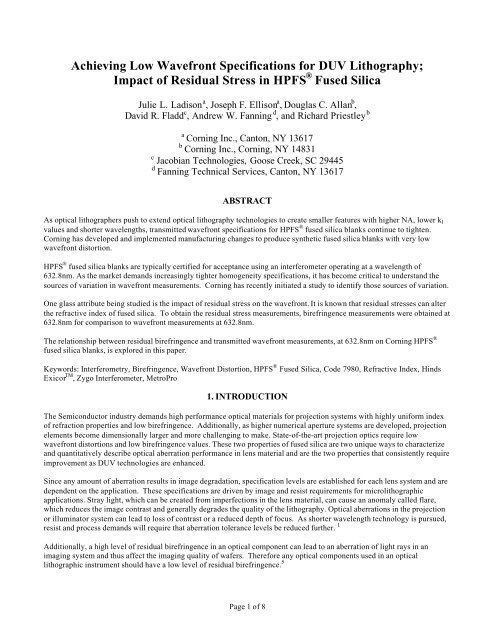
Achiev<strong>in</strong>g Low Wavefront Specifications for DUV Lithography;<br />
<strong>Impact</strong> <strong>of</strong> <strong>Residual</strong> <strong>Stress</strong> <strong>in</strong> <strong>HPFS</strong> ® <strong>Fused</strong> <strong>Silica</strong><br />
Julie L. Ladison a , Joseph F. Ellison a , Douglas C. Allan b ,<br />
David R. Fladd c , Andrew W. Fann<strong>in</strong>g d , and Richard Priestley b<br />
a<br />
Corn<strong>in</strong>g Inc., Canton, NY 13617<br />
b Corn<strong>in</strong>g Inc., Corn<strong>in</strong>g, NY 14831<br />
c Jacobian Technologies, Goose Creek, SC 29445<br />
d Fann<strong>in</strong>g Technical Services, Canton, NY 13617<br />
ABSTRACT<br />
As optical lithographers push to extend optical lithography technologies to create smaller features with higher NA, lower k 1<br />
values and shorter wavelengths, transmitted wavefront specifications for <strong>HPFS</strong> ® fused silica blanks cont<strong>in</strong>ue to tighten.<br />
Corn<strong>in</strong>g has developed and implemented manufactur<strong>in</strong>g changes to produce synthetic fused silica blanks with very low<br />
wavefront distortion.<br />
<strong>HPFS</strong> ® fused silica blanks are typically certified for acceptance us<strong>in</strong>g an <strong>in</strong>terferometer operat<strong>in</strong>g at a wavelength <strong>of</strong><br />
632.8nm. As the market demands <strong>in</strong>creas<strong>in</strong>gly tighter homogeneity specifications, it has become critical to understand the<br />
sources <strong>of</strong> variation <strong>in</strong> wavefront measurements. Corn<strong>in</strong>g has recently <strong>in</strong>itiated a study to identify those sources <strong>of</strong> variation.<br />
One glass attribute be<strong>in</strong>g studied is the impact <strong>of</strong> residual stress on the wavefront. It is known that residual stresses can alter<br />
the refractive <strong>in</strong>dex <strong>of</strong> fused silica. To obta<strong>in</strong> the residual stress measurements, birefr<strong>in</strong>gence measurements were obta<strong>in</strong>ed at<br />
632.8nm for comparison to wavefront measurements at 632.8nm.<br />
The relationship between residual birefr<strong>in</strong>gence and transmitted wavefront measurements, at 632.8nm on Corn<strong>in</strong>g <strong>HPFS</strong> ®<br />
fused silica blanks, is explored <strong>in</strong> this paper.<br />
Keywords: Interferometry, Birefr<strong>in</strong>gence, Wavefront Distortion, <strong>HPFS</strong> ® <strong>Fused</strong> <strong>Silica</strong>, Code 7980, Refractive Index, H<strong>in</strong>ds<br />
Exicor TM , Zygo Interferometer, MetroPro<br />
1. INTRODUCTION<br />
The Semiconductor <strong>in</strong>dustry demands high performance optical materials for projection systems with highly uniform <strong>in</strong>dex<br />
<strong>of</strong> refraction properties and low birefr<strong>in</strong>gence. Additionally, as higher numerical aperture systems are developed, projection<br />
elements become dimensionally larger and more challeng<strong>in</strong>g to make. State-<strong>of</strong>-the-art projection optics require low<br />
wavefront distortions and low birefr<strong>in</strong>gence values. These two properties <strong>of</strong> fused silica are two unique ways to characterize<br />
and quantitatively describe optical aberration performance <strong>in</strong> lens material and are the two properties that consistently require<br />
improvement as DUV technologies are enhanced.<br />
S<strong>in</strong>ce any amount <strong>of</strong> aberration results <strong>in</strong> image degradation, specification levels are established for each lens system and are<br />
dependent on the application. These specifications are driven by image and resist requirements for microlithographic<br />
applications. Stray light, which can be created from imperfections <strong>in</strong> the lens material, can cause an anomaly called flare,<br />
which reduces the image contrast and generally degrades the quality <strong>of</strong> the lithography. Optical aberrations <strong>in</strong> the projection<br />
or illum<strong>in</strong>ator system can lead to loss <strong>of</strong> contrast or a reduced depth <strong>of</strong> focus. As shorter wavelength technology is pursued,<br />
resist and process demands will require that aberration tolerance levels be reduced further. 1<br />
Additionally, a high level <strong>of</strong> residual birefr<strong>in</strong>gence <strong>in</strong> an optical component can lead to an aberration <strong>of</strong> light rays <strong>in</strong> an<br />
imag<strong>in</strong>g system and thus affect the imag<strong>in</strong>g quality <strong>of</strong> wafers. Therefore any optical components used <strong>in</strong> an optical<br />
lithographic <strong>in</strong>strument should have a low level <strong>of</strong> residual birefr<strong>in</strong>gence. 5<br />
Page 1 <strong>of</strong> 8
Due to these strong requirements, Corn<strong>in</strong>g cont<strong>in</strong>ues to deliver <strong>HPFS</strong> ® 7980 fused silica optics with these qualities by<br />
improv<strong>in</strong>g and develop<strong>in</strong>g manufactur<strong>in</strong>g processes to meet new specification requirements.<br />
For the optics manufacturer, it is important to understand the relationship between birefr<strong>in</strong>gence and wavefront distortion to<br />
determ<strong>in</strong>e cause and effect.<br />
What is considered a “low level <strong>of</strong> birefr<strong>in</strong>gence”? Is birefr<strong>in</strong>gence impact<strong>in</strong>g today’s wavefront measurements on fused<br />
silica blanks? What can photoelastic theory tell us about the relationships among stress, wavefront distortion, and<br />
birefr<strong>in</strong>gence? The results <strong>of</strong> this paper are <strong>in</strong>tended to enhance and expand our exist<strong>in</strong>g knowledge <strong>of</strong> these properties and<br />
determ<strong>in</strong>e if birefr<strong>in</strong>gence is a cause <strong>of</strong> wavefront distortion <strong>in</strong> <strong>HPFS</strong> ® blanks. This knowledge will determ<strong>in</strong>e which future<br />
actions are pursued to improve refractive <strong>in</strong>dex uniformity and reduce wavefront distortions.<br />
2.1 Interferometry Measurements<br />
2. MEASUREMENT TECHNIQUES<br />
Corn<strong>in</strong>g uses sophisticated <strong>in</strong>terferometer techniques to characterize and quantify optical aberrations. Fifteen samples were<br />
measured with a resolution <strong>of</strong> 1.11mm/pixel at the Corn<strong>in</strong>g Canton Plant <strong>in</strong> Canton, New York.<br />
The wavefront distortion, caused by refractive <strong>in</strong>dex <strong>in</strong>homogeneities, was measured us<strong>in</strong>g a Zygo Mark IV GPI phase<br />
measur<strong>in</strong>g <strong>in</strong>terferometer with a circularly polarized HeNe laser. The wavefront measurements were then analyzed us<strong>in</strong>g<br />
Zygo MetroPro s<strong>of</strong>tware, version 7.3.2. MetroPro is a GUI (Graphic User Interface) for operat<strong>in</strong>g Zygo <strong>in</strong>terferometers and<br />
analyz<strong>in</strong>g data.<br />
The lens blanks are thermally stabilized and made transparent by utiliz<strong>in</strong>g <strong>in</strong>dex-match<strong>in</strong>g oil. A HeNe laser beam is<br />
transmitted through a lens blank. While the laser beam is pass<strong>in</strong>g through the glass, the phase <strong>of</strong> the laser light is be<strong>in</strong>g<br />
altered due to the <strong>in</strong>dex <strong>of</strong> refraction variations. An <strong>in</strong>terference pattern is formed when the measur<strong>in</strong>g wavefront <strong>of</strong> the<br />
<strong>in</strong>terferometer comb<strong>in</strong>es with a reference wavefront. The pattern formed is <strong>in</strong>dicative <strong>of</strong> the phase variation and, therefore,<br />
the <strong>in</strong>dex variation. By mak<strong>in</strong>g measurements <strong>of</strong> this pattern, the <strong>in</strong>terferometer can determ<strong>in</strong>e what the relative <strong>in</strong>dex <strong>of</strong><br />
refraction is for a matrix <strong>of</strong> po<strong>in</strong>ts (or pixels) over the aperture <strong>of</strong> test. 2 The result is a refractive <strong>in</strong>dex map <strong>of</strong> the part which<br />
can be analyzed for wavefront distortions.<br />
Aberrations can be represented with Zernike polynomials, however for the purposes <strong>of</strong> this study, only the homogeneity<br />
(peak to valley) and RMS (root mean square) values were recorded.<br />
2.2 Birefr<strong>in</strong>gence Measurements<br />
The same parts measured for homogeneity were shipped to H<strong>in</strong>ds Instruments, Inc <strong>in</strong> Portland Oregon for birefr<strong>in</strong>gence<br />
measurements. A spac<strong>in</strong>g resolution <strong>of</strong> 5mm was utilized.<br />
H<strong>in</strong>ds Instruments has developed a new birefr<strong>in</strong>gence measurement <strong>in</strong>strument known as the EXICOR TM system. It employs<br />
photoelastic modulator (PEM) technology to achieve high sensitivity, repeatability, and fast measurements. The system<br />
simultaneously determ<strong>in</strong>es both the birefr<strong>in</strong>gent magnitude and direction <strong>in</strong> a sample. 3 The <strong>in</strong>strument employs a low<br />
birefr<strong>in</strong>gence photoelastic modulator for modulat<strong>in</strong>g the polarization states <strong>of</strong> a HeNe laser beam. After the modulated laser<br />
beam passes through the sample, two detect<strong>in</strong>g channels analyze the polarization change caused by the sample. H<strong>in</strong>ds’s<br />
EXICOR TM s<strong>of</strong>tware then calculates and analyzes the measurement data. 4 The Exicor TM system determ<strong>in</strong>es the residual<br />
birefr<strong>in</strong>gence <strong>in</strong> optical components with a sensitivity <strong>of</strong> 0.005nm for magnitude and
Maximum absolute birefr<strong>in</strong>gence values, <strong>in</strong> units <strong>of</strong> nm/cm, were recorded for this study.<br />
3. DATA<br />
Fifteen <strong>HPFS</strong> ® 7980 Excimer Grade fused silica samples were measured for birefr<strong>in</strong>gence and homogeneity at 632.8nm. The<br />
results are summarized <strong>in</strong> Figure 1. A 90% clear aperture was used to evaluate the data. The homogeneity values ranged<br />
from 0.37-0.74 ppm, RMS values ranged from 0.005-0.015 waves, and the maximum absolute birefr<strong>in</strong>gence values ranged<br />
from 0.07-0.45 nm/cm.<br />
Sample<br />
#<br />
Figure 1: Summary <strong>of</strong> Corn<strong>in</strong>g <strong>HPFS</strong> ® <strong>Fused</strong> <strong>Silica</strong> Homogeneity and Birefr<strong>in</strong>gence Measurements<br />
Diameter<br />
[mm]<br />
Thickness<br />
[mm]<br />
Clear<br />
Aperture<br />
[mm]<br />
Dn<br />
[ppm]<br />
RMS<br />
[waves]<br />
Maximum Absolute<br />
Birefr<strong>in</strong>gence<br />
[nm/cm]<br />
A 195 51.1 176 0.37 0.005 0.13<br />
B 175 48.2 158 0.56 0.008 0.26<br />
C 195 68.1 176 0.74 0.015 0.17<br />
D 200 55.1 180 0.47 0.007 0.40<br />
E 175 50.3 158 0.50 0.007 0.29<br />
F 180 49.8 162 0.41 0.009 0.19<br />
G 230 45.2 207 0.64 0.010 0.40<br />
H 230 45.1 207 0.72 0.010 0.07<br />
I 220 55.7 198 0.52 0.009 0.40<br />
J 220 54.8 198 0.48 0.009 0.45<br />
K 175 49.5 158 0.63 0.010 0.15<br />
L 220 45.1 198 0.43 0.006 0.30<br />
M 180 50.5 162 0.39 0.005 0.21<br />
N 160 47.3 144 0.39 0.005 0.26<br />
O 175 51.9 158 0.55 0.007 0.29<br />
Average 195 51.2 176 0.52 0.008 0.26<br />
Maximum 230 68.1 207 0.74 0.015 0.45<br />
M<strong>in</strong>imum 160 45.1 144 0.37 0.005 0.07<br />
Page 3 <strong>of</strong> 8
4. RESULTS<br />
4.1 Results <strong>of</strong> Birefr<strong>in</strong>gence Measurements<br />
The birefr<strong>in</strong>gence <strong>of</strong> <strong>HPFS</strong> ® fused silica is extremely low. The average maximum absolute birefr<strong>in</strong>gence was 0.26 nm/cm for<br />
all 15 parts. The maximum was 0.45nm/cm and the m<strong>in</strong>imum was 0.07nm/cm. Typically, higher birefr<strong>in</strong>gence values can be<br />
observed on the circumference <strong>of</strong> each <strong>HPFS</strong> ® fused silica due to mechanical gr<strong>in</strong>d<strong>in</strong>g operations on the outer diameter <strong>of</strong> the<br />
parts. These stresses are not observed with<strong>in</strong> the clear aperture <strong>of</strong> the parts. This edge stress can be observed <strong>in</strong> Figures 2B,<br />
3B, and 4B.<br />
4.2 Results <strong>of</strong> Homogeneity Measurements<br />
The homogeneity measurements <strong>of</strong> the <strong>HPFS</strong> ® fused silica blanks were typical for the part sizes tested. The average<br />
homogeneity value was 0.52 ppm for all 15 parts. The maximum was 0.74ppm and the m<strong>in</strong>imum was 0.37ppm.<br />
4.3 Influence <strong>of</strong> <strong>Stress</strong> <strong>in</strong> Interferometry: Explor<strong>in</strong>g Photoelastic Relations Between <strong>Stress</strong> and Optical Index Changes<br />
In simple terms, birefr<strong>in</strong>gence is the difference <strong>of</strong> two <strong>in</strong>dices <strong>of</strong> refraction whereas wavefront measurements are a measure<br />
<strong>of</strong> the variation <strong>in</strong> average <strong>in</strong>dex.<br />
There are two set <strong>of</strong> constants that are typically used to describe photoelastic behavior <strong>of</strong> materials. These are the stressoptical<br />
constants, which are denoted as q mn , and the stra<strong>in</strong>-optical constants, which are denoted p mn . In an optically isotropic<br />
medium, only two components <strong>of</strong> these two tensors are unique. 6 These may be taken as the 11 and 12 components: q 11 and<br />
q 12 or p 11 and p 12 .<br />
For the follow<strong>in</strong>g discussion, the pr<strong>in</strong>ciple stress axes are those coord<strong>in</strong>ate axes that make the stress tensor a diagonal matrix.<br />
We denote them as x, y, and z, but <strong>in</strong> a cyl<strong>in</strong>drical lens blank one usually replaces x and y with radial and tangential<br />
coord<strong>in</strong>ates. Other than notation, none <strong>of</strong> the equations would be affected by such a choice.<br />
The photoelastic tensor components are def<strong>in</strong>ed <strong>in</strong> terms <strong>of</strong> distortions <strong>of</strong> the “ellipsoid <strong>of</strong> wave normals”, which is actually a<br />
sphere <strong>in</strong> an isotropic, stress-free sample. 6 They are expressed <strong>in</strong> terms <strong>of</strong> variations <strong>in</strong> 1/ε, where ε=dielectric constant. The<br />
dielectric constant ε is related to the <strong>in</strong>dex <strong>of</strong> refraction n by<br />
ε = n 2 (1)<br />
To exam<strong>in</strong>e variations <strong>in</strong> n <strong>in</strong>stead <strong>of</strong> variations <strong>in</strong> 1/ ε, we use the relation<br />
∆<br />
= −<br />
2<br />
1 3<br />
n 0<br />
1<br />
⎜<br />
⎝ ε<br />
⎛ ⎞<br />
( ) ∆ ⎟<br />
⎠<br />
n (2)<br />
where n 0 is the <strong>in</strong>dex <strong>of</strong> refraction <strong>in</strong> the absence <strong>of</strong> stress or stra<strong>in</strong>.<br />
From the def<strong>in</strong>ition <strong>of</strong> the stra<strong>in</strong>-optical constants and the discussion above, and for isotropic materials, we have the relations<br />
(∆n) x = (-n 0 3 /2) (p 11 e x + p 12 e y + p 12 e z )<br />
(∆n) y = (-n 0 3 /2) (p 12 e x + p 11 e y + p 12 e z )<br />
(∆n) z = (-n 0 3 /2) (p 12 e x + p 12 e y + p 11 e z ) (3)<br />
where e x , e y , and e z are the stra<strong>in</strong>s along the pr<strong>in</strong>ciple axes (denoted x, y, and z), and (∆n) x is the <strong>in</strong>dex change due to the<br />
stra<strong>in</strong>s for light polarized along pr<strong>in</strong>ciple axis x, (∆n) y for light polarized along y, and (∆n) z for light polarized along z.<br />
Page 4 <strong>of</strong> 8
The analogous expressions <strong>in</strong> terms <strong>of</strong> stress <strong>in</strong>stead <strong>of</strong> stra<strong>in</strong> are<br />
(∆n) x = (-n 3 0 /2) (q 11 σ x + q 12 σ y + q 12 σ z )<br />
(∆n) y = (-n 3 0 /2) (q 12 σ x + q 11 σ y + q 12 σ z )<br />
(∆n) z = (-n 3 0 /2) (q 12 σ x + q 12 σ y + q 11 σ z )<br />
(4a)<br />
(4b)<br />
(4c)<br />
where the σ’s are now stresses along the pr<strong>in</strong>ciple axes.<br />
<strong>Stress</strong> and stra<strong>in</strong> are related through the elastic properties <strong>of</strong> the material. For an isotropic material, only the Young’s<br />
modulus E and the Poisson ratio ν are needed, and the relations are<br />
e x = (1/E) (σ x – ν (σ y +σ z ))<br />
e y = (1/E) (σ y – ν (σ z +σ x ))<br />
e z = (1/E) (σ z – ν (σ x +σ y )) (5)<br />
The two descriptions <strong>of</strong> <strong>in</strong>dex change <strong>in</strong> Eqs. (3) and (4) must agree and be consistent with Eqs.(5), so we can deduce the<br />
relations between stra<strong>in</strong>-optic and stress-optic coefficients<br />
q 11 = (1/E) (p 11 – 2 ν p 12 )<br />
q 12 = (1/E) (p 12 – ν (p 11 +p 12 )) (6)<br />
If light is travel<strong>in</strong>g down the z axis, then the birefr<strong>in</strong>gence <strong>of</strong> the sample is the difference between (∆n) x and (∆n) y , i.e.<br />
BR = (∆n) x - (∆n) y = (-n 0 3 /2) (q 11 -q 12 ) (σ x -σ y ) (7)<br />
where σ x and σ y are now averaged along the light path through the sample.<br />
Several other relations can be derived from the equations above. For example, <strong>in</strong> most cases the stra<strong>in</strong> can be approximated<br />
as be<strong>in</strong>g isotropic <strong>in</strong> each small region <strong>of</strong> the sample (e.g. with<strong>in</strong> each element <strong>of</strong> a f<strong>in</strong>ite element calculation). This leads to<br />
the isotropic approximation for <strong>in</strong>dex variation<br />
(∆n) iso = (-n 0 3 /2) ((p 11 +2p 12 )/3) (e x +e y +e z ) (8)<br />
The sum <strong>of</strong> the three stra<strong>in</strong>s (e x +e y +e z ) is a fractional volume change, or the negative <strong>of</strong> a fractional density change. Thus<br />
Eq.(8) shows a l<strong>in</strong>ear proportionality between a density <strong>in</strong>crease and an isotropic <strong>in</strong>crease <strong>in</strong> <strong>in</strong>dex <strong>of</strong> refraction.<br />
Consider<strong>in</strong>g light propagat<strong>in</strong>g down the z axis, we have<br />
(∆n) avg = (∆n x + ∆n y )/2 = (-n 0 3 /2) ((q 11 +q 12 )(σ x +σ y )/2 + q 12 σ z ) (9)<br />
This expression should represent the refractive <strong>in</strong>dex contribution to wavefront distortion measured by circularly polarized<br />
light used <strong>in</strong> <strong>in</strong>terferometry. The measurement would actually detect (∆n) avg <strong>in</strong>tegrated through the sample thickness, so the<br />
result depends on all three pr<strong>in</strong>ciple stresses <strong>in</strong>tegrated through the sample thickness.<br />
Page 5 <strong>of</strong> 8
Focus<strong>in</strong>g on stress and its connections to <strong>in</strong>terferometry and birefr<strong>in</strong>gence, for light travel<strong>in</strong>g down the z axis, Eqs.(4a), (4b),<br />
(7), and (9) are important.<br />
(∆n) x = (-n 3 0 /2) (q 11 σ x + q 12 σ y + q 12 σ z )<br />
(4a)<br />
(∆n) y = (-n 3 0 /2) (q 12 σ x + q 11 σ y + q 12 σ z )<br />
(4b)<br />
BR = (∆n) x - (∆n) y = (-n 3 0 /2) (q 11 -q 12 ) (σ x -σ y ) (7)<br />
(∆n) avg = (∆n x + ∆n y )/2 = (-n 3 0 /2) ((q 11 +q 12 )(σ x +σ y )/2 + q 12 σ z ). (9)<br />
Eqs. (7) and (9) relate to birefr<strong>in</strong>gence and (circularly polarized) <strong>in</strong>terferometry measurements, respectively.<br />
The birefr<strong>in</strong>gence measurement depends only on the difference <strong>in</strong> pr<strong>in</strong>ciple stresses (σ x -σ y ), while (∆n) avg or (∆n) x , (∆n) y<br />
depend <strong>in</strong> a more complicated way on all three stress components σ x , σ y , and σ z .<br />
From Eqs. (4a) and (4b), the knowledge <strong>of</strong> the two variables (∆n) x and (∆n) y is not enough to determ<strong>in</strong>e the three stress<br />
variables σ x , σ y , and σ z . Thus, <strong>in</strong> pr<strong>in</strong>ciple, <strong>in</strong>terferometry and birefr<strong>in</strong>gence measurements down a s<strong>in</strong>gle axis do not give<br />
enough <strong>in</strong>formation to determ<strong>in</strong>e the pr<strong>in</strong>ciple stresses. In practice, however, one or even two <strong>of</strong> the pr<strong>in</strong>ciple stresses may<br />
be small enough to ignore, <strong>in</strong> which case the other two or one stresses can be determ<strong>in</strong>ed from knowledge <strong>of</strong> (∆n) x and (∆n) y .<br />
What is the po<strong>in</strong>t?<br />
Because wavefront distortion and birefr<strong>in</strong>gence both <strong>in</strong>volve variations <strong>in</strong> the <strong>in</strong>dex <strong>of</strong> refraction, one may be tempted to<br />
th<strong>in</strong>k that one causes the other. This is false. One may be tempted to th<strong>in</strong>k that they are always strongly correlated, for<br />
example, both caused by the same underly<strong>in</strong>g stresses. It is true that stress can cause both wavefront distortion and<br />
birefr<strong>in</strong>gence, but the degree <strong>of</strong> correlation between the two can be highly variable. The po<strong>in</strong>t is this: under some<br />
circumstances, wavefront distortion and birefr<strong>in</strong>gence should be strongly correlated, while <strong>in</strong> other circumstances, they<br />
should be uncorrelated.<br />
For example, look<strong>in</strong>g at Eqs. (7) and (9), suppose a stress σ z was developed through process<strong>in</strong>g. This stress would have no<br />
effect at all on the birefr<strong>in</strong>gence (as measured down the z axis), but would <strong>in</strong>deed change (∆n) avg and thus alter the wavefront<br />
distortion. On the other hand, suppose we exam<strong>in</strong>e wavefront distortion and birefr<strong>in</strong>gence near the edge <strong>of</strong> a lens blank. In<br />
this case, we can usually treat the pr<strong>in</strong>ciple axes as radial and tangential, and the radial stress has to vanish as we approach<br />
the edge. Tak<strong>in</strong>g the tangential stress as σ x , we see from Eqs. (7) and (9) that a larger σ x will alter both the birefr<strong>in</strong>gence and<br />
(∆n) avg together. Thus, <strong>in</strong> this case, they will be correlated. As a third example, suppose σ x and σ y are both <strong>in</strong>creased<br />
together. Then the birefr<strong>in</strong>gence is unaffected but the wavefront distortion is altered <strong>in</strong> a way that is uncorrelated to<br />
birefr<strong>in</strong>gence. F<strong>in</strong>ally, an obvious connection between stress-<strong>in</strong>duced wavefront changes and birefr<strong>in</strong>gence is shown <strong>in</strong> the<br />
laser compaction <strong>of</strong> fused silica, both <strong>in</strong> the theoretical model and <strong>in</strong> the experimental measurements. 7,8<br />
Of the four cases discussed, only two predict a strong correlation between wavefront distortion and birefr<strong>in</strong>gence. The real<br />
answer for any given process or thermal history must be determ<strong>in</strong>ed by measurements <strong>of</strong> both birefr<strong>in</strong>gence and wavefront<br />
distortion on the same pieces <strong>of</strong> glass. Because the radial stress vanishes near the edge, the edge region especially can be<br />
evaluated for correlations between birefr<strong>in</strong>gence and wavefront distortion. In a process that produces larger tangential<br />
stresses, a correlation is expected. In our samples, with low levels <strong>of</strong> birefr<strong>in</strong>gence as shown <strong>in</strong> Figures 2B, 3B and 4B, there<br />
is no correlation.<br />
Page 6 <strong>of</strong> 8
4.4. Typical Wavefront and Birefr<strong>in</strong>gence Map Patterns<br />
The birefr<strong>in</strong>gence map from the H<strong>in</strong>ds Exicor TM system was visually compared to the Zygo MetroPro s<strong>of</strong>tware wavefront<br />
distortion map for each part. Figures 2-4 show typical examples <strong>of</strong> the wavefront map (on left, clear aperture) compared to<br />
the birefr<strong>in</strong>gence map (on right, full aperture). In these examples, there is no relationship between the homogeneity and<br />
birefr<strong>in</strong>gence patterns.<br />
Figure 2A: Sample F: Zygo Wavefront Map:<br />
∆n ≤ 0.41ppm<br />
Figure 2B: Sample F: H<strong>in</strong>ds Birefr<strong>in</strong>gence Map:<br />
Birefr<strong>in</strong>gence ≤ 0.19nm/cm<br />
Figure 3A: Sample M: Zygo Wavefront Map<br />
∆n ≤ 0.39ppm<br />
Figure 3B: Sample M: H<strong>in</strong>ds Birefr<strong>in</strong>gence Map:<br />
Birefr<strong>in</strong>gence ≤ 0.21 nm/cm<br />
Figure 4A: Sample E: Zygo Wavefront Map<br />
∆n ≤ 0.50 ppm<br />
Figure 4B: Sample E: H<strong>in</strong>d’s Birefr<strong>in</strong>gence Map<br />
Birefr<strong>in</strong>gence ≤ 0.29nm/cm<br />
Page 7 <strong>of</strong> 8
5. CONCLUSIONS<br />
In simple terms, birefr<strong>in</strong>gence is the difference <strong>of</strong> two <strong>in</strong>dices <strong>of</strong> refraction (for orthogonal polarizations) whereas wavefront<br />
measurements are a measure <strong>of</strong> the variation <strong>in</strong> average <strong>in</strong>dex. While both effects are related to <strong>in</strong>dex variations, and both<br />
can be <strong>in</strong>fluenced by stress, their degree <strong>of</strong> correlation can range from perfectly correlated to uncorrelated, depend<strong>in</strong>g on<br />
circumstances.<br />
Our study concludes that for Excimer grade <strong>HPFS</strong> ® fused silica with typical homogeneity values less than 0.75 ppm and<br />
birefr<strong>in</strong>gence values less than 0.45nm/cm, there is no correlation between homogeneity and birefr<strong>in</strong>gence measurements.<br />
ACKNOWLEDGMENTS<br />
We gratefully acknowledge the support <strong>of</strong> Baoliang (Bob) Wang and Andy Kaplan <strong>of</strong> H<strong>in</strong>ds Instruments, Inc., for their<br />
support <strong>in</strong> obta<strong>in</strong><strong>in</strong>g the birefr<strong>in</strong>gence measurements used <strong>in</strong> this paper.<br />
REFERENCES<br />
1. J.R. Sheats, B. W. Smith, Microlithography Science and Technology, pages 27, 28, 223, 195-268, Marcel Dekker, Inc,<br />
New York, (1998).<br />
2. Zygo Corporation, Fundamentals <strong>of</strong> Interferometry and Optical Test<strong>in</strong>g I, Customer Education, page 35, (1996)<br />
3. B. Wang, “Measurement <strong>of</strong> Excimer Laser Induced Birefr<strong>in</strong>gence <strong>in</strong> <strong>Fused</strong> <strong>Silica</strong> and Calcium Fluoride”, <strong>in</strong> Metrology,<br />
Inspection, and Process Control for Microlithography XIV, Neal T. Sullivan, Editor, Proceed<strong>in</strong>gs <strong>of</strong> SPIE Volume 3998<br />
(2000).<br />
4. B. Wang, T.C. Oakburg, “ A new <strong>in</strong>strument for measur<strong>in</strong>g both the magnitude and angle <strong>of</strong> low level l<strong>in</strong>ear<br />
birefr<strong>in</strong>gence”, Review <strong>of</strong> Scientific Instruments, American Institute <strong>of</strong> Physics, Volume 10, Number 10, pages 3847-3854<br />
(October 1999).<br />
5. B. Wang, P. Troccolo, “Measurement <strong>of</strong> <strong>Residual</strong> Birefr<strong>in</strong>gence <strong>in</strong> Photomask Blanks”, Part <strong>of</strong> the 19 th Annual BACUS<br />
Symposium on Photomask Technology, Proceed<strong>in</strong>gs <strong>of</strong> SPIE Volume 3873, pages 544-553, (1999).<br />
6. M. Born and E. Wolf, Pr<strong>in</strong>ciples <strong>of</strong> Optics, 6 th edition, Pergamon Press, New York, pages 703-705, (1980).<br />
7. D. C. Allan, C. Smith, and N. F. Borrelli, “Measurement and analysis <strong>of</strong> compaction <strong>in</strong> fused silica”, Symposium on Laser<br />
Induced Damage <strong>in</strong> Optical Materials, Proceed<strong>in</strong>gs <strong>of</strong> SPIE Volume 3578, 16-26 (1998).<br />
8. N. F. Borrelli, C. Smith, D. C. Allan, and T. P. Seward III, “Densification <strong>of</strong> fused silica under 193-nm excitation”,<br />
Journal <strong>of</strong> the Optical Society <strong>of</strong> America, Volume 14, 1606-1615 (1997). See especially Figs. 6 and 7.<br />
Page 8 <strong>of</strong> 8