Viscosity and drag
Viscosity and drag
Viscosity and drag

You also want an ePaper? Increase the reach of your titles
YUMPU automatically turns print PDFs into web optimized ePapers that Google loves.
first name (print) last name (print) student number grade<br />
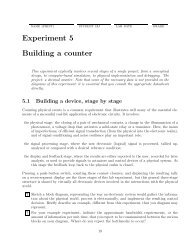
Experiment 5<br />
<strong>Viscosity</strong> <strong>and</strong> <strong>drag</strong><br />
Drag force arises when an object moves through a fluid or, equivalently, when fluid flows past an object.<br />
In general, the <strong>drag</strong> force grows larger with increased flow velocity, but viscosity is a complex phenomenon<br />
that cannot be reduced to the simple relationship “<strong>drag</strong> force is proportional to velocity”.<br />
The origin of the <strong>drag</strong> force F d lies in the need to displace the particles of the fluid out of the way<br />
of a moving object. At low velocities the movement of the fluid is smooth (laminar) <strong>and</strong> the faster the<br />
object moves, the greater is the amount of fluid that has to get out of the way, giving rise to the linear<br />
relationship<br />
F (viscous)<br />
d<br />
= aηv<br />
where v is the velocity of the object relative to the fluid, η is the coefficient of viscosity, <strong>and</strong> a is the “size”<br />
of the object; for a sphere of radius r, a = 6πr. The larger the size, the greater is the amount of fluid that<br />
needs to get out of the way, hence it is not surprising that the relationship is linear with respect to a as<br />
well.<br />
The story gets far more complicated for higher velocities, unusual object shapes, of unusual fluids. At<br />
higher velocities or around oddly-shaped objects the flow stops being smooth <strong>and</strong> turns turbulent, which<br />
requires more energy <strong>and</strong> causes the <strong>drag</strong> force to switch to the quadratic regime, where F d ∝ v 2 ,<br />
F (inertial)<br />
d<br />
= S ρ 0v 2<br />
.<br />
2<br />
Note that this expression represents an inertial rather than a viscous force, <strong>and</strong> instead of the the viscosity,<br />
η, the fluid density, ρ 0 , enters the formula. S is the cross-sectional area of the moving object.<br />
An empirical parameter called the Reynolds number determines which of the above two terms dominates:<br />
R = dρv<br />
η<br />
where for a simple sphere, the diameter d(= 2r) is the obvious definition of the “size” of the particle 1 . For<br />
R < 1, the viscous <strong>drag</strong> dominates (<strong>and</strong> thus there is no inertial coasting), while for R > 1000 the viscous<br />
<strong>drag</strong> is completely negligible as compared to the inertial <strong>drag</strong>.<br />
At higher velocities still, in compressible fluids one needs to account for the compression waves that get<br />
created (e.g. the sonic boom of a supersonic aircraft), <strong>and</strong> in incompressible fluids the surface layer of the<br />
fluid may lose contact with the rapidly moving object creating local vacuum (e.g. cavitation on the surface<br />
of the blades of naval propellers). Unusual fluids such as solutions of long polymers may experience flow in<br />
directions other than the direction of motion, as the entangled polymer molecules transmit the movement<br />
of the object to remote areas of the fluid <strong>and</strong> back. The fluid constrained into finite-size channels <strong>and</strong> tubes<br />
1 For other shapes, an equivalent “hydrodynamic radius” r h is used instead of r<br />
45
46 EXPERIMENT 5. VISCOSITY AND DRAG<br />
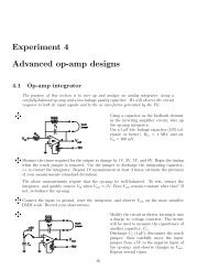
Figure 5.1: Drag coefficient on a sphere in an infinite fluid, as a function of the Reynolds number<br />
also behaves differently from an infinitely-broad medium through which a small-size sphere is traveling.<br />
There are corrections that must account for all of these details.<br />
A convenient way to express just such a correction is through an empirical factor called “the coefficient<br />
of <strong>drag</strong>”, C d , which can be measured experimentally <strong>and</strong> account for the details of shape, size, <strong>and</strong> the<br />
nature of the media through which an object is traveling. This dimensionless coefficient is well-known <strong>and</strong><br />
its tabulated values can be found in h<strong>and</strong>books. As a function of the Reynolds number, the experimentally<br />
measured values of the <strong>drag</strong> coefficient, C d , constitute the so-called “st<strong>and</strong>ard <strong>drag</strong> curve” shown in Fig. 5.1.<br />
For a small sphere traveling through an infinitely broad fluid, this C d provides an excellent agreement with<br />
the experimental <strong>drag</strong> force:<br />
F d = K f C d S ρ 0v 2<br />
2 , C d = C d (R) (5.1)<br />
The finite-size correction coefficient, K f , describes how this equation is modified by the boundary conditions<br />
of a fluid confined in a finite-size vessel. For a sphere of diameter d traveling axially through a fluid channel<br />
(a pipe) of diameter D, a dimensionless ratio x = d/D can be used to approximate this correction coefficient<br />
to within 6% via 2 1<br />
K f =<br />
1 − αxα, α = 1.60 for x ≤ 0.6 , (5.2)<br />
in the range of Reynolds number values of 10 2 < R < 10 5 .<br />
2 R.Clift, J.R.Grace, <strong>and</strong> M.E.Weber. Bubbles, Drops, <strong>and</strong> Particles, p.226. Academic Press, 1978
47<br />
For an object at rest, there is no <strong>drag</strong> force. As we apply a force to an object, it experiences an<br />
acceleration, its velocity grows, <strong>and</strong> with it grows the <strong>drag</strong> force that is directed opposite the velocity. This<br />
<strong>drag</strong> force counteracts the applied force <strong>and</strong> reduces the net force <strong>and</strong> the object’s acceleration. Eventually,<br />
velocity increases to the point where the <strong>drag</strong> force is exactly matched to the applied force, bringing the<br />
net force to zero. From this point on, the object is in equilibrium, there is no acceleration, <strong>and</strong> the velocity<br />
remains constant, equal to its steady-state value called the terminal velocity, or v t . For example, if an<br />
object is in a free fall through a fluid, this equilibrium condition corresponds to the weight of the object<br />
exactly equal to the viscous force:<br />
F d = W .<br />
When the fluid in question is a gas such as air, the buoyant force F b — equal to the weight of the displaced<br />
gas — is tiny <strong>and</strong> can be neglected. When the fluid is a more dense substance such as water, the above<br />
equation may need to be modified to include the buouyant correction due to the displacement of the fluid<br />
by the object<br />
F d = W − F b = m object g − m fluid g = m object g(1 − ρ 0 /ρ) (5.3)<br />
where ρ is the density of the material of the object <strong>and</strong> ρ 0 is the density of the fluid. As you can see, only<br />
the ratio of the two densities enters into the expresiion since the volumes of the object <strong>and</strong> of the fluid it<br />
displaces are the same. For example, for an Al ball in water, ρ 0 = 1.00×10 3 kg/m 3 <strong>and</strong> ρ = 2.70×10 3 kg/m 3 .<br />
In this experiment you will explore this relationship by varying the force <strong>and</strong> measuring the terminal<br />
velocity of several spheres of different size.<br />
Review questions<br />
• What are the units of the viscosity coefficient η?<br />
......................................................................<br />
• What is the known value of η for water at room temperature? Cite the source of your value.<br />
......................................................................<br />
• In terms of its diameter d, what are the cross-sectional area S <strong>and</strong> the volume V of a sphere?<br />
S = ......................................................................<br />
V = ......................................................................<br />
• For a sphere of 1-cm radius moving through water at 1 m/s, calculate the Reynolds number R. What<br />
are the dimensions of R?<br />
......................................................................
48 EXPERIMENT 5. VISCOSITY AND DRAG<br />
• For the above sphere, which <strong>drag</strong> force (inertial or viscous) dominates? What is the expected coefficient<br />
of <strong>drag</strong>, C d ?<br />
......................................................................<br />
......................................................................<br />
CONGRATULATIONS! YOU ARE NOW READY TO PROCEED WITH THE EXPERIMENT!<br />
Procedure <strong>and</strong> analysis<br />
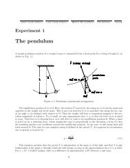
The experimental apparatus consists of two different-size metal spheres, a long cylindrical container filled<br />
with water, a pulley system with a weight platform <strong>and</strong> variable weights, an ultrasonic position sensor, a<br />
digital weight scale, a micrometer.<br />
Figure 5.2: The apparatus for measuring the <strong>drag</strong> force of the fluid on a moving sphere<br />
• Using a digital scale, weigh separately both spheres <strong>and</strong> the weight platform. You may also want to
49<br />
verify the exact values of the various weights in the weight set.<br />
W small = .............. ±............. W large = .............. ±.............<br />
W platform = .............. ±............. W “10 g” = .............. ±.............<br />
W “20 g” = .............. ±............. W “50 g” = .............. ±.............<br />
....................................... .......................................<br />
• Using the micrometer, measure the diameter d of each sphere <strong>and</strong> calculate their cross-sectional area<br />
S = πd 2 /4.<br />
d small = .............. ±............. d large = .............. ±.............<br />
S small = .............. ±............. S large = .............. ±.............<br />
• Measure <strong>and</strong> record the inner diameter D of the plastic cylinder filled with water. Verify that the<br />
cross-section is circular by measuring the diameter in a few different directions across the cylinder.<br />
Calculate the value of the parameter x = d/D for both spheres.<br />
..............................................................................<br />
• Select one of the spheres, adjust the length of the string so that the weight platform is at least 30 cm<br />
above the ultrasonic detector at its lowest position, <strong>and</strong> a few cm below the pulley at its highest<br />
position (i.e. when the sphere hits the bottom of the cylinder). Vary the weight you place on the<br />
weight platform (use single weights or their combinations), <strong>and</strong> measure a trace of position as a<br />
function of time as you let go of the string. Using Physica Online interface, each time gather about<br />
a hundred points spread out over the duration of the motion. For small weights (less that the weight<br />
of the sphere minus the buoyant force) the sphere will travel downward when released so start withe<br />
sphere at the top of the cylinder. For larger weights, the sphere will travel upward so start with the<br />
sphere at the bottom of the cylinder.<br />
For each data set, identify the linear part of the trace, where the position-vs-time graph is a straight<br />
line, <strong>and</strong> fit only this range of data to a straight-line equation, A*(x-B)*(x>X min )*(x
50 EXPERIMENT 5. VISCOSITY AND DRAG<br />
m, pull mass v t , small sphere v t , large sphere<br />
• From the free-body diagram of Fig.5.2, drawn for the case of the sphere traveling downward as<br />
appropriate for the small pull mass of the counterweight, when v = v t = const,<br />
<strong>and</strong> thus<br />
+T − W counterweight − W platform = 0<br />
F d + F b + W counterweight + W platform − W sphere = 0 .<br />
Denoting the pull mass of the counterweight as m, the mass of the weight platform as m p , the mass<br />
of the sphere as m s , <strong>and</strong> using the expressions of Eqs. 5.1 <strong>and</strong> 5.3 we obtain<br />
K f C d S ρ 0vt<br />
2 (<br />
= m s g 1 − ρ )<br />
0<br />
− m p g − mg<br />
2<br />
ρ<br />
Dividing through by g we obtain<br />
m = m 0 − K fC d Sρ 0<br />
vt 2 ,<br />
2g<br />
where m 0 = m s (1 − ρ 0 /ρ) − m p . For each of the spheres, record the pull mass used, m, as a function<br />
of the measured terminal velocity, v t .<br />
• Repeat for the sphere traveling upward; you need to re-draw the free-body diagram of Fig.5.2 as<br />
appropriate for this case. Remember that the <strong>drag</strong> force is always opposite to the velocity of the<br />
object moving through the fluid.<br />
• Using the data obtained for both direction of travel, enter the values obtained in the previous steps<br />
into Physica Online <strong>and</strong> plot m vs. v t . Fit to a quadratic expression, A+B*sign(x*x,x) (the function<br />
sign() here accounts for a change in the direction of the <strong>drag</strong> force as v t changes sign).<br />
Report the results for both spheres. Correct for the finite size of the water pipe (K F will be different<br />
for the two spheres), <strong>and</strong> see if the <strong>drag</strong> coefficient you measure is the same in both cases. Compare<br />
the calculated C d with the st<strong>and</strong>ard <strong>drag</strong> curve of Fig. 5.1 <strong>and</strong> comment on any discrepancies.<br />
B±∆B K F ± 6% C d ± ∆C d<br />
small sphere<br />
large sphere<br />
average — —<br />
IMPORTANT: BEFORE LEAVING THE LAB, HAVE A T.A. INITIAL YOUR WORKBOOK!
51<br />
Discussion<br />
To complete this lab, submit a typed or neatly written Discussion of the results of the experiment (doublespaced,<br />
400 to 600 words). Attach your computer printouts <strong>and</strong> worksheets to this Discussion. Discuss<br />
the following issues as part of your Discussion; as always this is not a complete list:<br />
• What is the physical meaning of the fit parameter A ?<br />
• From the shape of the plot of m vs. v t , is there any evidence of an additional force due to the friction<br />
in the pulleys? How would you estimate this force?<br />
• How does your value of C d compare to the known values? What are the likely reasons for the<br />
discrepancy, if any?