61 Tabletop Stand: PDK-TS01 - Pioneer
61 Tabletop Stand: PDK-TS01 - Pioneer
61 Tabletop Stand: PDK-TS01 - Pioneer

You also want an ePaper? Increase the reach of your titles
YUMPU automatically turns print PDFs into web optimized ePapers that Google loves.
<strong>Tabletop</strong> <strong>Stand</strong>: <strong>PDK</strong>-<strong>TS01</strong><br />
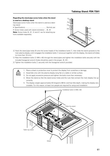
Regarding the stand pipe screw holes when the stand<br />
is used as a desktop stand<br />
<strong>Stand</strong> pipe screw holes when the stand is used as a desktop<br />
stand<br />
• Specifications.............................................. Normal use<br />
• Screw holes used with stand orientation ... B, B'<br />
Note: Screw holes A, A', C and C' are for attaching options<br />
available separately.<br />
C<br />
A<br />
B<br />
C´<br />
B´<br />
A´ C<br />
B<br />
B´<br />
A<br />
C´<br />
A´<br />
2 Hook the stand pipe holes B onto the screw heads of the installation bolts 1, then slide the stand upwards to the<br />
main plasma display until it engages the installation bolts 1 (once put together with the display, the stand will slides<br />
no more than 19 mm).<br />
3 Pass the installation bolts 2 (M8 × 40) through the stand pipes and tighten the installation bolts securely with the<br />
included hexagonal wrench (holes should be used in the proper, B, B').<br />
4 Tighten the installation bolts 1 securely with the hexagonal wrench provided.<br />
Notes<br />
1. Place a sheet or protective cover to protect the display from scratches or damage.<br />
2. Assemble only with the plasma display lying flat on a table or similar surface.<br />
3. Do not apply excessive pressure and tighten the bolts more than necessary.<br />
4. Move the stand so that the stand screw holes and the nuts that connect the main display line up<br />
correctly.<br />
5. The display weighs approximately 40 kilograms (88 lb.) and has little depth, making the display very<br />
unstable. For this reason, at least two people are required for setup and installation.<br />
Installation bolts 2 (M8 × 40)<br />
Slide the stand<br />
Table top stand<br />
Sheet<br />
<strong>61</strong>
<strong>Tabletop</strong> <strong>Stand</strong>: <strong>PDK</strong>-<strong>TS01</strong><br />
2) Instructions for using the main display packing material as a stand for the working on the display<br />
Main plasma display packaging setup<br />
Outer box<br />
Inner box frame<br />
Pad<br />
Pad<br />
Mirror mat<br />
Plasma display<br />
1 Construct the stand for the plasma display using the inner box frame and pads shown in the figure above (all pads are<br />
identical).<br />
Pads<br />
Inner box frame<br />
2 Set the plasma display down on the pads as shown in the figure below.<br />
Plasma display<br />
Mirror mat<br />
Inner box frame topped by two pads<br />
3 Follow the instructions in Steps 1-4 in "Normal Installation" to attach the stand to the plasma display.<br />
62
<strong>Tabletop</strong> <strong>Stand</strong>: <strong>PDK</strong>-<strong>TS01</strong><br />
After assembling, connect the stand to the floor to prevent from falling over.<br />
7 Stabilizing to the floor<br />
7 How to use the stabilization bolts<br />
÷ Use screws (sold separately) to attach and stabilize<br />
the stand.<br />
1. Attach the included bolts that prevent the display<br />
from falling over.<br />
2. Stabilize the display by connecting to a wall or<br />
standing beam with a strong cord.<br />
(Repeat the same steps in the laterally direction to<br />
stabilize the assembly to the left and right.)<br />
Use cord and hooks that are available on the market<br />
(sold separately).<br />
2<br />
1<br />
63
PDP Bracket: <strong>PDK</strong>-5005<br />
4.6 PDP Bracket: <strong>PDK</strong>-5005<br />
4.6.1 Specifications<br />
External Dimensions ................ 1218 (W) × 714 (H) × 148.5 (D)<br />
(47-15/16 (W) × 28-1/8 (H) × 5-27/32 (D) in.)<br />
(when mounted to the display)<br />
Weight ....................................... 4.1 kg (9.0 lbs.) (mounting hardware only)<br />
43.0 kg (94.8 lbs.) (mounting hardware and plasma display )<br />
Material...................................... steel pipe for general structure (STK-MR)<br />
Finish.......................................... Semi-matte black paint (Original <strong>Pioneer</strong> color)<br />
Package dimensions ................. 850 (W) × 110 (H) × 130 (D)mm<br />
(33-15/32 (W) × 4-11/32 (H) × 5-1/8 (D) in.)<br />
Package weight......................... 5.0 kg<br />
(11.0 lbs.)<br />
Accessories<br />
Vertical frame ...................................................... × 2<br />
Horizontal frame .................................................. × 2<br />
Monitor mount bolt ............................................. × 4<br />
Plus/minus screw with washer (M5 x 50) ........... × 8<br />
Special eye bolt (M6 × 30) ................................... × 4<br />
Spring washer nut for M8 ................................... × 8<br />
Hexagonal nut for M8 (M10 × 85) ....................... × 8<br />
Large flat washer for M8 ..................................... × 8<br />
Small washer for M8 ........................................... × 4<br />
Operating instructions ......................................... × 1<br />
Mount contractor contract form .......................... × 1<br />
The appropriate types of screws and other mounting hardware will depend on the strength and composition of the<br />
ceiling and walls. Prepare them separately.<br />
For the operating temperature restrictions of the unit please refer to the ‘Special Installation’ section<br />
64
PDP Bracket: <strong>PDK</strong>-5005<br />
4.6.2 External Dimensions<br />
(Units: mm)<br />
The mounting format is symmetrical from left to right and from top to bottom.<br />
828<br />
1218<br />
798<br />
608 (Special eye bolt mounting pitch)<br />
455<br />
20<br />
63<br />
83<br />
33<br />
714<br />
660<br />
450<br />
410<br />
700<br />
528<br />
40<br />
8-φ 9<br />
148.5<br />
65
PDP Bracket: <strong>PDK</strong>-5005<br />
4.6.3 Assembly Procedure<br />
1 Temporarily fasten the vertical a and horizontal b frames using all of the M5 plus/minus screws with washers e.<br />
a<br />
c<br />
c<br />
b<br />
h<br />
e<br />
e<br />
a<br />
j<br />
h<br />
g<br />
g<br />
g<br />
g<br />
j<br />
e<br />
e<br />
h<br />
h<br />
b<br />
c<br />
c<br />
2 Attach the special eye bolts c to the spring washers h, and insert them into the appropriate holes. Secure the small<br />
flat washers j and nuts g. (For additional safety, use double nuts.)<br />
c<br />
h<br />
Spring washer<br />
hexagonal nut (× 4)<br />
g<br />
Insofar as possible,<br />
insert the bolt so that<br />
the nut goes all the<br />
way to its base.<br />
j<br />
g<br />
View from below<br />
1. Attach the special<br />
eye bolts together<br />
with the M8 nuts to<br />
the main unit.<br />
2. After passing the bolt<br />
through, secure it with<br />
the small flat washer<br />
and nut.<br />
3. Tighten the nuts with<br />
spanners.<br />
4. For additional safety,<br />
use double nuts.<br />
(Tighten the two nuts<br />
against each other.)<br />
CAUTION<br />
Never use special eye bolts except in the designated locations.<br />
If they are used on the plasma display itself, internal damage may result.<br />
66
PDP Bracket: <strong>PDK</strong>-5005<br />
3 Place the bracket on a level table or platform for the final tightening of the bolts.<br />
CAUTION<br />
The tightening the screws on the vertical and<br />
horizontal frames should be performed on a<br />
level table, as illustrated, and after the<br />
positions of the holes have been aligned.<br />
<br />
Table, etc.<br />
If placed in this position, it will be difficult to align<br />
the holes.<br />
4 Place the plasma display face down on a secure table, as shown in the illustration, in such a way as to prevent it from<br />
falling or getting scratched.<br />
PDP bracket<br />
h<br />
h<br />
i<br />
f<br />
f<br />
i<br />
5 Place a large flat washer i on each of the designated holes. Tighten well the monitor mounting bolts f from above.<br />
6 Place another large flat washer of each monitor mounting bolts. On top of these, mount the assembled PDP bracket.<br />
CAUTION<br />
Washers must be used. If the number and location of washers is incorrect, warping of the display<br />
unit may result.<br />
7 As the last step secure the M8 spring nuts h.<br />
4.6.4 An example of use<br />
The unit can be mounted to any of <strong>Pioneer</strong>'s mounting hardware (<strong>PDK</strong>-5012) while it is attached to the PDP bracket.<br />
As illustrated, the bracket can be used as a handle for moving and installation.<br />
67
Wall-mounted tiltable plasma display hardware <strong>PDK</strong>-5011<br />
4.7 Wall-mounted tiltable plasma display hardware <strong>PDK</strong>-5011<br />
4.7.1 Specifications<br />
External dimensions ................. 1218 (W) × 714 (H) × 143 (D) mm<br />
(47-15/16 (W) × 28-1/8 (H) × 5-5/8 (D) in.)<br />
(when using PDP-503CMX or PDP-503MXE)<br />
Weight ....................................... 13.8 kg (30.4 lbs.) (mounting hardware only)<br />
52.7 kg (116.2 lbs.) (mounting hardware and plasma display )<br />
Materials .................................... General structural steel tubes (STK-MR)<br />
Finish.......................................... Semi-matte black paint on rear (Original <strong>Pioneer</strong> color)<br />
Dimensions of packaging......... 890 (W) × 120 (H) × 700 (D) mm<br />
(35-1/32 (W) × 4-23/32 (H) × 27-9/16 (D) in.)<br />
Package weight......................... 18.0 kg<br />
(39.7 lbs.)<br />
Layers of packing ...................... 20 layers<br />
Components<br />
Hung on wall unit ................................................ × 1<br />
Bolt M8 ............................................................... × 6<br />
Hexagonal wrench .............................................. × 1<br />
✩ Operating Temperature Restrictions<br />
• Ambient temperature: 0 to 40 °C<br />
✩ Operating Temperature Restrictions for Upside-Down Installations<br />
* Upside-Down Installation is unavailable with the <strong>PDK</strong>-5011.<br />
✩ Operating temperature restrictions for when the speaker system (PDP-S05-LR) is attached.<br />
• Ambient temperature: 0 to 40 °C<br />
In wall-mounting installation allow adequate space (a clearance of 300 mm or more) above and below the monitor set,<br />
as well as on the right and the left.<br />
68
Wall-mounted tiltable plasma display hardware <strong>PDK</strong>-5011<br />
4.7.2 External Dimensions<br />
(Units: mm)<br />
98<br />
33<br />
655<br />
555<br />
455<br />
( 258 )<br />
25°<br />
( 143 )<br />
45<br />
714<br />
C.L. (center of the display)<br />
150 150<br />
( 125 )<br />
35 35<br />
( 44 )<br />
35<br />
6-φ10.5<br />
6-23X10.5<br />
410<br />
212<br />
232<br />
465<br />
545<br />
( 43 )<br />
54<br />
44 573<br />
496<br />
740<br />
1218<br />
69
Wall-mounted tiltable plasma display hardware <strong>PDK</strong>-5011<br />
4.7.3 Assembling the mounting hardware and mounting the plasma display<br />
1 Remove the special screws (2 locations) from the bottom<br />
of the hung on wall unit.<br />
4 Fix the plasma display to the PDP side hardware with<br />
bolt M8 (6 locations). Be sure to use the holes marked<br />
with the red triangle "%". Holes not marked with the<br />
red triangle, "%" are used for different sizes of plasma<br />
displays that will be sold in the future.<br />
Special screws (M6)<br />
2 Remove the hardware on the wall side and the hardware<br />
on the PDP side.<br />
Wall side hardware<br />
Top side of plasma display<br />
5 Attach the wall side hardware to the wall.<br />
Install the wall side hardware (4 locations) symmetrically<br />
on the left and right side (one at each location<br />
from the center of the ). Because the screws<br />
and bolts used to do this are different according to the<br />
wall strength and wall material, purchase suitable<br />
screws and bolts separately.<br />
Warning<br />
Check the strength of the wall and beams before installing<br />
the display.<br />
PDP side hardware<br />
3 Attach the PDP side hardware to the plasma display.<br />
Warning<br />
• Cover the display with a sheet or similar protective<br />
material to protect it from scratches or other damage.<br />
• Be sure to attach it on top of a flat table or similar<br />
surface.<br />
Plasma display<br />
PDP side hardware<br />
6 Attach the hook on the PDP side hardware to the wall<br />
side hardware.<br />
Hook<br />
Top side of plasma display<br />
70
Wall-mounted tiltable plasma display hardware <strong>PDK</strong>-5011<br />
7 Fix the bottom of the hardware with the special screws<br />
removed at step 1 (one on the left and one on the<br />
right).<br />
Special screw (M6)<br />
4.7.4 Angle setup<br />
This installation hardware allows the display to be directed<br />
downwards freely at any angle from the vertical to 25°.<br />
This adjustment must always be done by 2 people.<br />
Adjust the angle by rotating the screws at the center top<br />
and center bottom of the wall side hardware to the left or<br />
right.<br />
Warning<br />
• If the angle is increased while you are adjusting the<br />
angle using the screw at the center of the bottom, it is<br />
difficult to turn the screw. When this happens, adjust it<br />
at the center of the upper.<br />
• Turn the screws very carefully to avoid damaging the<br />
wall.<br />
• When a screw becomes tight at either end of the<br />
adjustment range, do not turn the adjustment screw<br />
any further, because if you do, you will apply excessive<br />
force, deforming the screw.<br />
A Criterion for the vertical location<br />
B Criterion when its angle is 25°<br />
Gap<br />
disappears<br />
Back of the<br />
plasma display<br />
End face of the plate<br />
Resin plate<br />
Wall side hardware<br />
Notch<br />
Matched in both<br />
directions<br />
When it is in this state, do not turn<br />
the adjustment screw any further in<br />
the closing direction.<br />
When it is in this state, do not turn the<br />
adjustment screw any further in the<br />
opening direction.<br />
Closing<br />
Opening<br />
Hexagon wrench<br />
Measuring the opening distance X enables approximate angle<br />
values to be determined.<br />
X<br />
A<br />
B<br />
Resin plate<br />
X Angle<br />
133 mm 5°<br />
188 mm 10°<br />
241 mm 15°<br />
291 mm 20°<br />
71
Wall-mounted tiltable plasma display hardware <strong>PDK</strong>-5011<br />
4.7.5 Measure to prevent shakiness when the unit is installed at a slight inclination<br />
With this installation hardware, for structural reasons,<br />
shakiness occurs in the forward -backward direction at<br />
the top of the Plasma Display when the unit is installed at<br />
a slight inclination up to 5° from the vertical position. If<br />
this shakiness is a problem, reduce it by following the<br />
instructions provided below.<br />
3 If, when it is moved only forward, the distance is too<br />
short, rotate the resin plate to use the long-side<br />
direction.<br />
1 Use a Philips driver (+) to loosen (left, right) the<br />
installation screws on the resin plate used as a guideline<br />
when installing it vertically (left, right) so that the resin<br />
plate can move freely.<br />
Rotated<br />
Resin plate<br />
4 After setting the resin plate (left, right) in position,<br />
retighten the screws that you loosened at step (1).<br />
2 Slide the resin plate (left, right) forward along the slit<br />
to the rear cover of the plasma display.<br />
Rear cover of the plasma display<br />
You can use above method to reduce the shakiness that<br />
occurs when it is installed at a slight angle.<br />
Slid forward<br />
72
Wall-mounted tiltable plasma display hardware <strong>PDK</strong>-5011<br />
73
Plasma Display Ceiling Suspension Hardware: <strong>PDK</strong>-5012<br />
4.8 Plasma Display Ceiling Suspension Hardware: <strong>PDK</strong>-5012<br />
4.8.1 Specifications<br />
External dimensions ................. 1218 (W) × 1157 (H) × 300 (D) mm<br />
(47-15/16 (W) × 45-9/16 (H) × 11-13/16 (D) in.)<br />
(when using PDP-503CMX or PDP-503MXE)<br />
(with plastic display in horizontal position)<br />
Weight ....................................... 14.5 kg (32.0 lbs.) (mounting hardware only)<br />
53.4 kg (117.7 lbs.) (mounting hardware and Plasma display when using<br />
PDP-503CMX or PDP-503MXE)<br />
Adjustable range of angles ...... Horizontal to 25 degrees below horizontal, 45 degrees left/right<br />
Material...................................... Steel pipe for general structure (STK-MR)<br />
Finish.......................................... Semi-matte black paint (Original <strong>Pioneer</strong> color)<br />
Package dimensions ................. 1035 (W) × 360 (H) × 540 (D) mm<br />
(40-3/4 (W) × 14-3/16 (H) × 21-1/4 (D) in.)<br />
Package weight......................... 23.5 kg<br />
(51.8 lbs.)<br />
Layers of packing ...................... 10 layers<br />
Components<br />
PDP bracket ........................................................ × 1<br />
Bolt M8 ............................................................... × 6<br />
Special screw ...................................................... × 4<br />
Stencil (printed on the wrapping<br />
material that is inside) ......................................... × 1<br />
Installer's contact information (Japan only) ......... × 1<br />
Operating instructions ......................................... × 1<br />
The appropriate types of screws and other mounting hardware will depend on the strength and composition of the<br />
ceiling. Prepare them separately.<br />
✩ Operating Temperature Restrictions<br />
• Ambient Temperature: 0 to 40 °C<br />
✩ Operating Temperature Restrictions for Upside-Down Installations<br />
• Ambient temperature: 0 to 40 °C<br />
• Other factors: Maintain sufficient clearance between the display and the wall (at least 300 mm)<br />
✩ Operating temperature restrictions for when the speaker system (PDP-S05-LR) is attached.<br />
• Ambient temperature: 0 to 40 °C<br />
74
R 672<br />
Plasma Display Ceiling Suspension Hardware: <strong>PDK</strong>-5012<br />
4.8.2 External Dimensions<br />
(Unit: mm)<br />
200<br />
300<br />
This diagram indicates the dimensions of the PDP-503CMX or<br />
PDP-503MXE plasma display after installation.<br />
4-φ13.5X22<br />
φ240.5<br />
496<br />
(530)<br />
φ60.5<br />
300<br />
800<br />
980<br />
40 1157<br />
φ70<br />
216<br />
123<br />
146<br />
67<br />
98<br />
80<br />
329 100<br />
277 (493)<br />
1218<br />
This circle shows the path that the outermost<br />
part of the plasma display follows<br />
when it is rotated about a vertical<br />
axis after having been titled side-<br />
45°<br />
45°<br />
ways by 25°.<br />
R <strong>61</strong>5<br />
This circle shows the path that the outermost<br />
part of the plasma display follows<br />
when it is rotated about a vertical<br />
axis after having been titled sideways<br />
by 25°.<br />
75
Plasma Display Ceiling Suspension Hardware: <strong>PDK</strong>-5012<br />
4.8.3 Assembling and Installing the mounting hardware and mounting the plasma display<br />
1) Preparations<br />
You will need the following tools. Make sure you have them at hand before beginning work.<br />
• Plus driver<br />
• Hexagonal wrench (subtense 5 mm, for M6 bolts)<br />
• Hexagonal wrench (subtense 6 mm, for M8 bolts)<br />
You'll also need tools for ceiling work.<br />
2) Installing the mounting hardware<br />
Select the installation site, then apply the supplied pattern to the ceiling, drill the holes, and mount the ceiling suspension<br />
hardware. The appropriate types of screws and other display/mounting hardware will depend on the strength and<br />
composition of the particular ceiling.<br />
• Firmly tight all bolts.<br />
• After mounting the mounting hardware but before mounting the plasma display, confirm the strength of the<br />
mount portion of the ceiling.<br />
• For additional safety, use the holes in the ceiling suspension hardware as shown.<br />
[Use parts strong enough to support the weight of the display.]<br />
Anchor<br />
Ceiling suspension hardware<br />
Foundation ceiling<br />
Bolt<br />
Example .... Securing to a foundation<br />
ceiling with shackle and<br />
safety wire.<br />
Safety wire<br />
Shackle<br />
(NOTE) Safety wires serve as important backups in keeping the unit securely mounted.<br />
76
Plasma Display Ceiling Suspension Hardware: <strong>PDK</strong>-5012<br />
4.8.4 Assembly procedure<br />
1 Attach the PDP bracket to the plasma display.<br />
3 Attach the plasma display to the hanger.<br />
Warning<br />
• Cover the display with a sheet or similar protective<br />
material to protect it from scratches or other damage.<br />
• Be careful that the PDP bracket is not upside down.<br />
PDP bracket<br />
Top side of plasma display<br />
Hanger<br />
4 Screw the plasma display to the hanger (at 4 locations).<br />
Plasma display<br />
2 Fix the plasma display to the PDP bracket with screws<br />
(6 locations).<br />
Warning<br />
Be sure to use the holes (hole positions on the diagram)<br />
shown on [50] to attach the PDP503CMX or PDP-<br />
503MXE.<br />
Top side of plasma displa<br />
Hexagonal bolts<br />
(6 holes shown on [50])<br />
77
Plasma Display Ceiling Suspension Hardware: <strong>PDK</strong>-5012<br />
4.8.5 Angle setup<br />
Left-right Adjustment<br />
You can adjust it 45° to the left or right by loosening the<br />
top screw.<br />
Set the desired angle, then tighten the screw.<br />
Vertical Adjustment<br />
You can adjust its vertical angle by loosening the screws<br />
on the left and right sides. (You can adjust it a maximum<br />
of 25° downwards from the vertical position.)<br />
Set it to the desired angles while supporting the plasma display and retighten the loosened screws on the left and right<br />
sides. The hole on the side indicates the angle. (5° units).<br />
Detailed Angle <strong>Stand</strong>ard Diagram<br />
Connecting cable<br />
(when coming out of the top<br />
of the supporting column)<br />
5°<br />
10°<br />
15°<br />
25°<br />
Hole<br />
Connecting cable<br />
(when coming out of<br />
the hole)<br />
To the connector on the plasma display<br />
78
Plasma Display Ceiling Suspension Hardware: <strong>PDK</strong>-5012<br />
79
Wall-mounted type tiltable fixed plasma display hardware <strong>PDK</strong>-5013<br />
4.9 Wall-mounted type tiltable fixed plasma display hardware <strong>PDK</strong>-5013<br />
4.9.1 Specifications<br />
External dimensions ................. 1218 (W) × 714 (H) × 130 (D) mm<br />
(47-15/16 (W) × 28-1/8 (H) × 5-1/8 (D) in.)<br />
(when using PDP-503CMX or PDP-503MXE)<br />
Weight ....................................... 8.9 kg (19.6 lbs.) (mounting hardware only)<br />
47.8 kg (105.4 lbs.) (mounting hardware and plasma display )<br />
Materials .................................... General structural steel tubes (STK-MR)<br />
Finish.......................................... Semi-matte black paint on rear (Original <strong>Pioneer</strong> color)<br />
Dimensions of packaging......... 1070 (W) × 90 (H) 590 (D) × mm<br />
(42-1/8 (W) × 3-17/32 (H) × 23-7/32 (D) in.)<br />
Package weight......................... 12.0 kg<br />
(26.5 lbs.)<br />
Layers of packing ...................... 30 layers<br />
Components<br />
Hung on wall unit ................................................ × 1<br />
Bolt M8 ............................................................... × 6<br />
Hexagonal wrench<br />
(Opposite side 6 mm for M8 use) ....................... × 1<br />
Stencil ................................................................. × 1<br />
✩ Operating Temperature Restrictions<br />
• Ambient temperature: 0 to 40 °C<br />
✩ Operating Temperature Restrictions for Upside-Down Installations<br />
* Upside-Down Installation is unavailable with the <strong>PDK</strong>-5013.<br />
✩ Operating temperature restrictions for when the speaker system (PDP-S05-LR) is attached.<br />
• Ambient temperature: 0 to 40 °C<br />
In wall-mounting installation allow adequate space (a clearance of 300 mm or more) above and below the monitor set,<br />
as well as on the right and the left.<br />
80
Wall-mounted type tiltable fixed plasma display hardware <strong>PDK</strong>-5013<br />
4.9.2 External Dimensions<br />
(Unit: mm)<br />
15<br />
120<br />
910<br />
540<br />
496<br />
455<br />
120<br />
714<br />
( 425 )<br />
150<br />
150<br />
2-φ 60<br />
6-6 x 63<br />
17-6 x 120<br />
94.5<br />
135 135 45<br />
27<br />
225<br />
C.L. (Center of the display)<br />
396<br />
45<br />
496<br />
682.5<br />
940<br />
1218<br />
98 32<br />
81
Wall-mounted type tiltable fixed plasma display hardware <strong>PDK</strong>-5013<br />
4.9.3 Assembling the mounting hardware and mounting the display<br />
1 Remove the screws (2 locations) from the bottom of<br />
the hung on wall unit with a Phillips head (+) screw<br />
driver.<br />
3 Attach the PDP side hardware to the plasma display.<br />
Warning<br />
• Cover the display with a sheet or similar protective<br />
material to protect it from scratches or other<br />
damage.<br />
• Be sure to attach it on top of a flat table or similar<br />
surface.<br />
PDP side hardware<br />
Top side of<br />
plasma display<br />
Screws M6<br />
Pin<br />
2 Remove the hardware on the wall side and the<br />
hardware on the PDP side.<br />
1. Push the pin on the bottom side and pull out the<br />
bottom side of the PDP side hardware.<br />
2. Lift up and remove the PDP side hardware.<br />
2<br />
PDP side<br />
hardware<br />
Wall side<br />
hardware<br />
Pin<br />
Push<br />
1<br />
Plasma display<br />
4 Fix the plasma display to the PDP side hardware with<br />
bolt M8 (6 locations).<br />
Top side of plasma display<br />
82
Wall-mounted type tiltable fixed plasma display hardware <strong>PDK</strong>-5013<br />
5 Attach the wall side hardware to the wall.<br />
Fix the unit with screws (at 4 or more locations)<br />
symmetrically on the left and right side. Because the<br />
screws and bolts used to do this are different according<br />
to the wall strength and wall material, purchase suitable<br />
screws and bolts separately.<br />
Warning<br />
Check the strength of the wall and beams before<br />
installing the display.<br />
7 Fix the bottom of the hardware with the screws<br />
removed at step 1 (one on the left and one on the<br />
right).<br />
6 Attach the hook on the PDP side hardware to the wall<br />
side hardware.<br />
While it is hooked, the pin on the bottom side does<br />
not go in, so push the pin in.<br />
Hook<br />
PDP side<br />
hardware<br />
Wall side<br />
hardware<br />
PDP side<br />
hardware<br />
Wall side<br />
hardware<br />
Pin<br />
Push<br />
83
Mobile Cart: <strong>PDK</strong>-5014<br />
4.10 Mobile Cart: <strong>PDK</strong>-5014<br />
4.10.1 Specifications<br />
External dimensions ................. 1218 (W) × 1707 (H) × 720 (D) mm<br />
(47-15/16 (W) × 67-7/32 (H) × 28-11/32 (D) in.)<br />
(when using PDP-503CMX or PDP-503MXE)<br />
Weight ....................................... 43.0 kg (94.8 lbs.) (stand only)<br />
81.9 kg (180.6 lbs.) (stand and plasma display )<br />
Materials .................................... STKM (steel pipe) SPCC and SS41<br />
Finish.......................................... Melamine baking finish (silver metallic)<br />
Dimensions of packaging......... 1465 (W) × 200 (H) × 790 (D) mm<br />
(67-11/16 (W) × 7-7/8 (H) × 31-3/32 (D) in.)<br />
(bracket, display stand section)<br />
810 (W) × 295 (H) × 810 (D) mm<br />
(31-7/8 (W) × 11-15/16 (H) × 31-7/8 (D) in.)<br />
(stand shelf, leg section)<br />
Package weight......................... 38 kg (83.8 lbs.) (bracket, display stand section)<br />
21 kg (46.3 lbs.) (stand shelf, leg section)<br />
Layers of packing ...................... 10 layers<br />
Components<br />
Display stand ....................................................... × 1<br />
Rear cover ........................................................... × 1<br />
Leg base .............................................................. × 1<br />
Bracket ................................................................ × 1<br />
<strong>Stand</strong> shelf .......................................................... × 1<br />
Hexagonal bored bolts (M8 × 20) ...................... × 10<br />
Hexagonal bored bolts (M8 × 60) ........................ × 4<br />
Hexagonal wrench .............................................. × 1<br />
Washer ................................................................ × 4<br />
Plate spring washer ............................................. × 4<br />
✩ Operating Temperature Restrictions<br />
• Ambient Temperature: 0 to 40 °C<br />
✩ Operating temperature restrictions for when the speaker system (PDP-S05-LR) is attached.<br />
• Ambient temperature: 0 to 40 °C<br />
84
Mobile Cart: <strong>PDK</strong>-5014<br />
4.10.2 External Dimensions<br />
(Units: mm)<br />
(673)<br />
660<br />
440 60 220<br />
59<br />
600<br />
55<br />
630 (<strong>Stand</strong> shelf)<br />
(723)<br />
1218<br />
666.6<br />
496<br />
150<br />
32.3<br />
30<br />
43<br />
100<br />
300 390<br />
(<strong>Stand</strong> shelf)<br />
337<br />
100<br />
180<br />
(Panel)<br />
919.5<br />
132.3<br />
312.5<br />
35<br />
75<br />
143.3 110<br />
98.5<br />
555<br />
1707<br />
1350 (Center of the display screen when it is installed at the upper position)<br />
1170 (Center of the display screen when it is installed at the lower position)<br />
770 (<strong>Stand</strong> shelf installed at the highest position)<br />
5°<br />
(Tilt angle)<br />
730 (<strong>Stand</strong> shelf installation spacing 40 mm)<br />
(<strong>Stand</strong> shelf installed at the<br />
lowest position)<br />
330<br />
65<br />
180<br />
773.5<br />
1084.5<br />
30<br />
1314<br />
128.5<br />
1518.5<br />
60<br />
406<br />
650<br />
720<br />
22<br />
85
Mobile Cart: <strong>PDK</strong>-5014<br />
4.10.3 Disassembling the display stand<br />
1 Remove the screws (four locations on the left and right<br />
sides) and take off the bracket. For packing reasons,<br />
the bracket is installed at a location that is different<br />
from the location where it is usually installed when it<br />
is used.<br />
Screws<br />
2 Remove the rear cover.<br />
Do not take out the screws.<br />
Bracket<br />
Screws<br />
Loosen the<br />
finger screws.<br />
Rear cover<br />
4.10.4 How to install<br />
In order to ensure safety during installation, always be sure to work together with more than two persons.<br />
1 Assemble the unit<br />
Attach the leg base to the display stand using the hexagonal bored bolts (M8 × 60) so that the rear label faces<br />
towards the back casters as the figure.<br />
Note: In order to ensure safe installation, always be sure to alternately tighten each bolt two times or more until<br />
they are firmly fixed in place.<br />
Label<br />
Display stand<br />
Leg base<br />
Washer<br />
Plate spring washer<br />
Hexagonal bored bolts<br />
(M8 × 60)<br />
Back casters<br />
Support caster<br />
86
Mobile Cart: <strong>PDK</strong>-5014<br />
2 Attaching bracket bolts to display stand<br />
Attach the hexagonal bored bolts (M8 × 20) to the display stand as the figure, being sure to leave a space of 5 to 6<br />
millimeters when doing so. (Note that these bolts may be attached at two different levels to allow a distance of 1350<br />
mm or 1170 mm from the floor to the center of the display panel.)<br />
Note: The bracket bolts may not be screwed into the third set of screw holes from the top, as these screw holes<br />
are used in Step 4 below.<br />
Display stand<br />
Hexagonal bored<br />
bolts (M8 × 20)<br />
5 to 6 mm<br />
3 Attaching bracket to plasma display<br />
Using the hexagonal bored bolts (M8 × 20), attach the bracket to the rear of the plasma display by screwing the bolts<br />
into the screw holes as the figure.<br />
Note 1: The plasma display should be placed on a blanket or other soft surface so as to avoid scratching or otherwise<br />
damaging the surface of the display.<br />
Note 2: In order to ensure safe installation, always be sure to alternately tighten each bolt two times or more until<br />
they are firmly fixed in place.<br />
Hexagonal bored bolts<br />
(M8 × 20)<br />
Bracket<br />
Top side of plasma display<br />
Plasma display<br />
87
Mobile Cart: <strong>PDK</strong>-5014<br />
4 Attaching a panel to the stand once the bracket has been attached<br />
1. Fix the holes on the protruding portion of the bracket onto the left and right bolts attached to the display stand.<br />
2. Using two hexagonal bored bolts (M8 x 20), fix the bracket to the left and right sides of the display stand by<br />
inserting and screwing in the bolts into the screw holes located at the bottom of the protruding part of the bracket<br />
and the screw holes of the display stand.<br />
3. Screw the bolts of the protruding portion of the bracket firmly into place.<br />
Note: In order to ensure safe installation, always be sure to alternately tighten each bolt two times or more until<br />
they are firmly fixed in place.<br />
[Adjusting the angle of the plasma display<br />
screen]<br />
When you want the screen to be easier to see,<br />
you can angle it forwards by altering the bracket<br />
1,3<br />
attachment locations. (5°)<br />
1,3<br />
2<br />
Precaution:<br />
To safely attach the brackets to the support columns, be sure to<br />
always have two people do this task as shown in the drawing.<br />
0°<br />
5°<br />
5 Attaching the stand shelf to the display stand<br />
Hold the stand shelf at a diagonal to the display stand and insert the upper portion of the hooked end of the shelf<br />
brackets into the slits located on the display stand before then returning the shelf to a horizontal position to fix it into<br />
place.<br />
Hook<br />
Display stand<br />
Insert the hook securely<br />
into the slit.<br />
88<br />
Slits
Mobile Cart: <strong>PDK</strong>-5014<br />
6 Adjusting the support casterWhen the mobile cart has<br />
been placed into position, be sure to adjust the support<br />
caster to fix into place.<br />
1. Turn the support caster in the direction indicated by<br />
the arrow until the bottom of the caster touches<br />
the floor.<br />
2. Turn the nut at the top of the caster in the direction<br />
indicated by the arrow to fix the caster into place.<br />
8 Attach the rear cover.Attach the rear cover and fix it in<br />
place by tightening the finger screws.<br />
Be careful not to catch the cable in the rear cover.<br />
Support caster nut<br />
Bottom of support<br />
caster<br />
Rear cover<br />
Finger screw<br />
7 Hang the cords on the hooks on the back of the support<br />
columns.<br />
Hook<br />
89
Cable Cover: PDA-P01<br />
4.11 Cable Cover: PDA-P01<br />
4.11.1 Specifications<br />
External dimensions ................. 754 (W) × 123.9 (H) × 45.5 (D) mm<br />
(29-11/16 (W) × 1-13/16 (H) × 4-7/8 (D) in.)<br />
Weight ....................................... 225 g (0.50 lbs.)<br />
Materials .................................... ABS<br />
Dimensions of packaging......... 771 (W) × 59 (H) × 151 (D) mm<br />
(30-11/32 (W) × 2-5/16 (H) × 5-15/16 (D) in.)<br />
Package weight......................... 0.7 kg (1.5 lbs.)<br />
Accessories<br />
Cable cover ............................................................× 1<br />
Clips .......................................................................× 4<br />
Operating instructions ............................................× 1<br />
4.11.2 External Dimensions<br />
(Units: mm)<br />
754<br />
4.11.3 Cautions<br />
45.5 123.9<br />
1. This cable cover was exclusively designed for plasma displays produced by PIONEER.<br />
2. This product is important for the assembled display’s external appearance.<br />
The cover keeps cables organized when numerous input and output cables are connected.<br />
4.11.4 Cable lead-in locations<br />
When the cable cover is attached to the plasma display, you can lead in the cable from a total of 5 locations: 1 on the<br />
front, 2 on the sides, and 2 on the bottom.<br />
Choose the cable lead-in location suitable for the way the way the display is used.<br />
Lead-in from the front<br />
Lead in from the side<br />
Lead in from<br />
the side<br />
Lead in from<br />
the bottom<br />
Front view<br />
Lead in from<br />
the bottom<br />
Lead in from<br />
the side<br />
Side view<br />
90<br />
Lead in from the bottom<br />
Bottom view<br />
Lead in from the bottom
Cable Cover: PDA-P01<br />
4.11.5 How to install<br />
1 Insert the included clips in the four corresponding holes in the rear of the plasma display housing. Be sure to insert<br />
the clip all the way to the bottom. (Note! Once inserted, these clips cannot be removed. Additionally, make sure the<br />
clips are not inserted in the ventilation holes.)<br />
Plasma display<br />
Ventilation holes<br />
Only four clip holes are arranged along this line.<br />
Holes for attaching<br />
the clips<br />
Clips<br />
2 Connect the cables.<br />
3 After the cables are in place, attach the cable cover.<br />
First slide the cable cover onto the rear case, then snap the notches onto the stems of the four clips.<br />
Plasma display<br />
Clips attached<br />
to the plasma<br />
display<br />
Seven square holes are evenly spaced in a line at the bottom of the<br />
rear panel.<br />
Square<br />
holes<br />
Cable cover<br />
4 Carefully arrange the cables, then snap the cable cover shut into the seven square holes at the bottom of the rear<br />
panel.<br />
91
Speaker System: PDP-S05-LR<br />
4.12 Speaker System: PDP-S05-LR<br />
4.12.1 Specifications<br />
External dimensions ................. 74 (W) × 714 (H) × 101 (D) mm<br />
(2-29/32 (W) × 28-1/8 (H) × 3-31/32 (D) in.)<br />
1368 (W) × 714 (H) × 103 (D) mm (53-27/32 (W) × 28-1/8 (H) × 4-1/16 (D) in.)<br />
(plasma display monitor when using PDP-503CMX or PDP-503MXE)<br />
Weight ....................................... 1.8 kg (4.0 lbs.)<br />
42.5 kg (93.7 lbs.) (plasma display monitor when using PDP-503CMX or PDP-503MXE)<br />
Dimensions of packaging......... 778 (W) × 168 (H) × 318 (D) mm<br />
(30-5/8 (W) × 6-5/8 (H) × 12-17/32 (D) in.)<br />
Package weight......................... 5.0 kg (11.0 lbs.)<br />
Cabinet....................................... Enclosed type, antimagnetic design<br />
Used speakers (two-way method):<br />
Woofer (for low tones) ....... Oval cone type<br />
Tweeter (for high tones) .... 2.5 cm dome type<br />
Nominal impedance ................. 8 Ω<br />
Frequency Range ...................... 50 to 20,000 Hz<br />
Sensitivity.................................. 82 dB/W (at 1 m distance)<br />
Permissible input:<br />
Max. input ............................ 12 W<br />
Rated input .......................... 4 W<br />
Crossover frequency................. 3 kHz<br />
Accessory parts (for 2 speakers)<br />
Speaker cable ...................................................... × 2<br />
Flat countersunk head screw .............................. × 4<br />
Hexagon socket head screw ............................... × 4<br />
Mounting tool ...................................................... × 1<br />
Washer M8 (ø25) ................................................ × 2<br />
Speaker mounting fittings ................................... × 2<br />
Mounting plate (for left side) ................................x 1<br />
Mounting plate (for right side) ..............................x 1<br />
Warranty card .......................................................x 1<br />
Operating Instructions .........................................x 1<br />
Note<br />
After this unit has been installed on the plasma display, you can’t use the display operation panel.<br />
Cautions<br />
The color may be irregular if there is a CRT type PC monitor close to it. To prevent this, keep the speaker separated from<br />
a PC monitor.<br />
92
Speaker System: PDP-S05-LR<br />
4.12.2 External Dimensions (plasma display monitor when using PDP-503CMX or PDP-503MXE)<br />
Center of gravity<br />
(Units: mm)<br />
45<br />
33<br />
86<br />
106<br />
15.5<br />
294.1<br />
53<br />
714<br />
101<br />
1368<br />
1218 74<br />
93
Speaker System: PDP-S05-LR<br />
4.12.3 Installation on the PDP-503CMX or PDP-503MXE<br />
1) Installing procedure<br />
Perform installation according to the following steps (1)<br />
to (3).<br />
Note:<br />
After this unit has been installed on the plasma display,<br />
you can’t use the display operation panel. Please<br />
use the remote control supplied with the display.<br />
(3) Install this unit on the display side<br />
Install the unit marked "RIGHT" on the right side of the<br />
display.<br />
Plasma display<br />
(1) Attach the mounting plates to this unit<br />
As in the illustration below (right speaker only), when looking<br />
from the rear, attach the right mounting plate to the<br />
right hand side of the right speaker. For the left speaker,<br />
attach the left mounting plate to ther left hand side.<br />
Adjust the mounting plate to about 0.5 cm<br />
below the upper edge of the speaker.<br />
Seal<br />
Mounting plate<br />
Hexagon socket<br />
head screw<br />
Seal<br />
Mounting plate<br />
1 Match the speakers and the<br />
mounting plates so that the correct<br />
combination of left and right is<br />
obtained.<br />
2 Peel the seals from the adhesive<br />
surfaces of the mounting plates.<br />
3 Confirm the installation position and<br />
attach the mounting plate to the<br />
inside of the speaker.<br />
Install the unit marked "LEFT" on the left side of the display.<br />
Plasma display<br />
Seal<br />
(2) Install the mounting fittings on this unit<br />
The illustration shows an example for this unit (right side).<br />
Mounting plate<br />
Hexagon socket<br />
head screw<br />
For top side<br />
Flat countersunk<br />
head screw<br />
1 The top side fittings are<br />
different for the right and the<br />
left side, and they must be<br />
matched correctly.<br />
2 Install the mounting fittings<br />
with bolts at the positions<br />
shown in the figure on the left.<br />
1 Check the indications LEFT and RIGHT at the rear of the<br />
speakers, observe the indication "UP»", and fasten the upper<br />
mounting fitting provisionally to the display. Then install the<br />
lower fitting on the display.<br />
2 Adjust the position so that the gap between the speaker and<br />
the display is uniform, and then tighten the screws firmly.<br />
For bottom<br />
Note<br />
• When the display is to be moved after speaker<br />
installation, do not hold the display by the speakers.<br />
Hold the bottom of the display to move it.<br />
94
Speaker System: PDP-S05-LR<br />
2) Connection to a stereo amplifier<br />
1. Switch off the power of the amplifier.<br />
2. Connect the input terminals of the speaker system<br />
and the speaker output terminals of the stereo<br />
amplifier with the accessory speaker cable. The<br />
polarity of the input terminals is plus ª for the red<br />
terminal (the terminal on the right side in the<br />
following figure) and minus · for the black terminal<br />
(the terminal on the left side in the following figure).<br />
1. Remove the insulation<br />
and twist the core ends<br />
together.<br />
2. Push the lever, insert the<br />
cable into the hole, and<br />
release the lever.<br />
3) Installation to commercial mounting fittings<br />
This unit includes M8 (ø25) washers for installation on<br />
commercial mounting fittings.<br />
Washer<br />
M8 (ø 25)<br />
• Installation is made by two-point<br />
fixing at the top side mounting<br />
holes for commercial mounting<br />
fittings. As these two mounting<br />
holes are not at the same level,<br />
washers are used to compensate<br />
for this difference.<br />
· terminal<br />
ª terminal<br />
To the · terminal<br />
To the ª terminal<br />
(Speaker output terminals of the stereo<br />
amplifier)<br />
• After connection to the terminals, pull lightly on the cable to<br />
confirm that the tips of the cable are connected positively to<br />
the terminals. An imperfect connection can cause sound<br />
interruptions and noise.<br />
• When cable cores stick out and ª and · lines are short-circuited,<br />
an excessive load will be applied to the stereo amplifier and<br />
the operation will stop or trouble will be caused.<br />
• When the polarity is reversed for one speaker (left or right) at<br />
the time of connection to the stereo amplifier, the bass<br />
reproduction will be reduced, the sound positioning will be<br />
lost, and a correct stereo effect will not be obtained.<br />
4) Cabinet maintenance<br />
• Use a polishing cloth or dry cloth to wipe off dust and<br />
dirt.<br />
• When the cabinet is very dirty, wipe with a soft cloth<br />
moistened with water-diluted cleanser; then wipe again<br />
with a dry cloth. Do not use furniture wax or cleaners.<br />
They may damage the surface of the cabinet.<br />
• Never use thinner, benzine, insecticide sprays and other<br />
chemicals on or near the cabinets, since these will<br />
corrode the surfaces.<br />
• When a chemical cloth is used, read the cautions for<br />
the chemical cloth carefully.<br />
95
Before Beginning Adjustments<br />
5.1 Before Beginning Adjustments<br />
You can make adjustments to the unit in the following ways:<br />
• With the operating panel of the main unit<br />
• With the remote control unit<br />
• With a PC (through RS-232C)<br />
Make sure you've thoroughly read and understood the following before making any adjustments.<br />
Items that apply only when the PDA-5002 is installed are marked with a star ★.<br />
5.1.1 Operating mode<br />
The system has the following four major operating modes:<br />
Power <strong>Stand</strong>by Status<br />
STANDBY/ON<br />
<br />
<br />
MENU<br />
(NOTE)<br />
MENU STANDBY/ON<br />
1 Normal Operating Mode<br />
MENU<br />
<br />
<br />
2 Menu Mode<br />
3 Integrator Mode<br />
4 RS-232C Adjustment Mode<br />
indicates operating mode and status.<br />
indicates button operations on the remote control or on the operating panel of main unit .<br />
< > indicates RS-232C command operations.<br />
(NOTE) Refer to 5.4.1, “About the integrator mode”.<br />
1 Normal Operating Mode<br />
Intended for video playback, this mode enables the following basic operations:<br />
Switching to STANDBY status (POWER OFF)<br />
• Switching to power standby status<br />
• Screen-size switching<br />
• Volume adjustment/muting (remote control only)<br />
• AUTO SET UP (only when PC signals are input)<br />
• POINT ZOOM (only when PC signals are input/only remote control)<br />
• Moving to the various adjustment modes such as menu mode.<br />
Additionally, normal operating mode also enables some of the RS-232C commands controls (as discussed in<br />
5.5.4, “List of RS-232C commands”).<br />
2 Menu Mode<br />
This mode is for adjusting the resolution and the image position and for carrying out the various other settings.<br />
Refer to 5.3, “Menu Mode”, for further details.<br />
This mode allows you to change adjustment data within certain limits on the basis of values adjusted in integrator<br />
or RS-232C adjustment modes (discussed later).<br />
Refer to 5.3, “Menu Mode”, for further details.<br />
96
Before Beginning Adjustments<br />
3 Integrator Mode<br />
This mode provides adjustment functions for the integrator.<br />
White balance adjustment and various other settings are available in addition to those in the Menu mode. Refer to<br />
5.4, “Integrator Mode” for further details.<br />
4 RS-232C Adjustment Mode<br />
This mode enables various adjustments and settings using a PC.<br />
Some adjustment items are available only in this mode.<br />
CAUTION<br />
When adjustment/setting has been made under this mode, enter ID first before other any<br />
other actions.<br />
Refer to 5.5, “RS-232C Adjustment Mode”, for further details.<br />
5.1.2 Combination use of remote control unit, operating panel and PC<br />
• The remote control and the operating panel of the main unit may be used together.<br />
(Example) You can enter the Menu mode through the operating panel of the main unit, then make adjustments<br />
using the remote.<br />
• Depending on which has transmitted the more recent command, either the remote, the operating panel of the main<br />
unit, or the RS-232C may originate the command currently in effect.<br />
(Example) Operation Action<br />
1 Press the MENU button on the remote control = Enters Menu mode.<br />
(or on the operating panel of the main unit).<br />
At this time, the only available<br />
RS-232C commands are:<br />
• <br />
• <br />
2 Now, issue an command from a PC. = Menu mode is disabled, and RS-232C<br />
adjustment mode is activated.<br />
At this time, only the following options are<br />
available from the remote control (or the<br />
operating panel of the main unit):<br />
• Power switch<br />
• MENU button<br />
• KEY LOCK/UNLOCK button<br />
(NOTE) The remote does not have a KEY LOCK/<br />
UNLOCK button.<br />
97
Before Beginning Adjustments<br />
5.1.3 Lists of supported input signals<br />
1) Input Video Signals Supported ★<br />
INPUTS 1 and 2<br />
Vertical<br />
Frequency<br />
Fv (Hz)<br />
Horizontal<br />
Frequency<br />
Fh (kHz)<br />
Signal Format<br />
Screen size<br />
4 : 3 FULL ZOOM WIDE<br />
Remark<br />
50<br />
60<br />
15.625<br />
28.1<br />
31.25<br />
15.734<br />
31.5<br />
33.75<br />
45.0<br />
67.5<br />
Component<br />
RGB<br />
Component<br />
RGB<br />
Component<br />
RGB<br />
Component<br />
RGB<br />
Component<br />
RGB<br />
Component<br />
RGB<br />
Component<br />
RGB<br />
Component<br />
RGB<br />
‡ ‡ ‡ ‡<br />
‡ ‡ ‡ ‡<br />
‡<br />
‡<br />
‡ ‡ ‡ ‡<br />
‡ ‡ ‡ ‡<br />
‡ ‡ ‡ ‡<br />
‡ ‡ ‡ ‡<br />
‡ ‡ ‡ ‡<br />
‡ ‡ ‡ ‡<br />
‡<br />
‡<br />
‡<br />
‡<br />
‡<br />
‡<br />
1125i (1080i) HDTV<br />
525i (480i) SDTV<br />
525p (480p) SDTV<br />
1125i (1035i, 1080i) HDTV<br />
High vision video signal<br />
750p (720p) HDTV<br />
1125p (1080p) HDTV<br />
INPUT 3<br />
Signal Format<br />
Screen size<br />
4 : 3 FULL ZOOM WIDE<br />
Remark<br />
NTSC<br />
PAL<br />
SECAM<br />
4.43 NTSC<br />
S-Video (Y/C)<br />
S-Video (Y/C)<br />
S-Video (Y/C)<br />
S-Video (Y/C)<br />
‡ ‡ ‡ ‡<br />
‡ ‡ ‡ ‡<br />
‡ ‡ ‡ ‡<br />
‡ ‡ ‡ ‡<br />
INPUT 4<br />
Signal Format<br />
Screen size<br />
4 : 3 FULL ZOOM WIDE<br />
Remark<br />
NTSC<br />
PAL<br />
SECAM<br />
4.43 NTSC<br />
Composite<br />
Composite<br />
Composite<br />
Composite<br />
‡ ‡ ‡ ‡<br />
‡ ‡ ‡ ‡<br />
‡ ‡ ‡ ‡<br />
‡ ‡ ‡ ‡<br />
98
Before Beginning Adjustments<br />
2) Input PC Signals Supported<br />
PC signal compatibilty table (INPUT1, INPUT2)<br />
Refresh rate<br />
Screen size (Dot x line)<br />
Resolution<br />
(Dot x Line) Vertical Horizontal DOT BY DOT 4:3<br />
FULL PARTIAL<br />
Remarks<br />
640x400<br />
640x480<br />
800 x600<br />
832x624<br />
852x480<br />
1024x768<br />
1152x864<br />
1152x870<br />
1152x900<br />
1280x768<br />
1280x960<br />
1280x1024<br />
1600 x 1200<br />
56.4Hz<br />
70.1Hz<br />
60Hz<br />
66.7Hz<br />
72Hz<br />
75Hz<br />
85Hz<br />
56Hz<br />
60Hz<br />
72Hz<br />
75Hz<br />
85Hz<br />
74.6Hz<br />
60Hz<br />
60Hz<br />
70Hz<br />
75Hz<br />
(74.9Hz)<br />
85Hz<br />
60Hz<br />
72Hz<br />
75Hz<br />
75.1Hz<br />
66.0Hz<br />
76.0Hz<br />
56Hz<br />
60Hz<br />
70Hz<br />
60Hz<br />
60Hz<br />
75Hz<br />
85Hz<br />
60Hz<br />
65Hz<br />
70Hz<br />
75Hz<br />
85Hz<br />
24.8kHz<br />
31.5kHz<br />
31.5kHz<br />
35.0kHz<br />
37.9kHz<br />
37.5kHz<br />
43.3kHz<br />
35.2kHz<br />
37.9kHz<br />
48.1kHz<br />
46.9kHz<br />
53.7kHz<br />
49.7kHz<br />
31.7kHz<br />
48.4kHz<br />
56.5kHz<br />
60.0kHz<br />
(60.2kHz)<br />
68.7kHz<br />
53.7kHz<br />
64.9kHz<br />
67.7kHz<br />
68.7kHz<br />
<strong>61</strong>.8kHz<br />
71.7kHz<br />
45.1kHz<br />
48.4kHz<br />
55.5kHz<br />
60.0kHz<br />
64.0kHz<br />
80.0kHz<br />
91.1kHz<br />
75.0kHz<br />
81.3kHz<br />
87.5kHz<br />
93.8kHz<br />
106.3kHz<br />
640x480<br />
±<br />
±<br />
±<br />
±<br />
800x600<br />
±<br />
±<br />
±<br />
±<br />
832x624<br />
852x480<br />
1024x768<br />
±<br />
±<br />
±<br />
1280x768<br />
±<br />
±<br />
1024x768<br />
±<br />
±<br />
±<br />
±<br />
1024x768<br />
±<br />
±<br />
±<br />
±<br />
1024x768<br />
1024x768<br />
±<br />
±<br />
1016x768<br />
984x768<br />
±<br />
1024x768<br />
960x768<br />
±<br />
±<br />
1024x768<br />
±<br />
±<br />
±<br />
±<br />
1280x768<br />
±<br />
1280x768<br />
±<br />
±<br />
±<br />
±<br />
1280x768<br />
±<br />
±<br />
±<br />
±<br />
1280x768<br />
1280x768<br />
1280x768<br />
±<br />
±<br />
±<br />
1280x768<br />
±<br />
±<br />
1280x768<br />
1280x768<br />
±<br />
1280x768<br />
1280x768<br />
±<br />
±<br />
1280x768<br />
±<br />
±<br />
±<br />
±<br />
1280x768<br />
: Optimal picture. Adjustment of picture position, refresh rate, phase etc., may be necessary.<br />
: Picture will be enlarged but some fine detail will be hard to see.<br />
: Simple reproduction. Fine detail will not be reproduced. Screen size will be displayed as “~ (TYPE)”.<br />
: Not available.<br />
NEC PC-9800<br />
NEC PC-9800<br />
(852x480)<br />
(864x480)<br />
Apple Macintosh 13”<br />
(1072x600)<br />
Apple<br />
Macintosh 16”<br />
(1376x768)<br />
( ) indicates Apple<br />
Macintosh 19”<br />
Apple<br />
Macintosh 21”<br />
Sun Microsystems<br />
LO<br />
Sun Microsystems<br />
HI<br />
(1600x1024)<br />
99
Before Beginning Adjustments<br />
PC signal compatibilty table (INPUT5) ★<br />
Refresh rate<br />
Screen size (Dot x line)<br />
Resolution<br />
(Dot x Line) Vertical Horizontal DOT BY DOT 4:3<br />
FULL PARTIAL<br />
Remarks<br />
640x480<br />
800 x600<br />
852x480<br />
1024x768<br />
1152x864<br />
1280x768<br />
1280x960<br />
1280x1024<br />
60Hz<br />
56Hz<br />
60Hz<br />
60Hz<br />
60Hz<br />
60Hz<br />
56Hz<br />
60Hz<br />
60Hz<br />
60Hz<br />
31.5kHz<br />
35.1kHz<br />
37.9kHz<br />
31.7kHz<br />
48.4kHz<br />
53.7kHz<br />
45.1kHz<br />
48.4kHz<br />
60.0kHz<br />
64.0kHz<br />
640x480<br />
800x600<br />
±<br />
852x480<br />
1024x768<br />
1280x768<br />
±<br />
1024x768<br />
1024x768<br />
±<br />
1024x768<br />
1024x768<br />
960x768<br />
1280x768<br />
1280x768<br />
±<br />
1280x768<br />
1280x768<br />
1280x768<br />
1280x768<br />
1280x768<br />
1280x768<br />
: Optimal picture. Adjustment of picture position may be necessary.<br />
: Picture will be enlarged but some fine detail will be hard to see.<br />
: Simple reproduction. Fine detail will not be reproduced. Screen size will be displayed as “~ (TYPE)”.<br />
: Not available.<br />
100