Ball and Roller Bearings - Ntn-snr.com
Ball and Roller Bearings - Ntn-snr.com
Ball and Roller Bearings - Ntn-snr.com

You also want an ePaper? Increase the reach of your titles
YUMPU automatically turns print PDFs into web optimized ePapers that Google loves.
Bearing H<strong>and</strong>ling<br />
15.4 Post installation running test<br />
To insure that the bearing has been properly installed, a<br />
running test is performed after installation is <strong>com</strong>pleted.<br />
The shaft or housing is first rotated by h<strong>and</strong> <strong>and</strong> if no<br />
problems are observed a low speed, no load power test is<br />
performed. If no abnormalities are observed, the load<br />
<strong>and</strong> speed are gradually increased to operating<br />
conditions. During the test if any unusual noise,<br />
vibration, or temperature rise is observed the test should<br />
be stopped <strong>and</strong> the equipment examined. If necessary,<br />
the bearing should be disassembled for inspection.<br />
To check bearing running noise, the sound can be<br />
amplified <strong>and</strong> the type of noise ascertained with a<br />
listening instrument placed against the housing. A clear,<br />
smooth <strong>and</strong> continuous running sound is normal. A high,<br />
metallic or irregular sound indicates some error in<br />
function. Vibration can be accurately checked with a<br />
vibration measuring instrument, <strong>and</strong> the amplitude <strong>and</strong><br />
frequency characteristics measured against a fixed<br />
st<strong>and</strong>ard.<br />
Usually the bearing temperature can be estimated from<br />
the housing surface temperature. However, if the bearing<br />
outer ring is accessible through oil inlets, etc., the<br />
temperature can be more accurately measured.<br />
Under normal conditions, bearing temperature rises<br />
with rotation time <strong>and</strong> then reaches a stable operating<br />
temperature after a certain period of time. If the<br />
temperature does not level off <strong>and</strong> continues to rise, or if<br />
there is a sudden temperature rise, or if the temperature<br />
is unusually high, the bearing should be inspected.<br />
15.5 Bearing disassembly<br />
<strong>Bearings</strong> are often removed as part of periodic<br />
inspection procedures or during the replacement of other<br />
parts. However, the shaft <strong>and</strong> housing are almost always<br />
reinstalled, <strong>and</strong> in more than a few cases the bearings<br />
themselves are reused. These bearings, shafts, housings,<br />
<strong>and</strong> other related parts must be designed to prevent<br />
damage during disassembly procedures, <strong>and</strong> the proper<br />
disassembly tools must be employed. When removing<br />
inner <strong>and</strong> outer rings which have been installed with<br />
interference fits, the dismounting force should be applied<br />
to that ring only <strong>and</strong> not applied to other parts of the<br />
bearing, as this may cause internal damage to the<br />
bearing's raceway or rolling elements.<br />
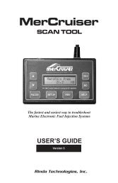
15.5.1 Disassembly of bearings with cylindrical bores<br />
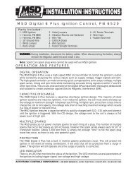
For small type bearings, the pullers shown in Fig. 15.15<br />
a) <strong>and</strong> b) or the press method shown in Fig. 15.16 can be<br />
used for disassembly. When used properly, these<br />
methods can improve disassembly efficiency <strong>and</strong> prevent<br />
damage to bearings.<br />
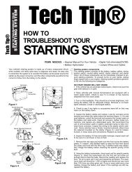
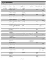
To facilitate disassembly procedures, attention should<br />
be given to planning the designs of shafts <strong>and</strong> housings,<br />
such as providing extraction grooves on the shaft <strong>and</strong><br />
housing for puller claws as shown Figs. 15.17 <strong>and</strong> 15.18.<br />
Threaded bolt holes should also be provided in housings<br />
to facilitate the pressing out of outer rings as shown in<br />
Fig. 15.19.<br />
a<br />
b<br />
Fig. 15.15 Puller disassembly<br />
Fig. 15.16 Press disassembly<br />
Groove<br />
Groove<br />
Fig. 15.17 Extracting grooves<br />
Groove<br />
Fig. 15.18 Extraction groove for outer ring disassembly<br />
A-90