E1400 Servo Controller Installation Guide - LinMot
E1400 Servo Controller Installation Guide - LinMot
E1400 Servo Controller Installation Guide - LinMot

Create successful ePaper yourself
Turn your PDF publications into a flip-book with our unique Google optimized e-Paper software.
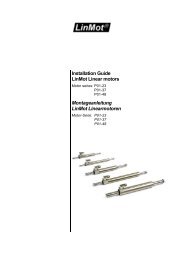
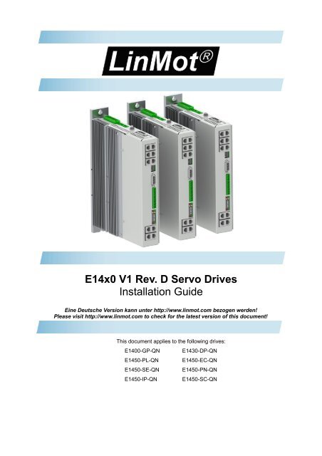
E14x0 V1 Rev. D <strong>Servo</strong> Drives<br />
<strong>Installation</strong> <strong>Guide</strong><br />
Eine Deutsche Version kann unter http://www.linmot.com bezogen werden!<br />
Please visit http://www.linmot.com to check for the latest version of this document!<br />
This document applies to the following drives:<br />
<strong>E1400</strong>-GP-QN E1430-DP-QN<br />
E1450-PL-QN E1450-EC-QN<br />
E1450-SE-QN E1450-PN-QN<br />
E1450-IP-QN E1450-SC-QN
<strong>E1400</strong> V1 Rev. D <strong>Installation</strong> <strong>Guide</strong><br />
© 2013 NTI AG<br />
This work is protected by copyright.<br />
Under the copyright laws, this publication may not be reproduced or transmitted in any form, electronic or mechanical, including<br />
photocopying, recording, microfilm, storing in an information retrieval system, not even for didactical use, or translating, in whole or in<br />
part, without the prior written consent of NTI AG.<br />
<strong>LinMot</strong>® is a registered trademark of NTI AG.<br />
The information in this documentation reflects the stage of development at the time of press and is therefore without obligation.<br />
NTI AG reserves itself the right to make changes at any time and without notice to reflect further technical advance or product<br />
improvement.<br />
Document version 5.0.2 / FM, December 2013<br />
Page 2/24 www.<strong>LinMot</strong>.com NTI AG / <strong>LinMot</strong> ®
<strong>E1400</strong> V1 Rev. D <strong>Installation</strong> <strong>Guide</strong><br />
Table of Content<br />
1 Important Safety Instructions.........................................................................................4<br />
2 System Overview.............................................................................................................6<br />
3 Functionality and Interfaces...........................................................................................7<br />
4 IP Address Selection.......................................................................................................7<br />
5 Power Supply and Grounding........................................................................................8<br />
6 Description of the connectors / Interfaces....................................................................9<br />
6.1 X1-V1 Rev. D..............................................................................................................9<br />
6.2 X30-V1 Rev. D............................................................................................................9<br />
6.3 X2-V1 Rev. D..............................................................................................................9<br />
6.4 X31-X32....................................................................................................................10<br />
6.5 X3-V2........................................................................................................................10<br />
6.6 X4 .............................................................................................................................11<br />
6.7 X7 - X8......................................................................................................................12<br />
6.8 X9..............................................................................................................................12<br />
6.9 X10 - X11..................................................................................................................13<br />
6.10 X13..........................................................................................................................13<br />
6.11 X15 - X16................................................................................................................14<br />
6.12 X17 - X18................................................................................................................14<br />
6.13 X19..........................................................................................................................14<br />
6.14 X20..........................................................................................................................15<br />
6.15 X29..........................................................................................................................15<br />
6.16 S5............................................................................................................................15<br />
6.17 LEDs.......................................................................................................................16<br />
6.18 RT BUS LEDs.........................................................................................................16<br />
6.19 S1 - S2....................................................................................................................16<br />
7 Error Codes....................................................................................................................17<br />
8 Safety Wiring..................................................................................................................18<br />
9 Physical Dimensions.....................................................................................................19<br />
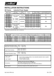
10 Power Supply Requirements......................................................................................20<br />
11 Regeneration of Power / Regeneration Resistor......................................................20<br />
12 Ordering Information...................................................................................................21<br />
13 International Certifications.........................................................................................21<br />
14 Declaration of Conformity CE-Marking......................................................................22<br />
15 Contact Addresses......................................................................................................24<br />
NTI AG / <strong>LinMot</strong> ® www.<strong>LinMot</strong>.com Page 3/24
<strong>E1400</strong> V1 Rev. D <strong>Installation</strong> <strong>Guide</strong><br />
1 Important Safety Instructions<br />
For your personal safety<br />
Disregarding the following safety measures can lead to severe injury to persons and<br />
damage to material:<br />
• Only use the product as directed.<br />
• Never commission the product in the event of visible damage.<br />
• Never commission the product before assembly has been completed.<br />
• Do not carry out any technical changes on the product.<br />
• Only use the accessories approved for the product.<br />
• Only use original spare parts from <strong>LinMot</strong>.<br />
• Observe all regulations for the prevention of accidents, directives and laws applicable on site.<br />
• Transport, installation, commissioning and maintenance work must only be carried out by qualified<br />
personnel.<br />
• Observe IEC 364 and CENELEC HD 384 or DIN VDE 0100 and IEC report 664 or<br />
DIN VDE 0110 and all national regulations for the prevention of accidents.<br />
• According to the basic safety information, qualified, skilled personnel are persons who are<br />
familiar with the assembly, installation, commissioning, and operation of the product and who<br />
have the qualifications necessary for their occupation.<br />
• Observe all specifications in this documentation.<br />
• This is the condition for safe and trouble−free operation and the achievement of the specified<br />
product features.<br />
• The procedural notes and circuit details described in this documentation are only proposals.<br />
It is up to the user to check whether they can be transferred to the particular applications.<br />
NTI AG / <strong>LinMot</strong> does not accept any liability for the suitability of the procedures and circuit<br />
proposals described.<br />
• <strong>LinMot</strong> servo drives and the accessory components can include live and moving parts (depending on<br />
their type of protection) during operation. Surfaces can be hot.<br />
• Non−authorized removal of the required cover, inappropriate use, incorrect installation or<br />
operation create the risk of severe injury to persons or damage to material assets.<br />
• For more information, please see the documentation.<br />
• High amounts of energy are produced in the drive. Therefore it is required to wear personal<br />
protective equipment (body protection, headgear, eye protection, hand guard).<br />
Application as directed<br />
• drives are components which are designed for installation in electrical systems or machines. They<br />
are not to be used as domestic appliances, but only for industrial purposes according to EN<br />
61000−3−2.<br />
• When drives are installed into machines, commissioning (i.e. starting of the operation as directed) is<br />
prohibited until it is proven that the machine complies with the regulations of the EC Directive<br />
98/37/EC (Machinery Directive); EN 60204 must be observed.<br />
• Commissioning (i.e. starting of the operation as directed) is only allowed when there is compliance<br />
with the EMC Directive (2004/108/EC).<br />
• The technical data and supply conditions can be obtained from the nameplate and the<br />
documentation. They must be strictly observed.<br />
Transport, storage<br />
• Please observe the notes on transport, storage, and appropriate handling.<br />
• Observe the climatic conditions according to the technical data.<br />
Page 4/24 www.<strong>LinMot</strong>.com NTI AG / <strong>LinMot</strong> ®
<strong>E1400</strong> V1 Rev. D <strong>Installation</strong> <strong>Guide</strong><br />
<strong>Installation</strong><br />
• The drives must be installed and cooled according to the instructions given in the corresponding<br />
documentation.<br />
• The ambient air must not exceed degree of pollution 2 according to EN 61800−5−1.<br />
• Ensure proper handling and avoid excessive mechanical stress. Do not bend any components and<br />
do not change any insulation distances during transport or handling. Do not touch any electronic<br />
components and contacts.<br />
• drives contain electrostatic sensitive devices which can easily be damaged by inappropriate<br />
handling. Do not damage or destroy any electrical components since this might endanger your<br />
health!<br />
Electrical connection<br />
• When working on live drives, observe the applicable national regulations for the prevention of<br />
accidents.<br />
• The electrical installation must be carried out according to the appropriate regulations (e.g. cable<br />
cross−sections, fuses, PE connection). Additional information can be obtained from the<br />
documentation.<br />
• This product can cause high-frequency interferences in non industrial environments<br />
which can require measures for interference suppression.<br />
Operation<br />
• If necessary, systems including drives must be equipped with additional monitoring and protection<br />
devices according to the valid safety regulations (e.g. law on technical equipment, regulations for the<br />
prevention of accidents). The drives can be adapted to your application. Please observe the<br />
corresponding information given in the documentation.<br />
• After the drive has been disconnected from the supply voltage, all live components and power<br />
connections must not be touched immediately because capacitors can still be charged. Please<br />
observe the corresponding stickers on the drive. All protection covers and doors must be shut during<br />
operation.<br />
Protection of persons<br />
• Before working on the drive, check that no voltage is applied to the power terminals:<br />
• The power terminals U, V, W, DC+, DC-, RR+, and RR- remain live for at<br />
least 5 minutes after disconnecting from mains.<br />
• The power terminals L1, L2, L3; U, V, W, DC+, DC-, RR+ and RR- remain<br />
live when the motor is stopped.<br />
• The leakage current to earth (PE) is >3.5 mA. According to EN 50178 a fixed<br />
installation is required and a double PE connection is required.<br />
• The heat sink of the drive has an operating temperature of > 80 °C: Contact with the<br />
heat sink results in burns.<br />
NTI AG / <strong>LinMot</strong> ® www.<strong>LinMot</strong>.com Page 5/24
<strong>E1400</strong> V1 Rev. D <strong>Installation</strong> <strong>Guide</strong><br />
2 System Overview<br />
Typical <strong>Servo</strong> System E14x0-XX: <strong>Servo</strong> Drive, Motor and Power Supply.<br />
Page 6/24 www.<strong>LinMot</strong>.com NTI AG / <strong>LinMot</strong> ®
<strong>E1400</strong> V1 Rev. D <strong>Installation</strong> <strong>Guide</strong><br />
3 Functionality and Interfaces<br />
E1450-PL-QN<br />
E1450-PN-QN<br />
E1450-SC-QN<br />
E1450-IP-QN<br />
E1450-EC-QN<br />
E1450-SE-QN<br />
E1430-DP-QN<br />
<strong>E1400</strong>-GP-QN<br />
Supply Voltage<br />
Motor Supply 3x400 VAC / 3x480 VAC ● ● ● ● ● ● ● ●<br />
Logic Supply 24VDC (22...26VDC) ● ● ● ● ● ● ● ●<br />
Motor Phase Current (preliminary)<br />
28A rms peak ● ● ● ● ● ● ● ●<br />
4 A rms continuous (without forced cooling) ● ● ● ● ● ● ● ●<br />
12 A rms continuous (with fan EV01-<strong>E1400</strong>) ● ● ● ● ● ● ● ●<br />
18 A rms continuous (cold plate 20°C) ● ● ● ● ● ● ● ●<br />
Controllable Motors<br />
<strong>LinMot</strong> P10-70x…(Motor Link C) ● ● ● ● ● ● ● ●<br />
Selected motors (contact support) ● ● ● ● ● ● ● ●<br />
Command Interface<br />
CANopen ● ● ● ● ● ● ● ●<br />
LinRS ● ● ● ● ● ● ● ●<br />
POWERLINK<br />
●<br />
PROFINET<br />
●<br />
SERCOS III<br />
●<br />
ETHERNET IP<br />
●<br />
ETHERCAT ● ●<br />
SERCOS over ETHERCAT ● ●<br />
PROFIBUS-DP<br />
●<br />
Programmable Motion Profiles (Curves)<br />
Up to 100 Motion Profiles ● ● ● ● ● ● ● ●<br />
Programmable Command Table<br />
Command Table with up to 255 entries ● ● ● ● ● ● ● ●<br />
External Position Sensor<br />
Incremental (RS422 up to 25 M counts/s) ● ● ● ● ● ● ● ●<br />
SinCos (1Vpp differential) ● ● ● ● ● ● ● ●<br />
Absolute (BiSS) ● ● ● ● ● ● ● ●<br />
Synchronisation<br />
Master Encoder In/Out<br />
(RS422 up to 25 M counts/s)<br />
● ● ● ● ● ● ● ●<br />
Configuration Interface<br />
RS232 ● ● ● ● ● ● ● ●<br />
Ethernet 10/100 Mbit/s<br />
(2-Port Switch integrated)<br />
● ● ● ● ● ● ● ●<br />
4 IP Address Selection<br />
The default mode for acquiring an IP address is via DHCP. If no servers respond on<br />
the connected network, the drive switches to the IPv4 Link-Local addressing<br />
scheme (also known as APIPA on Windows systems). This way the drive<br />
automatically assigns itself an address within the range of 169.254.0.1 through<br />
169.254.255.254 (Subnet Mask 255.255.0.0).<br />
Please note that this process can take up to a minute until a valid address is<br />
assigned to the drive.<br />
NTI AG / <strong>LinMot</strong> ® www.<strong>LinMot</strong>.com Page 7/24
<strong>E1400</strong> V1 Rev. D <strong>Installation</strong> <strong>Guide</strong><br />
5 Power Supply and Grounding<br />
In order to assure a safe and error free operation, and to avoid severe<br />
damage to system components, all system components must be well<br />
grounded to protective earth PE. This includes both <strong>LinMot</strong> and all<br />
other control system components on the same ground bus.<br />
The leakage current to earth (PE) is >3.5 mA. According to EN 50178 a<br />
fixed installation is required and a double PE connection is required.<br />
One PE connection is on X30, the second one is an M5 bolt on top of<br />
the housing.<br />
Each system component should be tied directly to the ground bus (star<br />
pattern), rather than daisy chaining from component to component.<br />
(<strong>LinMot</strong> motors are properly grounded through their power cables when<br />
connected to <strong>LinMot</strong> drives.)<br />
Page 8/24 www.<strong>LinMot</strong>.com NTI AG / <strong>LinMot</strong> ®
<strong>E1400</strong> V1 Rev. D <strong>Installation</strong> <strong>Guide</strong><br />
6 Description of the connectors / Interfaces<br />
6.1 X1-V1 Rev. D<br />
X1<br />
DC Busbar/ Regeneration Resistor<br />
DC+: DC busbar +<br />
DC-: DC busbar -<br />
RR+: Positive connection for Regeneration Resistor<br />
RR-: Negative connection for Regeneration Resistor<br />
Screw Terminals:<br />
- Tightening torque: 0.7 - 0.8 Nm<br />
- Use a cross-head screw driver (PH1)<br />
- Use 60/75°C copper conductors only<br />
- Conductor cross-section: 0.25 – 4 mm 2 (depends on Motor current) / AWG 24 -12<br />
- Stripping length 10mm<br />
6.2 X30-V1 Rev. D<br />
X30<br />
Motor Supply Mains<br />
L1 – L3:<br />
PE:<br />
3x400 / 3x480VAC 50/60 Hz<br />
PE, Protective Earth<br />
Screw Terminals:<br />
- Tightening torque: 0.7 - 0.8 Nm<br />
- Use a cross-head screw driver (PH1)<br />
- Use 60/75°C copper conductors only<br />
- Conductor cross-section: 2.5 – 4 mm 2 (depends on Motor current) / AWG 24 -12<br />
- Stripping length 10mm<br />
6.3 X2-V1 Rev. D<br />
X2<br />
Motor Phases<br />
PE: Protective Earth and Cable Shield<br />
W: Motor Phase W<br />
V: Motor Phase V<br />
U: Motor Phase U<br />
KTY+: Temperature Sensor KTY+<br />
KTY-: Temperature Sensor KTY-<br />
Screw Terminals:<br />
- Tightening torque: 0.7 - 0.8 Nm<br />
- Use a cross-head screw driver (PH1)<br />
- Use 60/75°C copper conductors only<br />
- Conductor cross-section: 0.25 – 4 mm 2 (depends on Motor current) / AWG 24 -12<br />
- Stripping length 10mm<br />
Attention:<br />
The type of connector and pin assignment on V1 Rev. D and V2 drives<br />
is different from V1 (Rev. A-C) drives (different coding)!<br />
NTI AG / <strong>LinMot</strong> ® www.<strong>LinMot</strong>.com Page 9/24
<strong>E1400</strong> V1 Rev. D <strong>Installation</strong> <strong>Guide</strong><br />
6.4 X31-X32<br />
X31-X32<br />
Motor Brake and Motor Brake Supply<br />
X32: Brake-<br />
Brake+<br />
X31: Brake Supply GND<br />
Brake Supply +24VDC<br />
6.5 X3-V2<br />
X3<br />
Motor Encoder (Motor Link C / BISS)<br />
8<br />
7<br />
6<br />
5<br />
4<br />
3<br />
2<br />
1<br />
case<br />
15<br />
14<br />
13<br />
12<br />
11<br />
10<br />
9<br />
Motor Link C -<br />
Motor Link C +<br />
Clock -<br />
Clock +<br />
Data -<br />
Data +<br />
GND<br />
Temp<br />
GND Sense<br />
+5V Sense<br />
Cos-<br />
Cos+<br />
Sin-<br />
Sin+<br />
+5V<br />
shield<br />
DSUB-15 (m)<br />
Motor Link C is a high speed serial communication protocol to the motor encoder.<br />
Page 10/24 www.<strong>LinMot</strong>.com NTI AG / <strong>LinMot</strong> ®
<strong>E1400</strong> V1 Rev. D <strong>Installation</strong> <strong>Guide</strong><br />
6.6 X4<br />
X4<br />
Logig Supply / IO Connection<br />
16<br />
15<br />
14<br />
13<br />
12<br />
11<br />
10<br />
9<br />
8<br />
7<br />
6<br />
5<br />
4<br />
3<br />
2<br />
1<br />
Ksr +<br />
Ksr -<br />
Ksr f+<br />
Ksr f-<br />
Input<br />
SVE<br />
Quickstop<br />
Input<br />
I/O X4.10<br />
I/O X4.9<br />
I/O X4.8<br />
I/O X4.7<br />
I/O X4.6<br />
I/O X4.5<br />
I/O X4.4<br />
I/O X4.3<br />
+24VDC Supply<br />
GND Supply<br />
Safety Relay Input positive<br />
Safety Relay Input negative<br />
Safety Relay feedback positive<br />
Safety Relay feedback negative<br />
Power Stage Enable (HW Enable)<br />
Quickstop, PTC2 Input<br />
Configurable IO, PTC1 Input<br />
Configurable IO<br />
Configurable IO<br />
Configurable IO<br />
Configurable IO, Trigger Input<br />
Configurable IO<br />
Configurable IO, Analog Input (configurable as high imp. Input)<br />
Configurable IO<br />
Logic Supply 22-26 VDC<br />
Ground<br />
Screw terminals Inputs (X4.3 .. X4.12): 24V / 5mA (Low Level: –0.5 to 5VDC, High Level: 15 to 30VDC)<br />
Outputs (X4.4 .. X4.10): 24V / max.100mA, Peak 370mA (will shut down if exceeded)<br />
Output (X4.3):<br />
24V / max.1.0A<br />
To enable the power stage the input SVE (X4.12) and the integrated safety relay Ksr (X4.13 – X4.16) must<br />
be correctly wired. Please refer to chapter 8 Safety Wiring.<br />
Input X4.12: SVE (Safety Voltage Enable) must be high for enabling the power stage. If it goes low for<br />
more than 0.5ms the PWM generation of the power stage is disabled by hardware.<br />
To disable the internal safety features, connect X4.16 and X4.12 to +24VDC and X4.15 to GND.<br />
Supply 24V / type. 500mA / max. 2.5A (if all outputs “on” with max. load.)<br />
- Tightening torque: min 0.22Nm<br />
- Screw thread: M2<br />
- Use 60/75°C copper conductors only<br />
- Conductor cross-section max. 1.5mm 2<br />
- Internal Fuse (F2): 3AT (slow blow, Schurter OMT125, 3404.0118.xx, UL File Number: E41599)<br />
CAUTION: For continued protection against risk of fire, replace only with same type and rating of fuse.<br />
NTI AG / <strong>LinMot</strong> ® www.<strong>LinMot</strong>.com Page 11/24
<strong>E1400</strong> V1 Rev. D <strong>Installation</strong> <strong>Guide</strong><br />
6.7 X7 - X8<br />
X7 - X8<br />
CMD (RS485/CAN)<br />
1<br />
2<br />
X3<br />
4<br />
5<br />
6<br />
7<br />
8<br />
case<br />
RS485_Rx+<br />
RS485_Rx-<br />
RS485_Tx+<br />
GND<br />
GND<br />
RS485_Tx-<br />
CAN_H<br />
CAN_L<br />
Shield<br />
A<br />
B<br />
Y<br />
Z<br />
RJ-45<br />
Use twisted pair (1-2, 3-6, 4-5, 7-8) cable for wiring.<br />
The built in RS485 and CAN terminations can be activated by S5.2 and S5.3.<br />
X7 is internally connected to X8 (1:1 connection)<br />
6.8 X9<br />
X9<br />
PROFIBUS DP (only available on E1430-DP-QN)<br />
1<br />
2<br />
3<br />
4<br />
5<br />
6<br />
7<br />
8<br />
9<br />
case<br />
Not connected<br />
+5V (isolated)<br />
Not connected<br />
Not connected<br />
RxD/TxD-P<br />
RxD/TxD-N<br />
CNTR-P<br />
Not connected<br />
GND<br />
(isolated)<br />
Shield<br />
DSUB-9 (f)<br />
Max. Baud rate: 12Mbaud<br />
Page 12/24 www.<strong>LinMot</strong>.com NTI AG / <strong>LinMot</strong> ®
<strong>E1400</strong> V1 Rev. D <strong>Installation</strong> <strong>Guide</strong><br />
6.9 X10 - X11<br />
X10 - X11<br />
Master Encoder IN (X10) / Master Encoder OUT (X11)<br />
Incremental:<br />
Step/Direction:<br />
EIA/TIA 568A colors:<br />
1<br />
2<br />
3<br />
4<br />
5<br />
6<br />
7<br />
8<br />
case<br />
A+ Step+<br />
A- Step-<br />
B+ Direction+<br />
Z+ Zero+<br />
Z- Zero-<br />
B- Direction-<br />
CAN_H<br />
CAN_H<br />
CAN_L<br />
CAN_L<br />
Shield<br />
Shield<br />
Green/White<br />
Green<br />
Orange/White<br />
Blue<br />
Blue/White<br />
Orange<br />
Brown/White<br />
Brown<br />
RJ-45<br />
Use twisted pair (1-2, 3-6, 4-5, 7-8) cable for wiring.<br />
Master Encoder Inputs:<br />
Master Encoder Outputs:<br />
Differential RS422, max. 25 M counts/s, 40ns edge separation<br />
Amplified RS422 differential signals from Master Encoder IN (X10)<br />
The CAN bus can be terminated with S5.4.<br />
All devices, which are connected to X10/X11 must be referenced to the same ground.<br />
6.10 X13<br />
X13<br />
External Position Sensor Differential Hall Switches<br />
1<br />
2<br />
3<br />
4<br />
5<br />
6<br />
7<br />
8<br />
case<br />
9<br />
10<br />
11<br />
12<br />
13<br />
14<br />
15<br />
+5V DC<br />
A-<br />
B-<br />
Z-<br />
GND<br />
U-<br />
V-<br />
W-<br />
Shield<br />
A+<br />
B+<br />
Z+<br />
Encoder Alarm<br />
U+<br />
V+<br />
W+<br />
DSUB-15 (f)<br />
Position Encoder Inputs (RS422):<br />
Max Input Frequency: 25 M counts/s with quadrature decoding, 40ns edge separation<br />
Encoder Simulation Outputs (RS422):<br />
Max Output Frequency: 25 M counts/s with quadrature decoding, 40ns edge separation<br />
Differential Hall Switch Inputs (RS422):<br />
Input Frequency:
<strong>E1400</strong> V1 Rev. D <strong>Installation</strong> <strong>Guide</strong><br />
6.11 X15 - X16<br />
X15 - X16<br />
Config Ethernet 10/100 Mbit/s<br />
X15<br />
X16<br />
Internal 2-Port 10BASE-T and 100BASE-TX Ethernet Switch with Auto MDIX.<br />
LEDs on the lower side of the device indicate “Link/Activity” per port, the upper ones<br />
are not used.<br />
RJ-45<br />
6.12 X17 - X18<br />
X17 - X18<br />
RealTime Ethernet 10/100 Mbit/s<br />
X17 RT ETH In<br />
Specification depends on RT-Bus Type. Please refer to according documentation.<br />
X18 RT ETH Out<br />
RJ-45<br />
6.13 X19<br />
X19<br />
System<br />
1<br />
2<br />
3<br />
4<br />
5<br />
6<br />
7<br />
8<br />
case<br />
Do not connect<br />
Do not connect<br />
RS232 Rx<br />
GND<br />
GND<br />
RS232 Tx<br />
Do not connect<br />
Do not connect<br />
Shield<br />
RJ-45<br />
Use adapter cable AC01-RJ45/Df-2.5-RS1 (Art.-No. 0150-2143) for configuration over RS232.<br />
Page 14/24 www.<strong>LinMot</strong>.com NTI AG / <strong>LinMot</strong> ®
<strong>E1400</strong> V1 Rev. D <strong>Installation</strong> <strong>Guide</strong><br />
6.14 X20<br />
X20<br />
Analog In (+-10V Differential Analog Input)<br />
1<br />
2<br />
3<br />
4<br />
5<br />
6<br />
7<br />
8<br />
case<br />
Do not connect<br />
Do not connect<br />
Analog In -<br />
GND<br />
GND<br />
Analog In +<br />
Do not connect<br />
Do not connect<br />
Shield<br />
RJ-45<br />
6.15 X29<br />
X29<br />
Connector for Fan Option<br />
Connector for the external fan option (Art. Nr. 0150-xxxx).<br />
Output: 24 VDC / 0.4 A (Short circuit protected, current monitored)<br />
Stripping length: 8mm<br />
Conductor cross section: 0.2 – 1.5 mm 2 (AWG 24 - 16)<br />
6.16 S5<br />
S5<br />
Bus Termination / AnaIn2 Pull Down<br />
S5<br />
Switch 6: Override Configuration Ethernet to DHCP<br />
Switch 5: Bootstrap: Must be off for normal operation<br />
Switch 4: CAN termination on ME (120R between pin 7 and 8 on X10/X11) on/off<br />
Switch 3: CAN termination on CMD (120R between pin 7 and 8 on X7/X8) on/off<br />
Switch 2: Termination resistor for RS485 on CMD (120R between pin 1 and 2 on X7/X8) on/off<br />
Switch 1: AnIn2 pull down (4k7 Pull down on X4.4). Set to ON, if X4.4 is used as digital output.<br />
Factory setting: all switches “on” except S5.5 (Bootstrap) and S5.6 (Override to DHCP)<br />
NTI AG / <strong>LinMot</strong> ® www.<strong>LinMot</strong>.com Page 15/24
<strong>E1400</strong> V1 Rev. D <strong>Installation</strong> <strong>Guide</strong><br />
6.17 LEDs<br />
LEDs<br />
State Display<br />
Green<br />
Yellow<br />
Yellow<br />
Red<br />
24V Logic Supply OK<br />
Motor Enabled / Error Code Low Nibble<br />
Warning / Error Code High Nibble<br />
Error<br />
6.18 RT BUS LEDs<br />
RT Bus LEDs<br />
RT Bus State Display<br />
Green<br />
Red<br />
OK<br />
Error<br />
The use of these LEDs depends on the type of fieldbus which is used. Please see the corresponding<br />
manual for further information.<br />
6.19 S1 - S2<br />
S1 - S2<br />
Address Selectors<br />
S1 (5..8)<br />
Bus ID High (0 … F). Bit 5 is the LSB, bit 8 the MSB.<br />
S2 (1..4)<br />
Bus ID Low (0 … F). Bit 1 is the LSB, bit 4 the MSB.<br />
The use of these switches depends on the type of fieldbus which is used. Please see the corresponding<br />
manual for further information.<br />
Page 16/24 www.<strong>LinMot</strong>.com NTI AG / <strong>LinMot</strong> ®
<strong>E1400</strong> V1 Rev. D <strong>Installation</strong> <strong>Guide</strong><br />
7 Error Codes<br />
Error Codes<br />
Error Warn EN Description<br />
Off Warning Operation<br />
Enabled<br />
Normal Operation:<br />
Warnings and operation enabled are displayed.<br />
On<br />
● ~2Hz<br />
0..15 x<br />
Error Code<br />
High Nibble<br />
● ~2Hz<br />
0..15 x<br />
Error Code<br />
Low Nibble<br />
Error:<br />
The error code is shown by a blink code with “WARN” and “EN”.<br />
The error byte is divided into low and high nibble (= 4 bit).<br />
”WARN” and “EN” are blinking together.<br />
The error can be acknowledged.<br />
(e.g.: WARN blinks 3x, EN blinks 2x; Error Code = 32h)<br />
● ~2Hz<br />
● ~2Hz<br />
0..15 x<br />
Error Code<br />
High Nibble<br />
● ~2Hz<br />
0..15 x<br />
Error Code<br />
Low Nibble<br />
Fatal Error:<br />
The error code is shown by a blink code with “WARN” and “EN”.<br />
The error byte is divided into low and high nibble.<br />
”WARN” and “EN” are blinking together.<br />
Fatal errors can only be acknowledged by a reset or power cycle.<br />
(e.g.: WARN blinks 3x, EN blinks 2x; Error Code = 32h)<br />
● ~4Hz<br />
● ~2Hz<br />
0..15 x<br />
Error Code<br />
High Nibble<br />
● ~2Hz<br />
0..15 x<br />
Error Code<br />
Low Nibble<br />
System Error:<br />
Please reinstall firmware or contact support.<br />
● ~0.5Hz ● ~0.5Hz On Signal Supply 24V too low:<br />
The error and warn LEDs blink alternating if the signal supply +24V (X4.2) is<br />
less than 18VDC.<br />
The meaning of the error codes can be found in the<br />
Usermanual_MotionCtrl_Software_SG5 and the user manual of the installed<br />
interface software. These documents are provided together with <strong>LinMot</strong>-Talk<br />
configuration software and can be downloaded from www.linmot.com.<br />
NTI AG / <strong>LinMot</strong> ® www.<strong>LinMot</strong>.com Page 17/24
<strong>E1400</strong> V1 Rev. D <strong>Installation</strong> <strong>Guide</strong><br />
8 Safety Wiring<br />
The <strong>E1400</strong> Drive has internal safety functions:<br />
• SVE (Safety Voltage enable): Fast reacting inhibition of power pulses.<br />
• Safety relay Ksr, which supports the 15 V for the IGBT drivers. It has two<br />
feedback contacts.<br />
Safety Relay Ksr<br />
Nominal voltage<br />
24 VDC<br />
Min. pick-up voltage at 20°C ≤ 16.8V<br />
Drop-out voltage at 20°C<br />
≥ 2.4 V<br />
Coil resistance at 20°C 2'100 Ω ± 10%<br />
Type<br />
EN 50205, type A<br />
Page 18/24 www.<strong>LinMot</strong>.com NTI AG / <strong>LinMot</strong> ®
<strong>E1400</strong> V1 Rev. D <strong>Installation</strong> <strong>Guide</strong><br />
9 Physical Dimensions<br />
<strong>E1400</strong> Series single axis drive<br />
Width mm (in) 50 (2)<br />
Height mm (in) 300 (11.8)<br />
Height with fixings mm (in) 345 (13.6)<br />
Depth mm (in) 221.5 (8.8)<br />
Weight kg (lb) 4.3 (9.5)<br />
Mounting<br />
2 x M5<br />
Case IP 20<br />
Storage Temperature °C -25…40<br />
Transport Temperature °C -25…70<br />
Operating Temperature °C 0…40 at rated data<br />
Relative humidity<br />
Pollution<br />
IEC/EN<br />
60664-1<br />
40...50 with power derating<br />
95% (non-condensing)<br />
Pollution degree 2<br />
Site altitude m amsl to be defined<br />
Max. Case Temperature °C 90<br />
Max. Power Dissipation W 100<br />
Mounting place<br />
Mounting position<br />
Distance between drives<br />
(passive convection cooling)<br />
Distance between drives (with fan option<br />
EV01-<strong>E1400</strong>)<br />
Distance between drives (cold plate<br />
cooling)<br />
mm (in)<br />
mm (in)<br />
mm (in)<br />
In the control cabinet<br />
vertical<br />
≥ 35 (1.4) left (heat sink side)<br />
≥ 5 (0.2) right<br />
≥ 200 (8) top / bottom<br />
≥ 40 (1.6) left (heat sink side)<br />
≥ 5 (0.2) right<br />
≥ 200 (8) top / bottom<br />
≥ 0 (0) left/right<br />
≥ 200 (8) top / bottom<br />
NTI AG / <strong>LinMot</strong> ® www.<strong>LinMot</strong>.com Page 19/24
<strong>E1400</strong> V1 Rev. D <strong>Installation</strong> <strong>Guide</strong><br />
10 Power Supply Requirements<br />
Motor Power Supply<br />
Direct AC mains connection: 3/PE AC 400V (±10%) / 50-60Hz / TN System<br />
3/PE AC 480V (±10%) / 50-60Hz / TN System<br />
Only 3-phase supply is supported! The mains must be a symmetrical<br />
four-wire system with grounded neutral.<br />
DC Supply (for example 72VDC) for initial test setups can be supplied through<br />
the 3-phase supply connector.<br />
Use a circuit breaker C20 and conductor cross section of 2.5mm 2 for mains<br />
connections!<br />
The <strong>LinMot</strong> line filter NF01-FN258-16-07 must be connected near the supply<br />
connector of the drive to conform to the EMC requirements of CE.<br />
Current consumption:<br />
Startup Current: Soft start over 50 Ohm charge resistor.<br />
Signal Power Supply<br />
The logic supply needs a regulated power supply of a nominal voltage of 24 VDC.<br />
The voltage must be between 22 and 26 VDC.<br />
Current consumption:<br />
min. 0.5A<br />
typ. 1.5A<br />
max. 2.5A<br />
(no load on the outputs)<br />
(all 10 outputs “on” with 100mA load and /Break with no load)<br />
(all 10 outputs “on” with 100mA load and /Break with 1A load)<br />
11 Regeneration of Power / Regeneration Resistor<br />
There are two possibilities to deal with power regeneration:<br />
Option A:<br />
Option B:<br />
DC Link coupling or additional Capacitors<br />
Install a regeneration resistor to X1 (RR+ and RR-). The threshold<br />
value of the voltage depends on the used motor voltage power supply.<br />
The max. threshold value must not exceed 780 VDC.<br />
Item Description Art. No.<br />
Regeneration Resistor RR01-68/100 (68 Ohm, 100 W) 0150-3373<br />
Page 20/24 www.<strong>LinMot</strong>.com NTI AG / <strong>LinMot</strong> ®
<strong>E1400</strong> V1 Rev. D <strong>Installation</strong> <strong>Guide</strong><br />
12 Ordering Information<br />
Item Description Art. Nr.<br />
E1450-PL-QN POWERLINK Drive (3x400/28A) 0150-1791<br />
E1450-PN-QN PROFINET Drive (3x400/28A) 0150-1783<br />
E1450-EC-QN ETHERCAT Drive (3x400/28A) 0150-1784<br />
E1450-SC-QN SERCOS III Drive (3x400/28A) 0150-1785<br />
E1450-IP-QN ETHERNET IP Drive (3x400/28A) 0150-1782<br />
E1430-DP-QN PROFIBUS-DP Drive (3x400/28A) 0150-1786<br />
<strong>E1400</strong>-GP-QN GENERAL PURPOSE Drive (3x400/28A) 0150-1779<br />
E1450-SE-QN SERCOS over ETHERCAT Drive (3x400/28A) 0150-1899<br />
RS232 PC config. Cable<br />
2.5m<br />
For E1200 / <strong>E1400</strong><br />
0150-2143<br />
RR01-68/100 Regeneration resistor (68R, 100W, 1000V) 0150-3373<br />
EV01-<strong>E1400</strong> Fan Option for <strong>E1400</strong> 0150-5055<br />
NF01-FN258-16-07 3-phase line filter for <strong>E1400</strong> 0150-2359<br />
13 International Certifications<br />
Certifications<br />
Europe<br />
See chapter “14 Declaration of Conformity CE-Marking“<br />
UL<br />
UL508C pending<br />
NTI AG / <strong>LinMot</strong> ® www.<strong>LinMot</strong>.com Page 21/24
<strong>E1400</strong> V1 Rev. D <strong>Installation</strong> <strong>Guide</strong><br />
14 Declaration of Conformity CE-Marking<br />
Manufacturer: NTI AG / <strong>LinMot</strong> ®<br />
Products:<br />
Haerdlistrasse 15<br />
8957 Spreitenbach<br />
Switzerland<br />
Tel.: +41 (0)56 419 91 91<br />
Fax: +41 (0)56 419 91 92<br />
<strong>LinMot</strong> ® drives<br />
Type Art.-No. Type Art-No. Type Art.-No.<br />
E1450-PL-QN 0150-1791 E1450-IP-QN 0150-1782 E1450-EC-QN 0150-1784<br />
E1450-PN-QN 0150-1783 E1430-DP-QN 0150-1786 E1450-SC-QN 0150-1785<br />
<strong>E1400</strong>-GP-QN 0150-1779 E1450-SE-QN 0150-1899<br />
The product must be mounted and used in strict accordance with the installation instructions<br />
contained within the installation guide, a copy of which may be obtained from NTI Ltd.<br />
I declare that as the authorized representative, the above information in relation to the<br />
supply/manufacture of this product is in conformity with the stated standards and other related<br />
documents in compliance with the protection requirements of the Electromagnetic Compatibility<br />
(EMC) Directive 2004/108/EC and Safety tests according to the 2006/95/EC harmonized standard<br />
EN 50371: 2002.<br />
Standards Complied with:<br />
EN 61000-6-2: 2005<br />
Immunity for industrial environments<br />
EN 61000-4-2 Class B and FS Electrostatic discharge immunity (ESD)<br />
EN 61000-4-3 Class A and FS Radiated electromagnetic field immunity<br />
EN 61000-4-4 Class B and FS Fast transients / burst immunity (EFT)<br />
EN 61000-4-5 Class B and FS Slow transients immunity (Surge)<br />
EN 61000-4-6 Class A and FS Conducted radio frequency immunity<br />
EN 61000-4-8 Class A and FS Power frequency magnetic field immunity<br />
EN 61326-3-1 FS EMC immunity (functional safety)<br />
EN 61000-6-4: 2007<br />
Emission for industrial environments<br />
EN 55022 Class A Stationary interference voltage AC mains<br />
EN55022 Class A Stat. Asym. Interference current on Telco lines<br />
EN 55022 Class A Radiated Emission<br />
EN 61326-3-1:2008<br />
EN 50371<br />
EN 5022<br />
EN 5011<br />
CISPR 22: 2005<br />
Company: NTI Ltd.<br />
Spreitenbach, May 02, 2012<br />
Functional Safety<br />
Human exposure to electromagnetic fields<br />
Radio disturbance (IT equipment)<br />
Radio disturbance (ISM)<br />
Radio disturbance (IT equimpment)<br />
-----------------------------------------------------------<br />
R. Rohner / CEO NTI AG<br />
Page 22/24 www.<strong>LinMot</strong>.com NTI AG / <strong>LinMot</strong> ®
<strong>E1400</strong> V1 Rev. D <strong>Installation</strong> <strong>Guide</strong><br />
NTI AG / <strong>LinMot</strong> ® www.<strong>LinMot</strong>.com Page 23/24
<strong>E1400</strong> V1 Rev. D <strong>Installation</strong> <strong>Guide</strong><br />
15 Contact Addresses<br />
SWITZERLAND<br />
NTI AG<br />
Haerdlistr. 15<br />
CH-8957 Spreitenbach<br />
Sales and Administration: +41-(0)56-419 91 91<br />
office@linmot.com<br />
Tech. Support: +41-(0)56-544 71 00<br />
support@linmot.com<br />
Tech. Support (Skype) :<br />
skype:support.linmot<br />
Fax: +41-(0)56-419 91 92<br />
Web:<br />
http://www.linmot.com/<br />
USA<br />
<strong>LinMot</strong>, Inc.<br />
204 E Morrissey Dr.<br />
Elkhorn, WI 53121<br />
Sales and Administration: 877-546-3270<br />
262-743-2555<br />
Tech. Support: 877-804-0718<br />
262-743-1284<br />
Fax: 800-463-8708<br />
262-723-6688<br />
E-Mail:<br />
Web:<br />
us-sales@linmot.com<br />
http://www.linmot-usa.com/<br />
Please visit http://www.linmot.com/ to find the distributor closest to you.<br />
Smart solutions are…<br />
Page 24/24 www.<strong>LinMot</strong>.com NTI AG / <strong>LinMot</strong> ®