E1200 Servo Drive Installation Guide - LinMot
E1200 Servo Drive Installation Guide - LinMot
E1200 Servo Drive Installation Guide - LinMot

Create successful ePaper yourself
Turn your PDF publications into a flip-book with our unique Google optimized e-Paper software.
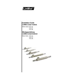
<strong>E1200</strong> <strong>Servo</strong> <strong>Drive</strong><br />
<strong>Installation</strong> <strong>Guide</strong><br />
Eine Deutsche Version kann unter http://www.linmot.com bezogen werden!<br />
Please visit http://www.linmot.com to check for the latest version of this document!<br />
This document applies to the following drives:<br />
<strong>E1200</strong>-GP-UC E1230-DP-UC<br />
E1250-PL-UC E1250-EC-UC<br />
E1250-SE-UC E1250-PN-UC<br />
E1250-IP-UC E1250-SC-UC
<strong>LinMot</strong> <strong>Installation</strong> <strong>Guide</strong><br />
<strong>E1200</strong> <strong>Installation</strong> <strong>Guide</strong><br />
© 2012 NTI AG<br />
This work is protected by copyright.<br />
Under the copyright laws, this publication may not be reproduced or transmitted in any form, electronic or mechanical, including<br />
photocopying, recording, microfilm, storing in an information retrieval system, not even for didactical use, or translating, in whole or in<br />
part, without the prior written consent of NTI AG.<br />
<strong>LinMot</strong>® is a registered trademark of NTI AG.<br />
The information in this documentation reflects the stage of development at the time of press and is therefore without obligation.<br />
NTI AG reserves itself the right to make changes at any time and without notice to reflect further technical advance or product<br />
improvement.<br />
Document version 5.2a/ mk/Ro/FM, December 2013<br />
NTI AG / <strong>LinMot</strong> ® www.<strong>LinMot</strong>.com Page 2/20
<strong>LinMot</strong> <strong>Installation</strong> <strong>Guide</strong><br />
Table of Content<br />
1 Important Safety Notes for <strong>E1200</strong> Series <strong>Drive</strong>s..........................................................4<br />
2 System Overview.............................................................................................................5<br />
3 Functionality and Interfaces...........................................................................................6<br />
4 IP Address Selection.......................................................................................................6<br />
5 Power Supply and Grounding........................................................................................7<br />
6 Description of the connectors / Interfaces....................................................................8<br />
6.1 X1................................................................................................................................8<br />
6.2 X2................................................................................................................................8<br />
6.3 X3................................................................................................................................9<br />
6.4 X4 .............................................................................................................................10<br />
6.5 X7 - X8......................................................................................................................10<br />
6.6 X9..............................................................................................................................11<br />
6.7 X10 - X11..................................................................................................................11<br />
6.8 X13............................................................................................................................12<br />
6.9 X15 - X16..................................................................................................................12<br />
6.10 X17 - X18................................................................................................................13<br />
6.11 X19..........................................................................................................................13<br />
6.12 X20..........................................................................................................................13<br />
6.13 S5............................................................................................................................14<br />
6.14 LEDs.......................................................................................................................14<br />
6.15 RT BUS LEDs.........................................................................................................14<br />
6.16 S1 - S2....................................................................................................................14<br />
7 Error Codes....................................................................................................................15<br />
8 Physical Dimensions.....................................................................................................16<br />
9 Power Supply Requirements........................................................................................17<br />
10 Regeneration of Power / Regeneration Resistor......................................................18<br />
11 Ordering Information...................................................................................................18<br />
12 International Certifications.........................................................................................18<br />
13 Classification of the safety functionality...................................................................19<br />
14 Declaration of Conformity CE-Marking......................................................................19<br />
15 Contact Addresses......................................................................................................20<br />
<strong>E1200</strong> <strong>Installation</strong> <strong>Guide</strong><br />
NTI AG / <strong>LinMot</strong> ® www.<strong>LinMot</strong>.com Page 3/20
<strong>LinMot</strong> <strong>Installation</strong> <strong>Guide</strong><br />
1 Important Safety Notes for <strong>E1200</strong> Series <strong>Drive</strong>s<br />
C A U T I O N !<br />
In order to assure a safe and error free operation, and to avoid<br />
severe damage to system components, all system components<br />
must be directly attached to a single ground bus that is earth or<br />
utility grounded (see chapter 5 Power Supply and Grounding).<br />
Each system component should be tied directly to the ground bus<br />
(star pattern), rather than daisy chaining from component to<br />
component. (<strong>LinMot</strong> motors are properly grounded through their<br />
power cables when connected to <strong>LinMot</strong> drives) (see chapter 5<br />
Power Supply and Grounding).<br />
<strong>E1200</strong> <strong>Installation</strong> <strong>Guide</strong><br />
All connectors must not be connected or disconnected while DC<br />
voltage is present. Do not disconnect system components until all<br />
<strong>LinMot</strong> drive LEDs have turned off. (Capacitors in the power<br />
supply may not fully discharge for several minutes after input<br />
voltage has been disconnected). Failure to observe these<br />
precautions may result in severe damage to electronic<br />
components in <strong>LinMot</strong> motors and/or drives.<br />
Do not switch Power Supply DC Voltage. All power supply<br />
switching and E-Stop breaks should be done to the AC supply<br />
voltage of the power supply.<br />
Do not connect or disconnect the motors from drives with voltage<br />
present. Wait to connect or disconnect motors until all <strong>LinMot</strong><br />
drives LEDs have turned off. (Capacitors may not fully discharge<br />
for several minutes after power has been turned off).<br />
Failure to observe these precautions may result in severe damage<br />
to electronic components in <strong>LinMot</strong> motors and/or drives.<br />
NTI AG / <strong>LinMot</strong> ® www.<strong>LinMot</strong>.com Page 4/20
<strong>LinMot</strong> <strong>Installation</strong> <strong>Guide</strong><br />
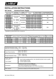
2 System Overview<br />
<strong>E1200</strong> <strong>Installation</strong> <strong>Guide</strong><br />
Typical servo system E12x0-XX: <strong>Servo</strong> drive, linear motor and power supply.<br />
NTI AG / <strong>LinMot</strong> ® www.<strong>LinMot</strong>.com Page 5/20
<strong>LinMot</strong> <strong>Installation</strong> <strong>Guide</strong><br />
3 Functionality and Interfaces<br />
Supply Voltage<br />
Motor Supply 72VDC (24...85VDC) ● ● ● ● ● ● ● ●<br />
Logic Supply 24VDC (22...26VDC) ● ● ● ● ● ● ● ●<br />
Motor Phase Current<br />
32A peak / 12A rms ● ● ● ● ● ● ● ●<br />
Controllable Motors<br />
<strong>LinMot</strong> P01-23x… (Motor Link P) * ● ● ● ● ● ● ● ●<br />
P01-37x… (Motor Link P) * ● ● ● ● ● ● ● ●<br />
P01-48x… (Motor Link P) * ● ● ● ● ● ● ● ●<br />
DC Motors ● ● ● ● ● ● ● ●<br />
Brushless DC / EC Motors ● ● ● ● ● ● ● ●<br />
Command Interface<br />
CANopen ● ● ● ● ● ● ● ●<br />
LinRS ● ● ● ● ● ● ● ●<br />
POWERLINK<br />
●<br />
PROFINET<br />
●<br />
sercos<br />
●<br />
Sercos over EtherCAT ● ●<br />
ETHERNET IP<br />
●<br />
EtherCAT ● ●<br />
PROFIBUS-DP<br />
●<br />
Programmable Motion Profiles (Curves)<br />
Up to 100 Motion Profiles ● ● ● ● ● ● ● ●<br />
Programmable Command Table<br />
Command Table with up to 255 entries ● ● ● ● ● ● ● ●<br />
External Position Sensor<br />
Incremental<br />
(RS422 up to 25 M counts/s, quadrature ev.)<br />
● ● ● ● ● ● ● ●<br />
Synchronisation<br />
Master Encoder In/Out<br />
(RS422 up to 25 M counts/s, quadrature ev.)<br />
● ● ● ● ● ● ● ●<br />
Configuration Interface<br />
RS232 ● ● ● ● ● ● ● ●<br />
Ethernet 10/100 Mbit/s<br />
(2-Port Switch integrated)<br />
● ● ● ● ● ● ● ●<br />
E1250-PL-UC<br />
E1250-PN-UC<br />
E1250-SC-UC<br />
E1250-IP-UC<br />
E1250-EC-UC<br />
E1250-SE-UC<br />
E1230-DP-UC<br />
<strong>E1200</strong>-GP-UC<br />
<strong>E1200</strong> <strong>Installation</strong> <strong>Guide</strong><br />
4 IP Address Selection<br />
The default mode for acquiring an IP address is via DHCP. If no servers respond on<br />
the connected network, the drive switches to the Ipv4 Link-Local addressing<br />
scheme (also known as APIPA on Windows systems). This way the drive<br />
automatically assigns itself an address within the range of 169.254.0.1 through<br />
169.254.255.254 (Subnet Mask 255.255.0.0).<br />
Please note that this process can take up to a minute until a valid address is<br />
assigned to the drive.<br />
* <strong>LinMot</strong> Motor Communication<br />
NTI AG / <strong>LinMot</strong> ® www.<strong>LinMot</strong>.com Page 6/20
<strong>LinMot</strong> <strong>Installation</strong> <strong>Guide</strong><br />
5 Power Supply and Grounding<br />
<strong>E1200</strong> <strong>Installation</strong> <strong>Guide</strong><br />
In order to assure a safe and error free operation, and to avoid severe<br />
damage to system components, all system components* must be well<br />
grounded to either a single earth or utility ground. This includes both<br />
<strong>LinMot</strong> and all other control system components on the same ground<br />
bus.<br />
Each system component* should be tied directly to the ground bus (star<br />
pattern), rather than daisy chaining from component to component.<br />
(<strong>LinMot</strong> motors are properly grounded through their power cables when<br />
connected to <strong>LinMot</strong> drives.)<br />
Power supply connectors must not be connected or disconnected<br />
while DC voltage is present. Do not disconnect system components<br />
until all <strong>LinMot</strong> drive LEDs have turned off. (Capacitors in the power<br />
supply may not fully discharge for several minutes after input voltage<br />
has been disconnected). Failure to observe these precautions may<br />
result in severe damage to electronic components in <strong>LinMot</strong> motors<br />
and/or drives.<br />
Do not switch Power Supply DC Voltage. All power supply switching<br />
and E-Stop breaks should be done to the AC supply voltage of the<br />
power supply. Failure to observe these precautions may result in severe<br />
damage to the drive.<br />
* Inside of the <strong>E1200</strong> drive the PWR motor GND and PWR signal GND is connected together and to<br />
the GND of the drive housing. It is recommended that the PWR motor GND is NOT grounded at<br />
another place than inside of the drive to reduce circular currents.<br />
NTI AG / <strong>LinMot</strong> ® www.<strong>LinMot</strong>.com Page 7/20
<strong>LinMot</strong> <strong>Installation</strong> <strong>Guide</strong><br />
6 Description of the connectors / Interfaces<br />
6.1 X1<br />
X1<br />
Motor Supply / Regeneration Resistor<br />
<strong>E1200</strong> <strong>Installation</strong> <strong>Guide</strong><br />
Screw Terminals External Regeneration Resistor (RR01-10/60, Art. Nr. 0150-3088)<br />
External Fuse: max. 32AT (for example RK5 Class Fuse Bussmann FRN-R-30)<br />
Supply nominal 72VDC (24...85VDC / 30..85VDC for UL compliance)<br />
(See chapter Power Supply Requirements for compatible power supplies.)<br />
Absolute max. Rating 72VDC +20%.<br />
If motor supply voltage is exceeds 90VDC, the drive will go into error state.<br />
- Tightening torque: 0.5 - 0.6 Nm<br />
- Screw thread: M2.5<br />
- Use 60/75°C copper conductors only<br />
- Conductor cross-section: use only 2.5mm 2 / AWG 14<br />
- Stripping length: 13-15mm<br />
- Max. length: 4m<br />
6.2 X2<br />
X2<br />
Motor Phases<br />
<strong>LinMot</strong> Motor:<br />
3-phase EC-Motor:<br />
PH1+ /U<br />
PH1- /V<br />
PH2+ /W<br />
PH2- /X<br />
SCRN<br />
Motor Phase 1+ red Motor Phase U<br />
Motor Phase 1- pink Motor Phase V<br />
Motor Phase 2+ blue Motor Phase W<br />
Motor Phase 2- grey Motor Phase X<br />
Shield<br />
Screw Terminals<br />
- Tightening torque: 0.5 - 0.6 Nm<br />
- Screw thread: M2.5<br />
- Use 60/75°C copper conductors only<br />
- Conductor cross-section: 0.5 – 2.5mm 2 (depends on Motor current) / AWG 21 -14<br />
- Stripping length 13-15mm<br />
NTI AG / <strong>LinMot</strong> ® www.<strong>LinMot</strong>.com Page 8/20
<strong>LinMot</strong> <strong>Installation</strong> <strong>Guide</strong><br />
6.3 X3<br />
X3<br />
Motor Encoder<br />
<strong>LinMot</strong> Motor:<br />
3-phase EC-Motor:<br />
DSUB-9 (f)<br />
1<br />
2<br />
3<br />
4<br />
5<br />
6<br />
7<br />
8<br />
9<br />
case<br />
- -<br />
- -<br />
+5VDC<br />
+5VDC (Hall Supply)<br />
Sensor Sine Hall 1<br />
Temp. In Hall 3<br />
- -<br />
- -<br />
AGND<br />
AGND (Hall Supply)<br />
Sensor Cosine Hall 2<br />
Shield<br />
Note:<br />
Use +5VDC (X3.3) and AGND (X3.8) only for motor internal hall sensor supply (max. 100mA).<br />
Caution:<br />
Do NOT connect AGND (X3.8) to ground or earth!<br />
<strong>E1200</strong> <strong>Installation</strong> <strong>Guide</strong><br />
Motor Wiring<br />
NTI AG / <strong>LinMot</strong> ® www.<strong>LinMot</strong>.com Page 9/20
<strong>LinMot</strong> <strong>Installation</strong> <strong>Guide</strong><br />
6.4 X4<br />
X4<br />
Logic Supply / Control<br />
12<br />
11<br />
10<br />
9<br />
8<br />
7<br />
6<br />
5<br />
4<br />
3<br />
2<br />
1<br />
Input SVE<br />
I/O X4.11<br />
I/O X4.10<br />
I/O X4.9<br />
I/O X4.8<br />
I/O X4.7<br />
I/O X4.6<br />
I/O X4.5<br />
I/O X4.4<br />
I/O X4.3/Brk<br />
+24VDC Supply<br />
GND Supply<br />
Power Stage Enable (HW Enable)<br />
Configurable IO, PTC2 Input<br />
Configurable IO, PTC1 Input<br />
Configurable IO<br />
Configurable IO<br />
Configurable IO, Analog Input for EasySteps Application<br />
Configurable IO, Trigger Input<br />
Configurable IO<br />
Configurable IO, Analog Input (configurable as high imp. Input)<br />
Configurable IO, Brake <strong>Drive</strong>r 1A<br />
Logic Supply 22-26 VDC<br />
Ground<br />
<strong>E1200</strong> <strong>Installation</strong> <strong>Guide</strong><br />
Phoenix<br />
MC1,5/12-STF-<br />
3,5<br />
Inputs (X4.3 .. X4.12):<br />
Outputs (X4.4 .. X4.11):<br />
Brake Output (X4.3):<br />
24V / 5mA (Low Level: –0.5 to 5VDC, High Level: 15 to 30VDC)<br />
24V / max.100mA, Peak 370mA (will shut down if exceeded)<br />
24V / max.1.0A<br />
Input X4.12: SVE (Safety Voltage Enable) must be high for enabling the power stage. ). If it goes low for<br />
more than 0.5ms the PWM generation of the power stage is disabled by hardware.<br />
Supply 24V / typ. 400mA / max. 2.1A (if all outputs “on” with max. load.)<br />
- Tightening torque: min 0.22Nm<br />
- Screw thread: M2<br />
- Use 60/75°C copper conductors only<br />
- Conductor cross-section max. 1.5mm 2<br />
- Internal Fuse (F2): 3AT (slow blow, Schurter OMT125, 3404.0118.xx, UL File Number: E41599)<br />
CAUTION: For continued protection against risk of fire, replace only with same type and rating of fuse.<br />
6.5 X7 - X8<br />
X7 - X8<br />
RS485/CAN<br />
1<br />
2<br />
3<br />
4<br />
5<br />
6<br />
7<br />
8<br />
case<br />
RS485_Rx+<br />
RS485_Rx-<br />
RS485_Tx+<br />
GND<br />
GND<br />
RS485_Tx-<br />
CAN_H<br />
CAN_L<br />
Shield<br />
A<br />
B<br />
Y<br />
Z<br />
RJ-45<br />
Use twisted pair (1-2, 3-6, 4-5, 7-8) cable for wiring.<br />
The built in CAN and RS485 terminations can be activated by S5.2 and S5.3.<br />
X7 is internally connected to X8 (1:1 connection)<br />
NTI AG / <strong>LinMot</strong> ® www.<strong>LinMot</strong>.com Page 10/20
<strong>LinMot</strong> <strong>Installation</strong> <strong>Guide</strong><br />
6.6 X9<br />
X9<br />
PROFIBUS DP (only available on E1230-DP-UC)<br />
DSUB-9 (f)<br />
6.7 X10 - X11<br />
1<br />
2<br />
3<br />
4<br />
5<br />
6<br />
7<br />
8<br />
9<br />
case<br />
Max. Baud rate: 12Mbaud<br />
Not connected<br />
Not connected<br />
RxD/TxD-P<br />
CNTR-P<br />
GND<br />
(isolated)<br />
+5V (isolated)<br />
Not connected<br />
RxD/TxD-N<br />
Not connected<br />
Shield<br />
<strong>E1200</strong> <strong>Installation</strong> <strong>Guide</strong><br />
X10 - X11<br />
Master Encoder IN (X10) / Master Encoder OUT (X11)<br />
Incremental:<br />
Step/Direction:<br />
EIA/TIA 568A colors:<br />
1<br />
2<br />
3<br />
4<br />
5<br />
6<br />
7<br />
8<br />
case<br />
A+ Step+<br />
A- Step-<br />
B+ Direction+<br />
Z+ Zero+<br />
Z- Zero-<br />
B- Direction-<br />
CAN_H<br />
CAN_H<br />
CAN_L<br />
CAN_L<br />
Shield<br />
Shield<br />
Green/White<br />
Green<br />
Orange/White<br />
Blue<br />
Blue/White<br />
Orange<br />
Brown/White<br />
Brown<br />
RJ-45<br />
Use twisted pair (1-2, 3-6, 4-5, 7-8) cable for wiring.<br />
Master Encoder Inputs:<br />
40ns edge separation<br />
Master Encoder Outputs:<br />
Diff. RS422, max. counting frequency 25 Mcounts/s, quadrature evaluation,<br />
Amplified RS422 differential signals from Master Encoder IN (X10)<br />
The CAN bus can be terminated with S5.4.<br />
All devices, which are connected to X10/X11 must be referenced to the same ground.<br />
NTI AG / <strong>LinMot</strong> ® www.<strong>LinMot</strong>.com Page 11/20
<strong>LinMot</strong> <strong>Installation</strong> <strong>Guide</strong><br />
6.8 X13<br />
X13 External Position Sensor Differential Hall Switches / SSI<br />
ABZ with Hall Switches<br />
Sin/Cos 1Vpp with SSI<br />
1<br />
2<br />
3<br />
4<br />
5<br />
6<br />
7<br />
8<br />
case<br />
9<br />
10<br />
11<br />
12<br />
13<br />
14<br />
15<br />
+5V DC<br />
A-<br />
B-<br />
Z-<br />
GND<br />
U-<br />
V-<br />
W-<br />
Shield<br />
A+<br />
B+<br />
Z+<br />
Encoder Alarm<br />
U+<br />
V+<br />
W+<br />
+5V DC<br />
GND<br />
Sin-<br />
Cos-<br />
Data-<br />
Clock-<br />
Shield<br />
Sin+<br />
Cos+<br />
Data+<br />
Encoder Alarm<br />
Clock+<br />
<strong>E1200</strong> <strong>Installation</strong> <strong>Guide</strong><br />
DSUB-15 (f)<br />
Position Encoder Inputs (RS422):<br />
Max. counting frequency: 25 Mcounts/s with quadrature decoding, 40ns edge separation<br />
Encoder Simulation Outputs (RS422):<br />
Max Output Frequency: 2.5MHz, 5 M counts/s with quadrature decoding, 200ns edge separation<br />
Differential Hall Switch Inputs (RS422):<br />
Input Frequency:
<strong>LinMot</strong> <strong>Installation</strong> <strong>Guide</strong><br />
6.10 X17 - X18<br />
X17 - X18<br />
RealTime Ethernet 10/100 Mbit/s<br />
X17 RT ETH In<br />
X18 RT ETH Out<br />
RJ-45<br />
6.11 X19<br />
Specification depends on RT-Bus Type. Please refer to according documentation.<br />
<strong>E1200</strong> <strong>Installation</strong> <strong>Guide</strong><br />
X19<br />
System<br />
1<br />
2<br />
3<br />
4<br />
5<br />
6<br />
7<br />
8<br />
case<br />
(Do not connect)<br />
(Do not connect)<br />
RS232 Rx<br />
GND<br />
GND<br />
RS232 Tx<br />
(Do not connect)<br />
(Do not connect)<br />
Shield<br />
RJ-45<br />
Use Adapter cable AC01-RJ45/Df-2.5-RS1 (Art.-No. 0150-2143) for Configuration over RS232.<br />
6.12 X20<br />
X20<br />
Analog In (+-10V Differential Analog Input)<br />
1<br />
2<br />
3<br />
4<br />
5<br />
6<br />
7<br />
8<br />
case<br />
(Do not connect)<br />
(Do not connect)<br />
Analog In -<br />
GND<br />
GND<br />
Analog In +<br />
(Do not connect)<br />
(Do not connect)<br />
Shield<br />
RJ-45<br />
NTI AG / <strong>LinMot</strong> ® www.<strong>LinMot</strong>.com Page 13/20
<strong>LinMot</strong> <strong>Installation</strong> <strong>Guide</strong><br />
6.13 S5<br />
S5<br />
Bus Termination / AnaIn2 Pull Down<br />
S5<br />
Switch 1: AnIn2 Pull down (4k7 Pull down on X4.4). Set to ON, if X4.4 is used as digital Output.<br />
6.14 LEDs<br />
LEDs<br />
State Display<br />
Switch 2: Termination Resistor for RS485 on CMD (120R between pin 1 and 2 on X7/X8) on/off<br />
Switch 3: CAN Termination on CMD (120R between pin 7 and 8 on X7/X8) on/off<br />
Switch 4: CAN Termination on ME (120R between pin 7 and 8 on X10/X11) on/off<br />
Factory setting: all switches “off”<br />
<strong>E1200</strong> <strong>Installation</strong> <strong>Guide</strong><br />
Green<br />
Yellow<br />
Yellow<br />
Red<br />
24V Logic Supply OK<br />
Motor Enabled / Error Code Low Nibble<br />
Warning / Error Code High Nibble<br />
Error<br />
6.15 RT BUS LEDs<br />
RT Bus LEDs<br />
RT Bus State Display<br />
Green<br />
Red<br />
OK<br />
Error<br />
The use of these LEDs depends on the type of fieldbus which is used. Please see the corresponding<br />
manual for further information.<br />
6.16 S1 - S2<br />
S1 - S2<br />
E12x0 V1<br />
Address Selectors<br />
E12x0 V2<br />
S1 (5..8)<br />
Bus ID High (0 … F). Bit 5 is LSB, bit 8 MSB.<br />
S2 (1..4)<br />
Bus ID Low (0 … F). Bit 1 is LSB, bit 4 MSB.<br />
The use of these switches depends on the type of fieldbus which is used. Please see the corresponding manual for further<br />
information.<br />
NTI AG / <strong>LinMot</strong> ® www.<strong>LinMot</strong>.com Page 14/20
<strong>LinMot</strong> <strong>Installation</strong> <strong>Guide</strong><br />
7 Error Codes<br />
Error Codes<br />
Error Warn EN Description<br />
Off Warning Operation<br />
Enabled<br />
On<br />
● ~2Hz<br />
0..15 x<br />
Error Code<br />
High Nibble<br />
● ~2Hz<br />
0..15 x<br />
Error Code<br />
Low Nibble<br />
Normal Operation:<br />
Warnings and operation enabled are displayed.<br />
Error:<br />
The error code is shown by a blink code with “WARN” and “EN”.<br />
The error byte is divided into low and high nibble (= 4 bit).<br />
”WARN” and “EN” are blinking together.<br />
The error can be acknowledged.<br />
(e.g.: WARN blinks 3x, EN blinks 2x; Error Code = 32h)<br />
<strong>E1200</strong> <strong>Installation</strong> <strong>Guide</strong><br />
● ~2Hz<br />
● ~2Hz<br />
0..15 x<br />
Error Code<br />
High Nibble<br />
● ~2Hz<br />
0..15 x<br />
Error Code<br />
Low Nibble<br />
Fatal Error:<br />
The error code is shown by a blink code with “WARN” and “EN”.<br />
The error byte is divided into low and high nibble.<br />
”WARN” and “EN” are blinking together.<br />
Fatal errors can only be acknowledged by a reset or power cycle.<br />
(e.g.: WARN blinks 3x, EN blinks 2x; Error Code = 32h)<br />
● ~4Hz<br />
● ~2Hz<br />
0..15 x<br />
Error Code<br />
High Nibble<br />
● ~2Hz<br />
0..15 x<br />
Error Code<br />
Low Nibble<br />
System Error:<br />
Please reinstall firmware or contact support.<br />
● ~0.5Hz ● ~0.5Hz On Signal Supply 24V too low:<br />
The error and warn LEDs blink alternating if the signal supply +24V (X4.2) is<br />
less than 18VDC.<br />
Off M●●● ●M●● Plug&Play Communication Active<br />
This sequence (Warn on, then En on, then both off, complete sequence of the<br />
4 states ca. 1Sec) signalizes the state when the plug and play parameters are<br />
being read from the motor.<br />
The meaning of the error codes can be found in the<br />
Usermanual_MotionCtrlSW_SG5 and the user manual of the installed interface<br />
software. These documents are provided together with <strong>LinMot</strong>-Talk configuration<br />
software and can be downloaded from www.linmot.com.<br />
NTI AG / <strong>LinMot</strong> ® www.<strong>LinMot</strong>.com Page 15/20
<strong>LinMot</strong> <strong>Installation</strong> <strong>Guide</strong><br />
8 Physical Dimensions<br />
<strong>E1200</strong> Series single axis drive<br />
Width mm (in) 40 (1.6)<br />
Height mm (in) 233 (9.2)<br />
Height with fixings mm (in) 270 (10.7)<br />
Depth mm (in) 180 (7.1)<br />
Weight kg (lb) 1.5 (3.3)<br />
Case IP 20<br />
Storage Temperature °C -25…40<br />
Transport Temperature °C -25…70<br />
Operating Temperature °C 0…40 at rated data<br />
40...50 with power derating<br />
Relative humidity<br />
95% (non-condensing)<br />
<strong>E1200</strong> <strong>Installation</strong> <strong>Guide</strong><br />
Max. Case Temperature °C 65<br />
Max. Power Dissipation W 30<br />
Clearance around drives mm (in) 20 (0.8) left/right<br />
50 (2) top / bottom<br />
NTI AG / <strong>LinMot</strong> ® www.<strong>LinMot</strong>.com Page 16/20
<strong>LinMot</strong> <strong>Installation</strong> <strong>Guide</strong><br />
9 Power Supply Requirements<br />
Motor Power Supply<br />
The calculation of the needed power for the Motor supply is depending on the<br />
application and the used motor. The nominal supply voltage is 72- 80 VDC. The<br />
possible range is from 24 to 85VDC, for UL from 30 to 85 VDC.<br />
ATTENTION: The motor supply can rise up to 95 VDC when braking.<br />
This means that everything connected to that power supply needs a<br />
voltage rating of 100 VDC. (Additional capacitors, etc…). Due to high<br />
braking voltage and sudden load variations of linear motor<br />
applications, only specially designed power supplies can be used.<br />
<strong>E1200</strong> <strong>Installation</strong> <strong>Guide</strong><br />
Compatible Power supplies:<br />
Item Description Art. No.<br />
T01-72/420 72VDC, 15A peak, 420VA, 3x400VAC 0150-1966<br />
T01-72/420-US 72VDC, 15A peak, 420VA, 3x230VAC 0150-1967<br />
T01-72/900 72VDC, 30A peak, 900VA, 3x400VAC 0150-1842<br />
T01-72/900-US 72VDC, 30A peak, 900VA, 3x230VAC 0150-1843<br />
T01-72/1500 72VDC, 2x30A peak, 1500VA, 3x400VAC 0150-1844<br />
T01-72/1500-US 72VDC, 2x30A peak, 1500VA, 3x230VAC 0150-1845<br />
S01-72/500 72VDC, 500W, 750W peak, 1x100..120VAC/200..240VAC 0150-1874<br />
S01-72/1000 72VDC, 1000W, 2000W peak, 3x380..500VAC 0150-1872<br />
For compatibility with other power supplies, contact support@linmot.com<br />
Signal Power Supply<br />
The logic supply needs a regulated power supply of a nominal voltage of 24 VDC.<br />
The voltage must be between 22 and 26 VDC.<br />
Current consumption:<br />
min. 200mA (no load on the outputs)<br />
typ. 1.1A<br />
max. 2.1A<br />
(all 10 outputs “on” with 100mA load and /Break with no load)<br />
(all 10 outputs “on” with 100mA load and /Break with 1A load)<br />
NTI AG / <strong>LinMot</strong> ® www.<strong>LinMot</strong>.com Page 17/20
<strong>LinMot</strong> <strong>Installation</strong> <strong>Guide</strong><br />
10 Regeneration of Power / Regeneration Resistor<br />
There are two possibilities to deal with power regeneration:<br />
Option A:<br />
Option B:<br />
Connect an additional capacitor to the motor power supply. It is<br />
recommended to use a capacitor >= 10’000 µF<br />
(install capacitor close to the power supply!)<br />
Install a regeneration resistor to X1 (RR+ and RR-). The threshold<br />
value of the voltage depends on the used motor voltage power supply.<br />
The max. threshold value must not exceed 88 VDC.<br />
For UL applications, use option A.<br />
Item Description Art. No.<br />
Capacitor Capacitor 10’000 µF / 100 V 0150-3075<br />
<strong>E1200</strong> <strong>Installation</strong> <strong>Guide</strong><br />
Regeneration Resistor R01-10/60 (10 Ohm, 60 W) 0150-3088<br />
Regeneration Resistor RR01-10/150 (10 Ohm, 150 W) 0150-3090<br />
11 Ordering Information<br />
Item Description Art. No.<br />
E1250-PL-UC POWERLINK <strong>Servo</strong> <strong>Drive</strong> 72VDC/32A 0150-1760<br />
E1250-PN-UC PROFINET <strong>Servo</strong> <strong>Drive</strong> 72VDC/32A 0150-1762<br />
E1250-EC-UC EtherCAT <strong>Servo</strong> <strong>Drive</strong> 72VDC/32A 0150-1763<br />
E1250-SE-UC sercos over EtherCAT <strong>Servo</strong> <strong>Drive</strong> 72VDC/32A 0150-1898<br />
E1250-SC-UC sercos <strong>Servo</strong> <strong>Drive</strong> 72VDC/32A 0150-1764<br />
E1250-IP-UC ETHERNET IP <strong>Servo</strong> <strong>Drive</strong> 72VDC/32A 0150-1761<br />
E1230-DP-UC PROFIBUS-DP <strong>Servo</strong> <strong>Drive</strong> 72VDC/32A 0150-1766<br />
<strong>E1200</strong>-GP-UC GENERAL PURPOSE <strong>Servo</strong> <strong>Drive</strong> 72VDC/32A 0150-1771<br />
RS232<br />
configuration cable<br />
AC01-RJ45/Df-2.5-RS1 0150-2143<br />
12 International Certifications<br />
Certifications<br />
Europe<br />
See chapter “14 Declaration of Conformity CE-Marking“<br />
NTI AG / <strong>LinMot</strong> ® www.<strong>LinMot</strong>.com Page 18/20
<strong>LinMot</strong> <strong>Installation</strong> <strong>Guide</strong><br />
13 Classification of the safety functionality<br />
<strong>Drive</strong>s classification accordance with the new machinery directive EN ISO 13849-1:<br />
The safety function SVE (“Safety Voltage Enable”) on the <strong>LinMot</strong> drive series <strong>E1200</strong>, which is to<br />
provide the safe stop, fulfills the following criteria of the new machinery directive EN ISO 13849-1:<br />
Category cat = 3<br />
Performance Level PL = d<br />
Diagnostic Coverage CD = medium<br />
Mean time to hazardous failure of one channel MTTFd = 49.8 Years<br />
14 Declaration of Conformity CE-Marking<br />
Manufacturer: NTI AG <strong>LinMot</strong> ®<br />
Haerdlistrasse 15<br />
8957 Spreitenbach<br />
Switzerland<br />
Tel.: +41 (0)56 419 91 91<br />
Fax: +41 (0)56 419 91 92<br />
<strong>E1200</strong> <strong>Installation</strong> <strong>Guide</strong><br />
Products:<br />
<strong>LinMot</strong> ® <strong>Drive</strong>s<br />
Type Art.-No. Type Art-No. Type Art.-No.<br />
E1250-PL-UC 0150-1760 E1250-EC-UC 0150-1763 <strong>E1200</strong>-GP-UC 0150-1771<br />
E1250-IP-UC 0150-1761 E1250-SC-UC 0150-1764 E1250-SE-UC 0150-1898<br />
E1250-PN-UC 0150-1762 E1230-DP-UC 0150-1766<br />
The product must be mounted and used in strict accordance with the installation instruction<br />
contained within the installation guide, a copy of which may be obtained from NTI Ltd.<br />
I declare that as the authorized representative, the above information in relation to the<br />
supply/manufacture of this product is in conformity with the stated standards and other related<br />
documents in compliance with the protection requirements of the Electromagnetic Compatibility<br />
(EMC) Directive 2004/108/EC.<br />
Standards Complied with:<br />
EN 61000-6-2<br />
Compliance<br />
Criteria<br />
Immunity for industrial environment<br />
EN 61000-4-2 B Electrostatic discharge immunity (ESD)<br />
EN 61000-4-3 A Radiated electromagnetic field immunity<br />
EN 61000-4-4 B Fast transients / burst immunity (EFT)<br />
EN 61000-4-5 B Slow transients immunity (Surges)<br />
EN 61000-4-6 A Conducted radio frequency immunity<br />
EN 61000-4-8 A Power frequency magnetic field immunity<br />
EN 61000-6-4 Class Emission for industrial environment<br />
EN 55022 B Radiated Emission<br />
Company: NTI Ltd. / Spreitenbach / October 13, 2010<br />
--------------------------------------------<br />
R. Rohner / CEO NTI AG<br />
NTI AG / <strong>LinMot</strong> ® www.<strong>LinMot</strong>.com Page 19/20
<strong>LinMot</strong> <strong>Installation</strong> <strong>Guide</strong><br />
15 Contact Addresses<br />
SWITZERLAND<br />
NTI AG<br />
Haerdlistr. 15<br />
CH-8957 Spreitenbach<br />
Sales and Administration: +41-(0)56-419 91 91<br />
office@linmot.com<br />
Tech. Support: +41-(0)56-544 71 00<br />
support@linmot.com<br />
Tech. Support (Skype) :<br />
skype:support.linmot<br />
Fax: +41-(0)56-419 91 92<br />
Web:<br />
http://www.linmot.com/<br />
<strong>E1200</strong> <strong>Installation</strong> <strong>Guide</strong><br />
USA<br />
<strong>LinMot</strong>, Inc.<br />
204 E Morrissey Dr.<br />
Elkhorn, WI 53121<br />
Sales and Administration: 877-546-3270<br />
262-743-2555<br />
Tech. Support: 877-804-0718<br />
262-743-1284<br />
Fax: 800-463-8708<br />
262-723-6688<br />
E-Mail:<br />
Web:<br />
us-sales@linmot.com<br />
http://www.linmot-usa.com/<br />
Please visit http://www.linmot.com/ to find the distributor closest to you.<br />
Smart solutions are…<br />
NTI AG / <strong>LinMot</strong> ® www.<strong>LinMot</strong>.com Page 20/20