LinUDP Interface - LinMot
LinUDP Interface - LinMot
LinUDP Interface - LinMot

You also want an ePaper? Increase the reach of your titles
YUMPU automatically turns print PDFs into web optimized ePapers that Google loves.
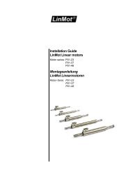
Documentation of the <strong>LinUDP</strong> <strong>Interface</strong> of the following Drives:<br />
- E1250-IP-UC<br />
- E1400-IP-QN<br />
<strong>LinUDP</strong> <strong>Interface</strong><br />
User Manual
<strong>LinMot</strong> User Manual<br />
<strong>LinMot</strong> User Manual<br />
© 2013 NTI AG<br />
This work is protected by copyright.<br />
Under the copyright laws, this publication may not be reproduced or transmitted in any form, electronic or mechanical, including<br />
photocopying, recording, microfilm, storing in an information retrieval system, not even for didactical use, or translating, in whole or in<br />
part, without the prior written consent of NTI AG.<br />
<strong>LinMot</strong>® is a registered trademark of NTI AG.<br />
The information in this documentation reflects the stage of development at the time of press and is therefore without obligation.<br />
NTI AG reserves itself the right to make changes at any time and without notice to reflect further technical advance or product<br />
improvement.<br />
Document version 1.3a / ka, December 2013<br />
NTI AG / <strong>LinMot</strong> ® www.<strong>LinMot</strong>.com Page 2/19
<strong>LinMot</strong> User Manual<br />
Table of Content<br />
1 Overview...........................................................................................................................4<br />
2 Installation on Servo Drive..............................................................................................4<br />
3 Connecting <strong>LinUDP</strong>.........................................................................................................4<br />
3.1 Pin Assignment of the Connectors X17 - X18............................................................4<br />
4 <strong>LinUDP</strong> Telegram.............................................................................................................5<br />
4.1 DHCP Header.............................................................................................................5<br />
4.2 IPv4 Header................................................................................................................5<br />
4.3 <strong>LinUDP</strong> Header...........................................................................................................5<br />
4.4 <strong>LinUDP</strong> Data...............................................................................................................5<br />
4.4.1 Request from the Master.....................................................................................6<br />
4.4.2 Response from the Drive.....................................................................................7<br />
5 <strong>LinUDP</strong> Parameters..........................................................................................................7<br />
6 <strong>LinUDP</strong> Modules...............................................................................................................8<br />
6.1 Master to drive Modules.............................................................................................8<br />
6.2 Drive to master Modules.............................................................................................9<br />
7 Real Time Config Module..............................................................................................10<br />
8 Contact Addresses........................................................................................................19<br />
<strong>LinMot</strong> User Manual<br />
NTI AG / <strong>LinMot</strong> ® www.<strong>LinMot</strong>.com Page 3/19
<strong>LinMot</strong> User Manual<br />
1 Overview<br />
The <strong>LinUDP</strong> protocol is an easy way for communication with a <strong>LinMot</strong> servo drive<br />
over Ethernet. There are no checks done to make sure if the messages have<br />
reached their destination and if they are correctly received. When communicating<br />
via <strong>LinUDP</strong>, the drive has no active function, it only responds to requests with the<br />
appropriate answers.<br />
2 Installation on Servo Drive<br />
For installing the <strong>LinUDP</strong> firmware on the servo drive, start the <strong>LinMot</strong>- Talk<br />
software and press the install firmware button . Choose the file<br />
“Firmware_Buildxxxxxxxx.sct” and press “Open”. The wizard will guide you through<br />
the installation. When asking for the interface software choose “<strong>LinUDP</strong>”:<br />
<strong>LinMot</strong> User Manual<br />
Press ok and follow the rest of the wizard.<br />
3 Connecting <strong>LinUDP</strong><br />
3.1 Pin Assignment of the Connectors X17 - X18<br />
The Ethernet/IP connector is a standard RJ45 female connector with a pin<br />
assignment as defined by EIA/TIA T568B:<br />
X17 – X18<br />
RealTime Ethernet Connector<br />
Pin Wire color code Assignment 100BASE-TX<br />
1<br />
2<br />
3<br />
4<br />
5<br />
6<br />
7<br />
8<br />
case<br />
WHT/ORG<br />
ORG<br />
WHT/GRN<br />
BLU<br />
WHT/BLU<br />
GRN<br />
WHT/BRN<br />
BRN<br />
-<br />
Rx+<br />
Rx-<br />
Tx+<br />
-<br />
-<br />
Tx-<br />
-<br />
-<br />
-<br />
RJ-45<br />
Use standard patch cables (twisted pair, S/UTP, AWG26) for<br />
wiring. This type of cable is usually referred to as a “Cat5e-<br />
Cable”.<br />
NTI AG / <strong>LinMot</strong> ® www.<strong>LinMot</strong>.com Page 4/19
<strong>LinMot</strong> User Manual<br />
4 <strong>LinUDP</strong> Telegram<br />
In <strong>LinUDP</strong> there are two telegrams used, one for the request from the master and<br />
the other one for the response from the drive. These two telegrams have the<br />
following layout:<br />
Name<br />
Size [Byte]<br />
DHCP Header 14<br />
IPv4 Header 20<br />
<strong>LinUDP</strong> Header 8<br />
<strong>LinUDP</strong> Data<br />
message dependent<br />
<strong>LinMot</strong> User Manual<br />
4.1 DHCP Header<br />
The DHCP Header looks like in the following table.<br />
0. Byte 1. Byte 2. Byte 3. Byte 4. Byte 5. Byte 6. Byte 7. Byte<br />
+0 Destination MAC ID<br />
+8 Source MAC ID Protocol Typ (0x0800)<br />
4.2 IPv4 Header<br />
The IPv4 header is described in the rfc0791 in chapter 3.1. Rfc0791 could be found<br />
on www.ietf.org/rfc/rfc0791.txt. The sections options and padding are not used.<br />
4.3 <strong>LinUDP</strong> Header<br />
The <strong>LinUDP</strong> header consists of four parts. They are showing ind the following table.<br />
Name<br />
Size [Byte]<br />
Source Port 2<br />
Destination Port 2<br />
Length of UDP Telegram 2<br />
UDP Checksum 2<br />
The <strong>LinUDP</strong> ports are fix assigned. For the Master it is port 41136 and for the drive<br />
it is port 49360. In Hex-Code they are A0B0 and C0D0.<br />
4.4 <strong>LinUDP</strong> Data<br />
In <strong>LinUDP</strong> data are the data which we want to transfer. The construction of this data<br />
NTI AG / <strong>LinMot</strong> ® www.<strong>LinMot</strong>.com Page 5/19
<strong>LinMot</strong> User Manual<br />
part always is the same. The only difference are the source and destination, they<br />
are switched.<br />
4.4.1 Request from the Master<br />
The first 32 bits of the <strong>LinUDP</strong> data define the request and the following 32 bits<br />
define the format of the response. The following tables show how the request<br />
definition and the response definition look like.<br />
Request definition<br />
Bit Name Data size [Byte]<br />
0 Control Word 2<br />
1 MC <strong>Interface</strong> 32<br />
2 Realtime Configuration 8<br />
<strong>LinMot</strong> User Manual<br />
3 – 31 Reserved for future expansions<br />
Response definition<br />
Bit Name Data size [Byte]<br />
0 Status Word 2<br />
1 State Var 2<br />
2 Actual Position 4<br />
3 Demand Position 4<br />
4 Current 2<br />
5 Warn Word 2<br />
6 Error Code 2<br />
7 Monitoring Channel 16<br />
8 Realtime Configuration 8<br />
9 – 31 Reserved for future expansions<br />
Each of the definition bits shows if the corresponding parameter is part of the<br />
communication. The order of the requested data parts is the same as the definition<br />
bits. When a definition bit is not set, the data part would not be transferred. When<br />
all bits of the request definition are set, then the <strong>LinUDP</strong> data looks like it is shown<br />
in the following table. Each field represents one byte.<br />
NTI AG / <strong>LinMot</strong> ® www.<strong>LinMot</strong>.com Page 6/19
<strong>LinMot</strong> User Manual<br />
0. Byte 1. Byte 2. Byte 3. Byte 4. Byte 5. Byte 6. Byte 7. Byte<br />
+0 Request Definition Response Definition<br />
+8 Control Word<br />
+16<br />
+24 MC <strong>Interface</strong><br />
+32<br />
+40 Realtime Configuration<br />
+48<br />
<strong>LinMot</strong> User Manual<br />
4.4.2 Response from the Drive<br />
The <strong>LinUDP</strong> data part of a response from a drive has the same construction like the<br />
data part of a request. The order of the response data part is the same as the<br />
response definition bits. The only exception is the last part of the response data part<br />
with the realtime configuration data, when realtime configuration is activated then<br />
the bit number 2 is set in de request definition and the bit number 8 is set in the<br />
response definition. When all bits in the response definition are set then the<br />
response data part looks like in the following table. If the response frame is shorter<br />
then 64 bytes, the drive fill the response with 0s until the length is 64 bytes.<br />
0. Byte 1. Byte 2. Byte 3. Byte 4. Byte 5. Byte 6. Byte 7. Byte<br />
+0 Request Definition Response Definition<br />
+8 Status Word State Var Actual Position<br />
+16 Demand Position Current Warn Word<br />
+24 Error Code Monitoring Channel<br />
+32<br />
+40 Realtime Configuration<br />
+48<br />
5 <strong>LinUDP</strong> Parameters<br />
The <strong>LinUDP</strong> servo drives have an additional parameter tree branch, which can be<br />
configured with the distributed <strong>LinMot</strong>-Talk software. With these parameters, the<br />
<strong>LinUDP</strong> behaviour can be defined. The <strong>LinMot</strong>-Talk software can be downloaded<br />
from http://www.linmot.com under the section download, software & manuals.<br />
The additional parameter tree branch is called “<strong>LinUDP</strong> Intf”. In this branch are the<br />
NTI AG / <strong>LinMot</strong> ® www.<strong>LinMot</strong>.com Page 7/19
<strong>LinMot</strong> User Manual<br />
following Parameters.<br />
• Dis-/Enable, with this Parameter the interface could be turned off and on.<br />
• Ethernet Configuration is the part where the connection type could be<br />
chosen.<br />
• Monitoring Channels defined 4 UPID. The values of this UPID are in the<br />
response data part when the monitoring channel bit is set active.<br />
Monitoring Channels<br />
Channel 1 UPID Source UPID for Monitoring Channel 1 Parameter UPID = 20A8<br />
Channel 2 UPID Source UPID for Monitoring Channel 2 Parameter UPID = 20A9<br />
Channel 3 UPID Source UPID for Monitoring Channel 3 Parameter UPID = 20AA<br />
Channel 4 UPID Source UPID for Monitoring Channel 4 Parameter UPID = 20AB<br />
<strong>LinMot</strong> User Manual<br />
• Master Configuration is for the communication safety. With the radio<br />
buttons under single master there can chosen three possibilities.<br />
• No Filter means the drive does no control. This option is choose per<br />
default.<br />
• Single Master means the drive takes the IP Address from the sender<br />
of the first <strong>LinUDP</strong> telegram, which it receives and after that it only<br />
responses to telegrams with this address.<br />
• Single Master with fix IP: In the parameters called Master IP Address<br />
define a IP Address and the drive only responses to telegrams with<br />
this fix address.<br />
• Master IP Address the fix IP address is defined in this parameters.<br />
6 <strong>LinUDP</strong> Modules<br />
In <strong>LinUDP</strong> there are three modules implemented for the master to drive<br />
communication and eight modules for the drive to master communication.<br />
6.1 Master to drive Modules<br />
Control Word<br />
With the control word the main state machine of the drive can be accessed. Please<br />
refer to “User Manual Motion Control Software” for the control word.<br />
MC Cmd <strong>Interface</strong><br />
This maps the MC command interface of the drive. Please refer to the<br />
documentation of the MC software.<br />
Real Time Configuration<br />
The real time configuration module allows accessing to parameters, variables,<br />
NTI AG / <strong>LinMot</strong> ® www.<strong>LinMot</strong>.com Page 8/19
<strong>LinMot</strong> User Manual<br />
curves, error log and command table. Also restart, start and stop of the drive can be<br />
initiated. Of course the parameter channel module works independently from the<br />
MC command interface. For this reason, changing a parameter and sending a<br />
motion command can be done in parallel. The real time configuration has influence<br />
on both telegram directions. For details see chapter 6 Real Time Config.<br />
6.2 Drive to master Modules<br />
Status Word<br />
The status word consists of 16 bits. Please refer to “User Manual Motion Control<br />
Software” for watch about the meaning of each bit the status word.<br />
State Var<br />
The State Var consists of MainState and SubState. Please refer to the table “State<br />
Var” on chapter 3 of the “User Manual Motion Control Software”. The State Var has<br />
all relevant flags and information for clean handshaking within one word and can<br />
therefore replace the modules “Get MC Header Echo” and “Get Error Code”.<br />
Actual Position<br />
Returns the actual position of the motor. (32 Bit integer value, resolution 0.1 μm)<br />
Demand Position<br />
Returns the demand position of the motor. (32 Bit integer value, resolution 0.1 μm)<br />
Current<br />
Returns the set current of the motor. (16 Bit integer value, resolution 1 mA)<br />
Warn Word<br />
Returns the warn word. Please refer to “User Manual Motion Control Software”.<br />
Error Code<br />
Returns the error code. Please refer to “User Manual Motion Control Software” for<br />
the Error Codes of the MC software.<br />
Monitoring Channel<br />
Transmits cyclically the value of the variable, which is defined by the monitoring<br />
channel Parameter (see chapter 3)<br />
<strong>LinMot</strong> User Manual<br />
NTI AG / <strong>LinMot</strong> ® www.<strong>LinMot</strong>.com Page 9/19
<strong>LinMot</strong> User Manual<br />
7 Real Time Config Module<br />
The structure of the real time config is shown in the following table. DO stands for<br />
data output and DI for data input. The point of view for the definition of DO and DI is<br />
the Master.<br />
Word number DO DI<br />
1. Parameter Channel Control Parameter Channel Status<br />
2. Argument (meaning depends on Cmd<br />
ID)<br />
3. Argument (meaning depends on Cmd<br />
ID)<br />
4. Argument (meaning depends on Cmd<br />
ID)<br />
Argument (meaning depends on Cmd<br />
ID)<br />
Argument (meaning depends on Cmd<br />
ID)<br />
Argument (meaning depends on Cmd<br />
ID)<br />
<strong>LinMot</strong> User Manual<br />
Real Time Config Control<br />
Parameter Command ID to be executed Reserved Command Count<br />
15 14 13 12 11 10 9 8 7 6 5 4 3 2 1 0<br />
The Parameter Channel Control is split in two parts:<br />
• Parameter Command ID to be executed (bits 8-15), see table Command ID<br />
• Command Count (bits 0-3)<br />
Real Time Config Status<br />
Parameter Status Reserved Command Count<br />
Response<br />
15 14 13 12 11 10 9 8 7 6 5 4 3 2 1 0<br />
The Parameter Channel Status is split in two parts:<br />
• Parameter Status (bits 8-15), see table Parameter Status<br />
• Command Count Response (bits 0-3)<br />
Command Count<br />
A new command is only evaluated, if the value of the command count changes. In<br />
the easiest way bit 0 could be toggled.<br />
NTI AG / <strong>LinMot</strong> ® www.<strong>LinMot</strong>.com Page 10/19
<strong>LinMot</strong> User Manual<br />
Parameter Command ID<br />
This selects the command.<br />
Possible Commands are:<br />
Command ID<br />
00h<br />
Parameter Access<br />
10h<br />
11h<br />
12h<br />
13h<br />
14h<br />
15h<br />
16h<br />
17h<br />
Parameter (UPID) List<br />
20h<br />
21h<br />
22h<br />
23h<br />
Stop / Start / Default<br />
30h<br />
31h<br />
32h<br />
33h<br />
34h<br />
35h<br />
36h<br />
Description<br />
No Operation<br />
Read ROM Value of Parameter by UPID<br />
Read RAM Value of Parameter by UPID<br />
Write ROM Value of Parameter by UPID<br />
Write RAM Value of Parameter by UPID<br />
Write RAM and ROM Value of Parameter by UPID<br />
Get minimal Value of Parameter by UPID<br />
Get maximal Value of Parameter by UPID<br />
Get default Value of Parameter by UPID<br />
Start Getting UPID List<br />
Get next UPID List item<br />
Start Getting Modified UPID List<br />
Get next Modified UPID List item<br />
Restart Drive<br />
Set parameter ROM values to default (OS SW)<br />
Set parameter ROM values to default (MC SW)<br />
Set parameter ROM values to default (<strong>Interface</strong> SW)<br />
Set parameter ROM values to default (Application SW)<br />
Stop MC and Application Software (for Flash access)<br />
Start MC and Application Software<br />
<strong>LinMot</strong> User Manual<br />
NTI AG / <strong>LinMot</strong> ® www.<strong>LinMot</strong>.com Page 11/19
<strong>LinMot</strong> User Manual<br />
Curve Service<br />
40h<br />
41h<br />
50h<br />
51h<br />
52h<br />
53h<br />
54h<br />
55h<br />
60h<br />
61h<br />
62h<br />
Error Log<br />
70h<br />
71h<br />
72h<br />
73h<br />
74h<br />
Command Table<br />
80h<br />
81h<br />
82h<br />
83h<br />
84h<br />
85h<br />
86h<br />
87h<br />
88h<br />
89h<br />
Save all Curves from RAM to Flash<br />
Delete all Curves (RAM)<br />
Start Adding Curve (RAM)<br />
Add Curve Info Block (RAM)<br />
Add Curve Data (RAM)<br />
Start Modifying Curve (RAM)<br />
Modify Curve Info Block (RAM)<br />
Modify Curve Data (RAM)<br />
Start Getting Curve (RAM)<br />
Get Curve Info Block (RAM)<br />
Get Curve Data (RAM)<br />
Get Error Log Entry Counter<br />
Get Error Log Entry Error Code<br />
Get Error Log Entry Time low<br />
Get Error Log Entry Time high<br />
Get Error Code Text Stringlet<br />
Command Table: Save to Flash<br />
Command Table: Delete All Entries (RAM)<br />
Command Table: Delete Entry<br />
Command Table: Write Entry<br />
Command Table: Write Entry Data<br />
Command Table: Get Entry<br />
Command Table: Get Entry Data<br />
Get Presence List of Entries 0..31 from RAM<br />
Get Presence List of Entries 32..63 from RAM<br />
Get Presence List of Entries 64..95 from RAM<br />
<strong>LinMot</strong> User Manual<br />
NTI AG / <strong>LinMot</strong> ® www.<strong>LinMot</strong>.com Page 12/19
<strong>LinMot</strong> User Manual<br />
8Ah<br />
8Bh<br />
8Ch<br />
8Dh<br />
8Eh<br />
Parameter Status<br />
00h<br />
02h<br />
04h<br />
05h<br />
Get Presence List of Entries 96..127 from RAM<br />
Get Presence List of Entries 128..159 from RAM<br />
Get Presence List of Entries 160..191 from RAM<br />
Get Presence List of Entries 192..223 from RAM<br />
Get Presence List of Entries 224..255 from RAM<br />
Description<br />
OK, done<br />
Command Running / Busy<br />
Block not finished (Curve Service)<br />
Busy<br />
<strong>LinMot</strong> User Manual<br />
C0h<br />
C1h<br />
C2h<br />
C3h<br />
C5h<br />
C6h<br />
UPID Error<br />
Parameter Type Error<br />
Range Error<br />
Address Usage Error<br />
Error: Command 21h “Get next UPID List item” was executed without prior<br />
execution of “Start Getting UPID List”<br />
End of UPID List reached (no next UPID List item found)<br />
D0h<br />
D1h<br />
D4h<br />
Odd Address<br />
Size Error (Curve Service)<br />
Curve already defined / Curve not present (Curve Service)<br />
NTI AG / <strong>LinMot</strong> ® www.<strong>LinMot</strong>.com Page 13/19
<strong>LinMot</strong> User Manual<br />
Overview Parameter access<br />
Word DO DI<br />
1. Parameter Channel Control Parameter Channel Status<br />
2. Parameter UPID Parameter UPID<br />
3. Parameter Value Low Parameter Value Low<br />
4. Parameter Value High Parameter Value High<br />
Overview Curve access:<br />
Word DO DI<br />
1. Parameter Channel Control Parameter Channel Status<br />
<strong>LinMot</strong> User Manual<br />
2. Curve Number Curve Number<br />
3. Data Value Low / Info Block size Data Value Low / Info Block size<br />
4. Data Value High / Data Block size Data Value High / Info Block size<br />
Start getting UPID List:<br />
Word DO DI<br />
1. Parameter Channel Control Parameter Channel Status<br />
2. Start UPID (search from this UPID) -<br />
3. - -<br />
4. - -<br />
Get next UPID List item:<br />
Word DO DI<br />
1. Parameter Channel Control Parameter Channel Status<br />
2. - UPID found<br />
3. - Address Usage<br />
4. - -<br />
NTI AG / <strong>LinMot</strong> ® www.<strong>LinMot</strong>.com Page 14/19
<strong>LinMot</strong> User Manual<br />
Address Usage:<br />
calculation Not used for Hash<br />
Life Parameter<br />
ROM Write<br />
ROM Read<br />
RAM Write<br />
RAM Read<br />
15 14 13 12 11 10 9 8 7 6 5 4 3 2 1 0<br />
Start getting Modified UPID List (Command ID 22h):<br />
<strong>LinMot</strong> User Manual<br />
Word DO DI<br />
1. Parameter Channel Control Parameter Channel Status<br />
2. Start UPID (search from this UPID) -<br />
3. - -<br />
4. - -<br />
Get next Modified UPID List item (Command ID 23h):<br />
Word DO DI<br />
1. Parameter Channel Control Parameter Channel Status<br />
2. - UPID found<br />
3. - Data Value Low<br />
4. - Data Value High<br />
Get Error Log Entry Counter (Command ID 70h):<br />
Word DO DI<br />
1. Parameter Channel Control Parameter Channel Status<br />
2. - -<br />
3. - Number of Logged Errors<br />
4. - Number of Occurred Errors<br />
NTI AG / <strong>LinMot</strong> ® www.<strong>LinMot</strong>.com Page 15/19
<strong>LinMot</strong> User Manual<br />
Get Error Log Entry Error Code (Command ID 71h):<br />
Word DO DI<br />
1. Parameter Channel Control Parameter Channel Status<br />
2. Entry Number (0..20) Entry Number<br />
3. - Logged Error Code<br />
4. - -<br />
Get Error Log Entry Time Low (Command ID 72h):<br />
Word DO DI<br />
1. Parameter Channel Control Parameter Channel Status<br />
<strong>LinMot</strong> User Manual<br />
2. Entry Number (0..20) Entry Number<br />
3. - Entry Time Low Word<br />
4. - Entry Time Mid Low Word<br />
Get Error Log Entry Time High (Command ID 73h):<br />
Word DO DI<br />
1. Parameter Channel Control Parameter Channel Status<br />
2. Entry Number (0..20) Entry Number<br />
3. - Entry Time Mid High Word<br />
4. - Entry Time High Word<br />
The Error Log Entry Time consists of 32 Bit hours (Time High) and 32 Bits ms (Time<br />
Low).<br />
Get Error Code Text Stringlet (Command ID 74h):<br />
Word DO DI<br />
1. Parameter Channel Control Parameter Channel Status<br />
2. Error Code Error code<br />
3. Stringlet Number (0..7) Stringlet Byte 0 and 1<br />
4. - Stringlet Byte 2 and 3<br />
NTI AG / <strong>LinMot</strong> ® www.<strong>LinMot</strong>.com Page 16/19
<strong>LinMot</strong> User Manual<br />
Command Table: Save to Flash (Command ID 75h):<br />
Word DO DI<br />
1. Parameter Channel Control Parameter Channel Status<br />
2. - -<br />
3. - -<br />
4. - -<br />
For this command, the MC software must be stopped (with command “35h: Stop MC and<br />
Application Software”). The <strong>LinUDP</strong> <strong>Interface</strong> will stay active while the MC software is<br />
stopped.<br />
Command Table: Delete All Entries (RAM) (Command ID 81h):<br />
Word DO DI<br />
<strong>LinMot</strong> User Manual<br />
1. Parameter Channel Control Parameter Channel Status<br />
2. - -<br />
3. - -<br />
4. - -<br />
Command Table: Delete Entry (Command ID 82h):<br />
Word DO DI<br />
1. Parameter Channel Control Parameter Channel Status<br />
2. Entry Number Entry Number<br />
3. - -<br />
4. - -<br />
Command Table: Write Entry (Command ID 83h):<br />
Word DO DI<br />
1. Parameter Channel Control Parameter Channel Status<br />
2. Entry Number Entry Number<br />
3. Block Size (even number of bytes) Block Size<br />
4. - -<br />
NTI AG / <strong>LinMot</strong> ® www.<strong>LinMot</strong>.com Page 17/19
<strong>LinMot</strong> User Manual<br />
Command Table: Write Entry Data (Command ID 84h):<br />
Word DO DI<br />
1. Parameter Channel Control Parameter Channel Status<br />
2. Entry Number Entry Number<br />
3. Data Data<br />
4. Data Data<br />
Command Table: Get Entry (Command ID 85h):<br />
Word DO DI<br />
1. Parameter Channel Control Parameter Channel Status<br />
<strong>LinMot</strong> User Manual<br />
2. Entry Number Entry Number<br />
3. - Block Size<br />
4. - -<br />
Command Table: Get Entry Data (Command ID 86h):<br />
Word DO DI<br />
1. Parameter Channel Control Parameter Channel Status<br />
2. Entry Number Entry Number<br />
3. - Data<br />
4. - Data<br />
Command Table: Get Entry List (0..7) (Command IDs 87h .. 8Eh):<br />
Word DO DI<br />
1. Parameter Channel Control Parameter Channel Status<br />
2. - Offset in bytes<br />
3. - Bit field (Bit set = undefined / Bit<br />
cleared = used)<br />
4. - Bit field (Bit set = undefined / Bit<br />
cleared = used)<br />
NTI AG / <strong>LinMot</strong> ® www.<strong>LinMot</strong>.com Page 18/19
<strong>LinMot</strong> User Manual<br />
8 Contact Addresses<br />
SWITZERLAND<br />
NTI AG<br />
Haerdlistr. 15<br />
CH-8957 Spreitenbach<br />
Sales and Administration: +41-(0)56-419 91 91<br />
office@linmot.com<br />
Tech. Support: +41-(0)56-544 71 00<br />
support@linmot.com<br />
Tech. Support (Skype) :<br />
skype:support.linmot<br />
Fax: +41-(0)56-419 91 92<br />
Web:<br />
http://www.linmot.com/<br />
<strong>LinMot</strong> User Manual<br />
USA<br />
<strong>LinMot</strong>, Inc.<br />
204 E Morrissey Dr.<br />
Elkhorn, WI 53121<br />
Sales and Administration: 877-546-3270<br />
262-743-2555<br />
Tech. Support: 877-804-0718<br />
262-743-1284<br />
Fax: 800-463-8708<br />
262-723-6688<br />
E-Mail:<br />
Web:<br />
us-sales@linmot.com<br />
http://www.linmot-usa.com/<br />
Please visit http://www.linmot.com/ to find the distributor closest to you.<br />
Smart solutions are…<br />
NTI AG / <strong>LinMot</strong> ® www.<strong>LinMot</strong>.com Page 19/19