E1400 Servo Controller Installation Guide - LinMot
E1400 Servo Controller Installation Guide - LinMot
E1400 Servo Controller Installation Guide - LinMot

Create successful ePaper yourself
Turn your PDF publications into a flip-book with our unique Google optimized e-Paper software.
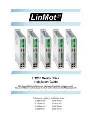
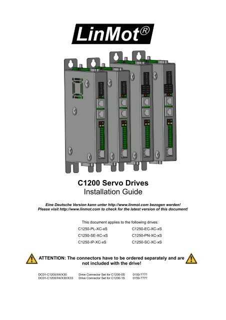
C1200 <strong>Servo</strong> Drives<br />
<strong>Installation</strong> <strong>Guide</strong><br />
Eine Deutsche Version kann unter http://www.linmot.com bezogen werden!<br />
Please visit http://www.linmot.com to check for the latest version of this document!<br />
This document applies to the following drives:<br />
C1250-PL-XC-xS<br />
C1250-EC-XC-xS<br />
C1250-SE-XC-xS<br />
C1250-PN-XC-xS<br />
C1250-IP-XC-xS<br />
C1250-SC-XC-xS<br />
ATTENTION: The connectors have to be ordered separately and are<br />
not included with the drive!<br />
DC01-C1200/X4/X30 Drive Connector Set for C1200-0S 0150-????<br />
DC01-C1200/X4/X30/X33 Drive Connector Set for C1200-1S 0150-????
C1200 <strong>Installation</strong> <strong>Guide</strong> Preliminary<br />
© 2013 NTI AG<br />
This work is protected by copyright.<br />
Under the copyright laws, this publication may not be reproduced or transmitted in any form, electronic or mechanical, including<br />
photocopying, recording, microfilm, storing in an information retrieval system, not even for didactical use, or translating, in whole or in<br />
part, without the prior written consent of NTI AG.<br />
<strong>LinMot</strong>® is a registered trademark of NTI AG.<br />
The information in this documentation reflects the stage of development at the time of press and is therefore without obligation.<br />
NTI AG reserves itself the right to make changes at any time and without notice to reflect further technical advance or product<br />
improvement.<br />
Document version 5.2a / FM, June 2013<br />
Page 2/21 www.<strong>LinMot</strong>.com NTI AG / <strong>LinMot</strong> ®
Preliminary C1200 <strong>Installation</strong> <strong>Guide</strong><br />
Table of Content<br />
1 Important Safety Instructions.........................................................................................4<br />
2 System Overview.............................................................................................................6<br />
3 Interfaces..........................................................................................................................7<br />
4 Functionality and Interfaces...........................................................................................8<br />
5 Software............................................................................................................................8<br />
6 Power Supply and Grounding........................................................................................9<br />
7 Description of the connectors / Interfaces..................................................................10<br />
7.1 X1..............................................................................................................................10<br />
7.2 X2..............................................................................................................................10<br />
7.3 X3..............................................................................................................................11<br />
7.4 X4 .............................................................................................................................12<br />
7.5 X9..............................................................................................................................12<br />
7.6 X13............................................................................................................................13<br />
7.7 X17 - X18..................................................................................................................13<br />
7.8 X19............................................................................................................................14<br />
7.9 X33 ...........................................................................................................................14<br />
7.10 S1 - S2....................................................................................................................14<br />
7.11 S5............................................................................................................................15<br />
7.12 LEDs.......................................................................................................................15<br />
7.13 RT BUS LEDs.........................................................................................................15<br />
8 Error Codes....................................................................................................................16<br />
9 Safety Wiring..................................................................................................................17<br />
10 Physical Dimensions...................................................................................................18<br />
11 Power Supply Requirements......................................................................................19<br />
12 Regeneration of Power................................................................................................19<br />
13 Ordering Information...................................................................................................20<br />
14 International Certifications.........................................................................................20<br />
15 Declaration of Conformity CE-Marking......................................................................21<br />
16 Contact Addresses......................................................................................................22<br />
NTI AG / <strong>LinMot</strong> ® www.<strong>LinMot</strong>.com Page 3/21
C1200 <strong>Installation</strong> <strong>Guide</strong> Preliminary<br />
1 Important Safety Instructions<br />
For your personal safety<br />
Disregarding the following safety measures can lead to severe injury to persons and<br />
damage to material:<br />
• Only use the product as directed.<br />
• Never commission the product in the event of visible damage.<br />
• Never commission the product before assembly has been completed.<br />
• Do not carry out any technical changes on the product.<br />
• Only use the accessories approved for the product.<br />
• Only use original spare parts from <strong>LinMot</strong>.<br />
• Observe all regulations for the prevention of accidents, directives and laws applicable on site.<br />
• Transport, installation, commissioning and maintenance work must only be carried out by qualified<br />
personnel.<br />
• Observe IEC 364 and CENELEC HD 384 or DIN VDE 0100 and IEC report 664 or<br />
DIN VDE 0110 and all national regulations for the prevention of accidents.<br />
• According to the basic safety information, qualified, skilled personnel are persons who are<br />
familiar with the assembly, installation, commissioning, and operation of the product and who<br />
have the qualifications necessary for their occupation.<br />
• Observe all specifications in this documentation.<br />
• This is the condition for safe and trouble−free operation and the achievement of the specified<br />
product features.<br />
• The procedural notes and circuit details described in this documentation are only proposals.<br />
It is up to the user to check whether they can be transferred to the particular applications.<br />
NTI AG / <strong>LinMot</strong> does not accept any liability for the suitability of the procedures and circuit<br />
proposals described.<br />
• <strong>LinMot</strong> servo drives and the accessory components can include live and moving parts (depending on<br />
their type of protection) during operation. Surfaces can be hot.<br />
• Non−authorized removal of the required cover, inappropriate use, incorrect installation or<br />
operation create the risk of severe injury to persons or damage to material assets.<br />
• For more information, please see the documentation.<br />
• High amounts of energy are produced in the drive. Therefore it is required to wear personal<br />
protective equipment (body protection, headgear, eye protection, hand guard).<br />
Application as directed<br />
• drives are components which are designed for installation in electrical systems or machines. They<br />
are not to be used as domestic appliances, but only for industrial purposes according to EN<br />
61000−3−2.<br />
• When drives are installed into machines, commissioning (i.e. starting of the operation as directed) is<br />
prohibited until it is proven that the machine complies with the regulations of the EC Directive<br />
98/37/EC (Machinery Directive); EN 60204 must be observed.<br />
• Commissioning (i.e. starting of the operation as directed) is only allowed when there is compliance<br />
with the EMC Directive (2004/108/EC).<br />
• The technical data and supply conditions can be obtained from the nameplate and the<br />
documentation. They must be strictly observed.<br />
Transport, storage<br />
• Please observe the notes on transport, storage, and appropriate handling.<br />
• Observe the climatic conditions according to the technical data.<br />
Page 4/21 www.<strong>LinMot</strong>.com NTI AG / <strong>LinMot</strong> ®
Preliminary C1200 <strong>Installation</strong> <strong>Guide</strong><br />
<strong>Installation</strong><br />
• The drives must be installed and cooled according to the instructions given in the corresponding<br />
documentation.<br />
• The ambient air must not exceed degree of pollution 2 according to EN 61800−5−1.<br />
• Ensure proper handling and avoid excessive mechanical stress. Do not bend any components and<br />
do not change any insulation distances during transport or handling. Do not touch any electronic<br />
components and contacts.<br />
• drives contain electrostatic sensitive devices which can easily be damaged by inappropriate<br />
handling. Do not damage or destroy any electrical components since this might endanger your<br />
health!<br />
Electrical connection<br />
• When working on live drives, observe the applicable national regulations for the prevention of<br />
accidents.<br />
• The electrical installation must be carried out according to the appropriate regulations (e.g. cable<br />
cross−sections, fuses, PE connection). Additional information can be obtained from the<br />
documentation.<br />
• This product can cause high-frequency interferences in non industrial environments<br />
which can require measures for interference suppression.<br />
Operation<br />
• If necessary, systems including drives must be equipped with additional monitoring and protection<br />
devices according to the valid safety regulations (e.g. law on technical equipment, regulations for the<br />
prevention of accidents). The drives can be adapted to your application. Please observe the<br />
corresponding information given in the documentation.<br />
• After the drive has been disconnected from the supply voltage, all live components and power<br />
connections must not be touched immediately because capacitors can still be charged. Please<br />
observe the corresponding stickers on the drive. All protection covers and doors must be shut during<br />
operation.<br />
Protection of persons<br />
• Before working on the drive, check that no voltage is applied to the power terminals:<br />
• The power terminals Ph1+, Ph1-, Ph2+, Ph2- and PWR+ remain live for at<br />
least 5 minutes after disconnecting from the power supplies.<br />
• The heat sink of the drive has an operating temperature of > 80 °C: Contact with the<br />
heat sink results in burns.<br />
NTI AG / <strong>LinMot</strong> ® www.<strong>LinMot</strong>.com Page 5/21
C1200 <strong>Installation</strong> <strong>Guide</strong> Preliminary<br />
2 System Overview<br />
Typical <strong>Servo</strong> System C12x0-XX: <strong>Servo</strong> Drive, Motor and Power Supply.<br />
Page 6/21 www.<strong>LinMot</strong>.com NTI AG / <strong>LinMot</strong> ®
Preliminary C1200 <strong>Installation</strong> <strong>Guide</strong><br />
3 Interfaces<br />
C12x0-xx-xx-xS-xxx<br />
NTI AG / <strong>LinMot</strong> ® www.<strong>LinMot</strong>.com Page 7/21
C1200 <strong>Installation</strong> <strong>Guide</strong> Preliminary<br />
4 Functionality and Interfaces<br />
C1250-PL-XC-0S<br />
C1250-PN-XC-0S<br />
C1250-SC-XC-0S<br />
C1250-IP-XC-0S<br />
C1250-EC-XC-0S<br />
C1250-SE-XC-0S<br />
C1250-PL-XC-1S<br />
C1250-PN-XC-1S<br />
C1250-SC-XC-1S<br />
C1250-IP-XC-1S<br />
C1250-EC-XC-1S<br />
C1250-SE-XC-1S<br />
Supply Voltage<br />
Motor Supply 72VDC (24..85VDC) ● ● ● ● ● ● ● ● ● ● ● ●<br />
Logic Supply 24VDC (22...26VDC) ● ● ● ● ● ● ● ● ● ● ● ●<br />
Motor Phase Current (preliminary)<br />
25A peak ● ● ● ● ● ● ● ● ● ● ● ●<br />
Controllable Motors<br />
<strong>LinMot</strong> P01…(Motor Link P) ● ● ● ● ● ● ● ● ● ● ● ●<br />
Selected motors (contact support) ● ● ● ● ● ● ● ● ● ● ● ●<br />
Plug and Play (PnP) Auto Configuration ● ● ● ● ● ● ● ● ● ● ● ●<br />
Command Interface<br />
POWERLINK ● ●<br />
PROFINET ● ●<br />
SERCOS III ● ●<br />
ETHERNET IP ● ●<br />
LinUDP ● ●<br />
ETHERCAT ● ● ● ●<br />
SERCOS over ETHERCAT ● ● ● ●<br />
Programmable Motion Profiles (Curves)<br />
Up to 100 Motion Profiles ● ● ● ● ● ● ● ● ● ● ● ●<br />
Programmable Command Table<br />
Command Table with up to 255 entries ● ● ● ● ● ● ● ● ● ● ● ●<br />
External Position Sensor<br />
Incremental (RS422 up to 25 M counts/s) ● ● ● ● ● ● ● ● ● ● ● ●<br />
Absolute (BiSS) ● ● ● ● ● ● ● ● ● ● ● ●<br />
Configuration Interface<br />
RS232 ● ● ● ● ● ● ● ● ● ● ● ●<br />
Integrated Safety Functions (-1S Option)<br />
STO (2 Safety Relays) ● ● ● ● ● ●<br />
5 Software<br />
The configuration software <strong>LinMot</strong>-Talk is free of charge and can be downloaded<br />
from the <strong>LinMot</strong> homepage.<br />
Page 8/21 www.<strong>LinMot</strong>.com NTI AG / <strong>LinMot</strong> ®
Preliminary C1200 <strong>Installation</strong> <strong>Guide</strong><br />
6 Power Supply and Grounding<br />
In order to assure a safe and error free operation, and to avoid severe<br />
damage to system components, all system components must be well<br />
grounded to protective earth PE. This includes both <strong>LinMot</strong> and all<br />
other control system components on the same ground bus.<br />
The leakage current to earth (PE) is >3.5 mA. According to EN 50178 a<br />
fixed installation is required and a double PE connection is required.<br />
One PE connection is on X30, the second one is an M5 bolt on top of<br />
the housing.<br />
Each system component should be tied directly to the ground bus (star<br />
pattern), rather than daisy chaining from component to component.<br />
(<strong>LinMot</strong> motors are properly grounded through their power cables when<br />
connected to <strong>LinMot</strong> drives.)<br />
NTI AG / <strong>LinMot</strong> ® www.<strong>LinMot</strong>.com Page 9/21
C1200 <strong>Installation</strong> <strong>Guide</strong> Preliminary<br />
7 Description of the connectors / Interfaces<br />
7.1 X1<br />
X1<br />
Motor Phases<br />
PWR+<br />
PGND<br />
Motor Supply: 72VDC nominal, 24...85VDC<br />
Absolute max. Rating: 72VDC +20%.<br />
External Fuse: 16AT / min. 100VDC<br />
If motor supply voltage exceeds 90VDC, the drive will go into error state.<br />
– Use 60/75°C copper conductors only<br />
– Conductor Cross-Section 2.5mm 2 (AWG14) max Length 4m<br />
7.2 X2<br />
X2<br />
Motor Phases<br />
PH1+<br />
PH1-<br />
PH2+<br />
PH2-<br />
<strong>LinMot</strong> Motor:<br />
Motor Phase 1+<br />
Motor Phase 1-<br />
Motor Phase 2+<br />
Motor Phase 2-<br />
red<br />
pink<br />
blue<br />
grey<br />
PE/SCRN<br />
Protective Earth / Shield<br />
- Use 60/75°C copper conductors only<br />
- Conductor cross-section: 0.5 – 2.5mm 2 (depends on Motor current) / AWG 21 -14<br />
Page 10/21 www.<strong>LinMot</strong>.com NTI AG / <strong>LinMot</strong> ®
Preliminary C1200 <strong>Installation</strong> <strong>Guide</strong><br />
7.3 X3<br />
X3<br />
Motor Sensor<br />
<strong>LinMot</strong> Motor:<br />
1<br />
2<br />
3<br />
4<br />
5<br />
6<br />
7<br />
8<br />
9<br />
case<br />
Do not connect<br />
Do not connect<br />
+5VDC<br />
Sensor Sine<br />
Temp In<br />
Do not connect<br />
Do not connect<br />
AGND<br />
Sensor Cosine<br />
Shield<br />
DSUB-9 (f)<br />
Note:<br />
Use +5V (X3.3) and AGND (X3.8) only for motor internal hall sensor supply (max. 100mA).<br />
Cable length < 30m.<br />
Caution:<br />
Do NOT connect AGND (X3.8) to ground or earth!<br />
NTI AG / <strong>LinMot</strong> ® www.<strong>LinMot</strong>.com Page 11/21
C1200 <strong>Installation</strong> <strong>Guide</strong> Preliminary<br />
7.4 X4<br />
X4<br />
Logig Supply / IO Connection<br />
11<br />
10<br />
9<br />
8<br />
7<br />
6<br />
5<br />
4<br />
3<br />
2<br />
1<br />
AnIn- X4.11<br />
AnIn+ X4.10<br />
AnIn X4.9<br />
In X4.8<br />
In X4.7<br />
In X4.6<br />
In X4.5<br />
Out X4.4<br />
Out X4.3<br />
+24VDC Supply<br />
GND Supply<br />
Configurable Analog Input differential (with X4.10)<br />
Configurable Analog Input differential (with X4.11)<br />
Configurable Analog Input single ended<br />
Configurable Input<br />
Configurable Input<br />
Configurable Input<br />
Configurable Input<br />
Configurable Output<br />
Configurable Output<br />
Logic Supply 22-26 VDC<br />
Ground<br />
Spring cage<br />
connector<br />
Inputs (X4.5 .. X4.8):<br />
Outputs (X4.3 & X4.4):<br />
Analog inputs:<br />
24V / 5mA (Low Level: –0.5 to 5VDC, High Level: 15 to 30VDC)<br />
24V / max.100mA, Peak 370mA (will shut down if exceeded)<br />
12 bit A/D converted.<br />
Supply 24V / type. 500mA / max. 2.5A (if all outputs “on” with max. load.)<br />
- Use 60/75°C copper conductors only<br />
- Conductor cross-section max. 1.5mm 2<br />
- Stripping length: 10mm<br />
7.5 X13<br />
X13<br />
External Position Sensor Differential Hall Switches<br />
ABZ with Hall Switches<br />
1<br />
2<br />
3<br />
4<br />
5<br />
6<br />
7<br />
8<br />
case<br />
9<br />
10<br />
11<br />
12<br />
13<br />
14<br />
15<br />
+5V DC<br />
A-<br />
B-<br />
Z-<br />
GND<br />
U-<br />
V-<br />
W-<br />
Shield<br />
A+<br />
B+<br />
Z+<br />
Encoder Alarm<br />
U+<br />
V+<br />
W+<br />
DSUB-15 (f)<br />
Position Encoder Inputs (RS422):<br />
Max. counting frequency: 25 Mcounts/s with quadrature decoding, 40ns edge separation<br />
Differential Hall Switch Inputs (RS422):<br />
Input Frequency:
Preliminary C1200 <strong>Installation</strong> <strong>Guide</strong><br />
7.6 X17 - X18<br />
X17 - X18<br />
RealTime Ethernet 10/100 Mbit/s<br />
X17 RT ETH In<br />
Specification depends on RT-Bus Type. Please refer to according documentation.<br />
X18 RT ETH Out<br />
RJ-45<br />
7.7 X19<br />
X19<br />
System<br />
1<br />
2<br />
3<br />
4<br />
5<br />
6<br />
7<br />
8<br />
case<br />
(Do not connect)<br />
(Do not connect)<br />
RS232 Rx<br />
GND<br />
GND<br />
RS232 Tx<br />
(Do not connect)<br />
(Do not connect)<br />
Shield<br />
RJ-45<br />
Use Adapter cable AC01-RJ45/Df-2.5-RS1 (Art.-No. 0150-2143) for Configuration over RS232.<br />
7.8 X33<br />
X33<br />
Safety Relays (only with the -1S option)<br />
4 / 8<br />
3 / 7<br />
2 / 6<br />
1 / 5<br />
Ksr +<br />
Ksr -<br />
Ksr f+<br />
Ksr f-<br />
Safety Relay 1 / 2 Input positive<br />
Safety Relay 1 / 2 Input negative<br />
Safety Relay 1 / 2 feedback positive<br />
Safety Relay 1 / 2 feedback negative<br />
Spring cage connector<br />
- Use 60/75°C copper conductors only<br />
- Conductor cross-section max. 1.5mm 2<br />
- Stripping length: 10mm<br />
- Never connect the safety relays to the logic supply of the drive!<br />
NTI AG / <strong>LinMot</strong> ® www.<strong>LinMot</strong>.com Page 13/21
C1200 <strong>Installation</strong> <strong>Guide</strong> Preliminary<br />
7.9 S1 - S2<br />
S1 - S2<br />
Address Selectors<br />
S1 (5..8)<br />
Bus ID High (0 … F). Bit 5 is the LSB, bit 8 the MSB.<br />
S2 (1..4)<br />
Bus ID Low (0 … F). Bit 1 is the LSB, bit 4 the MSB.<br />
The use of these switches depends on the type of fieldbus which is used. Please see the corresponding<br />
manual for further information.<br />
7.10 S5<br />
S5<br />
Bootstrap<br />
S5<br />
Bootstrap<br />
7.11 LEDs<br />
LEDs<br />
State Display<br />
Green<br />
Yellow<br />
Yellow<br />
Red<br />
24V Logic Supply OK<br />
Motor Enabled / Error Code Low Nibble<br />
Warning / Error Code High Nibble<br />
Error<br />
7.12 RT BUS LEDs<br />
RT Bus LEDs<br />
RT Bus State Display<br />
Green<br />
Red<br />
OK<br />
Error<br />
The use of these LEDs depends on the type of fieldbus which is used. Please see the corresponding<br />
manual for further information.<br />
Page 14/21 www.<strong>LinMot</strong>.com NTI AG / <strong>LinMot</strong> ®
Preliminary C1200 <strong>Installation</strong> <strong>Guide</strong><br />
8 Error Codes<br />
Error Codes<br />
Error Warn EN Description<br />
Off Warning Operation<br />
Enabled<br />
Normal Operation:<br />
Warnings and operation enabled are displayed.<br />
On<br />
● ~2Hz<br />
0..15 x<br />
Error Code<br />
High Nibble<br />
● ~2Hz<br />
0..15 x<br />
Error Code<br />
Low Nibble<br />
Error:<br />
The error code is shown by a blink code with “WARN” and “EN”.<br />
The error byte is divided into low and high nibble (= 4 bit).<br />
”WARN” and “EN” are blinking together.<br />
The error can be acknowledged.<br />
(e.g.: WARN blinks 3x, EN blinks 2x; Error Code = 32h)<br />
● ~2Hz<br />
● ~2Hz<br />
0..15 x<br />
Error Code<br />
High Nibble<br />
● ~2Hz<br />
0..15 x<br />
Error Code<br />
Low Nibble<br />
Fatal Error:<br />
The error code is shown by a blink code with “WARN” and “EN”.<br />
The error byte is divided into low and high nibble.<br />
”WARN” and “EN” are blinking together.<br />
Fatal errors can only be acknowledged by a reset or power cycle.<br />
(e.g.: WARN blinks 3x, EN blinks 2x; Error Code = 32h)<br />
● ~4Hz<br />
● ~2Hz<br />
0..15 x<br />
Error Code<br />
High Nibble<br />
● ~2Hz<br />
0..15 x<br />
Error Code<br />
Low Nibble<br />
System Error:<br />
Please reinstall firmware or contact support.<br />
● ~0.5Hz ● ~0.5Hz On Signal Supply 24V too low:<br />
The error and warn LEDs blink alternating if the signal supply +24V (X4.2) is<br />
less than 18VDC.<br />
Off M●●● ●M●● Plug&Play Communication Active<br />
This sequence (Warn on, then En on, then both off, complete sequence of the<br />
4 states ca. 1Sec) signalizes the state when the plug and play parameters are<br />
being read from the motor.<br />
The meaning of the error codes can be found in the<br />
Usermanual_MotionCtrl_Software_SG5 and the user manual of the installed<br />
interface software. These documents are provided together with <strong>LinMot</strong>-Talk<br />
configuration software and can be downloaded from www.linmot.com.<br />
NTI AG / <strong>LinMot</strong> ® www.<strong>LinMot</strong>.com Page 15/21
C1200 <strong>Installation</strong> <strong>Guide</strong> Preliminary<br />
9 Safety Wiring<br />
The C1200 drives with the -1S option have internal safety functions:<br />
Two Safety relays Ksr in series, which support the supply voltage for the motor<br />
drivers. There are also two feedback contacts for each relay.<br />
To enable the -1S drives both relays have to be switched on.<br />
Minimal wiring:<br />
- Connect X33.8 and X33.4 to 24VDC (from safety)<br />
- Connect X33.7 and X33.3 to GND (from safety)<br />
Attention: Never connect X33.8 and X33.4 to the logic supply of X4!<br />
If an overvoltage protection is needed, it must be provided externally and<br />
sized according the safety circuit of the machine!<br />
Attention: The drop out time of the relays is depending on the external circuitry!<br />
Safety Relay Ksr<br />
Nominal voltage<br />
24 VDC<br />
Min. pick-up voltage at 20°C ≤ 16.8V<br />
Drop-out voltage at 20°C<br />
Drop-out time (no protection circuit)<br />
≥ 2.4 V<br />
Typ. 3ms<br />
Coil resistance at 20°C 2'100 Ω ± 10%<br />
Type<br />
Contact lifetime<br />
Manufacturer and type<br />
EN 50205, type A<br />
> 10'000'000<br />
Elesta relays / SIS112 24VDC<br />
Drive Classification according EN ISO 13849-1 (safety of machinery) (preliminary)<br />
Category cat = 3<br />
Performance Level<br />
PL = d<br />
Diagnostic Coverage<br />
DC = high<br />
Mean Time to hazardous failure of one channel MTTFd = high<br />
Page 16/21 www.<strong>LinMot</strong>.com NTI AG / <strong>LinMot</strong> ®
Preliminary C1200 <strong>Installation</strong> <strong>Guide</strong><br />
10 Physical Dimensions<br />
C1200 Series single axis drive C12xx-xx-XC-0S C12xx-xx-XC-1S<br />
Width mm (in) 25.3 (1.0)<br />
Height mm (in) 166 (6.54) 176 (6.93)<br />
Height with fixings mm (in) 206 (8.11) 216 (8.5)<br />
Depth mm (in) 106 (4.17)<br />
Weight g (lb) 630 (1.4) 700 (1.54)<br />
Mounting<br />
2 x M5<br />
Case IP 20<br />
Storage Temperature °C -25…40<br />
Transport Temperature °C -25…70<br />
Operating Temperature °C 0…40<br />
Relative humidity<br />
Pollution<br />
IEC/EN<br />
60664-1<br />
95% (non-condensing)<br />
Pollution degree 2<br />
Shock resistance (16ms) -1S option 3.5g<br />
Vibration resistance (10-200Hz) -1S option 1g<br />
Max. Case Temperature °C 90<br />
Max. Power Dissipation W ???<br />
Mounting place<br />
Mounting position<br />
In the control cabinet<br />
vertical<br />
Distance between Drives mm (in) Without Power Derating:<br />
20 (0.8) horizontal / 50 (2) vertical<br />
With Power Derating:<br />
5 (0.2) horizontal / 20 (0.8) vertical<br />
NTI AG / <strong>LinMot</strong> ® www.<strong>LinMot</strong>.com Page 17/21
C1200 <strong>Installation</strong> <strong>Guide</strong> Preliminary<br />
11 Power Supply Requirements<br />
Motor Power Supply<br />
The calculation of the needed power for the Motor supply is depending on the<br />
application and the used motor. The nominal supply voltage is 72- 80 VDC. The<br />
possible range is from 24 to 85VDC, for UL from 30 to 85 VDC.<br />
ATTENTION:<br />
The motor supply can rise up to 95 VDC when braking.<br />
This means that everything connected to that power supply needs a<br />
voltage rating of 100 VDC. (Additional capacitors, etc...). Due to high<br />
braking voltage and sudden load variations of linear motor<br />
applications,<br />
only specially designed power supplies can be used.<br />
Signal Power Supply<br />
The logic supply needs a regulated power supply of a nominal voltage of 24 VDC.<br />
The voltage must be between 22 and 26 VDC.<br />
Current consumption:<br />
min. 0.5A<br />
typ. 1.5A<br />
max. 2.5A<br />
(no load on the outputs)<br />
(all 10 outputs “on” with 100mA load and /Break with no load)<br />
(all 10 outputs “on” with 100mA load and /Break with 1A load)<br />
Do not connect the safety relays to the 24VDC Signal Supply!<br />
Use a separate power supply for the safety circuit!<br />
12 Regeneration of Power<br />
Connect an additional capacitor to the motor power supply. It is recommended to<br />
use a capacitor >= 10’000 μF<br />
(install capacitor close to the drive supply!)<br />
Page 18/21 www.<strong>LinMot</strong>.com NTI AG / <strong>LinMot</strong> ®
Preliminary C1200 <strong>Installation</strong> <strong>Guide</strong><br />
13 Ordering Information<br />
Item Description Art. Nr.<br />
C1250-PL-XC-0S POWERLINK Drive (72V/25A) 0150-1885<br />
C1250-SE-XC-0S SERCOS over ETHERCAT Drive (72V/25A) 0150-1897<br />
C1250-IP-XC-0S ETHERNET IP Drive (72V/25A) 0150-1886<br />
C1250-EC-XC-0S ETHERCAT Drive (72V/25A) 0150-1884<br />
C1250-PN-XC-0S PROFINET Drive (72V/25A) 0150-1888<br />
C1250-SC-XC-0S SERCOS III Drive (72V/25A) 0150-1887<br />
C1250-PL-XC-1S POWERLINK Drive (72V/25A/STO) 0150-2347<br />
C1250-SE-XC-1S SERCOS over ETHERCAT Drive (72V/25A/STO) 0150-2350<br />
C1250-IP-XC-1S ETHERNET IP Drive (72V/25A/STO) 0150-2346<br />
C1250-EC-XC-1S ETHERCAT Drive (72V/25A/STO) 0150-2345<br />
C1250-PN-XC-1S PROFINET Drive (72V/25A/STO) 0150-2348<br />
C1250-SC-XC-1S SERCOS III Drive (72V/25A/STO) 0150-2349<br />
RS232 PC config. Cable 2.5m For E1200 / <strong>E1400</strong> 0150-2143<br />
ATTENTION: The connectors have to be ordered separately and are not<br />
included with the drive!<br />
14 International Certifications<br />
Certifications<br />
Europe<br />
See chapter “15 Declaration of Conformity CE-Marking“<br />
UR<br />
UL508C recognition pending<br />
NTI AG / <strong>LinMot</strong> ® www.<strong>LinMot</strong>.com Page 19/21
C1200 <strong>Installation</strong> <strong>Guide</strong> Preliminary<br />
15 Declaration of Conformity CE-Marking<br />
Manufacturer: NTI AG / <strong>LinMot</strong> ®<br />
Products:<br />
Haerdlistrasse 15<br />
8957 Spreitenbach<br />
Switzerland<br />
Tel.: +41 (0)56 419 91 91<br />
Fax: +41 (0)56 419 91 92<br />
<strong>LinMot</strong> ® drives<br />
Type Art.-No. Type Art-No. Type Art.-No.<br />
C1250-IP-XC-0S 0150-1886 C1250-PL-XC-0S 0150-1885 C1250-SE-XC-0S 0150-1897<br />
C1250-PN-XC-0S 0150-1888 C1250-SC-XC-0S 0150-1887 C1250-EC-XC-0S 0150-1884<br />
C1250-IP-XC-1S 0150-2346 C1250-PL-XC-1S 0150-2347 C1250-SE-XC-1S 0150-2350<br />
C1250-PN-XC-1S 0150-2348 C1250-SC-XC-1S 0150-2349 C1250-EC-XC-1S 0150-2345<br />
The product must be mounted and used in strict accordance with the installation instructions<br />
contained within the installation guide, a copy of which may be obtained from NTI Ltd.<br />
I declare that as the authorized representative, the above information in relation to the<br />
supply/manufacture of this product is in conformity with the stated standards and other related<br />
documents in compliance with the protection requirements of the Electromagnetic Compatibility<br />
(EMC) Directive 2004/108/EC and Safety tests according to the 2006/95/EC harmonized standard<br />
EN 50371: 2002.<br />
Standards Complied with:<br />
EN 61000-6-2: 2005<br />
Immunity for industrial environments<br />
EN 61000-4-2 Class B and FS Electrostatic discharge immunity (ESD)<br />
EN 61000-4-3 Class A and FS Radiated electromagnetic field immunity<br />
EN 61000-4-4 Class B and FS Fast transients / burst immunity (EFT)<br />
EN 61000-4-5 Class B and FS Slow transients immunity (Surge)<br />
EN 61000-4-6 Class A and FS Conducted radio frequency immunity<br />
EN 61000-4-8 Class A and FS Power frequency magnetic field immunity<br />
EN 61326-3-1 FS EMC immunity (functional safety)<br />
EN 61000-6-4: 2007<br />
Emission for industrial environments<br />
EN 55022 Class A Stationary interference voltage AC mains<br />
EN55022 Class A Stat. Asym. Interference current on Telco lines<br />
EN 55022 Class A Radiated Emission<br />
EN 61326-3-1:2008<br />
EN 50371<br />
EN 5022<br />
EN 5011<br />
CISPR 22: 2005<br />
Company: NTI Ltd.<br />
Spreitenbach, June 25, 2013<br />
Functional Safety<br />
Human exposure to electromagnetic fields<br />
Radio disturbance (IT equipment)<br />
Radio disturbance (ISM)<br />
Radio disturbance (IT equipment)<br />
-----------------------------------------------------------<br />
R. Rohner / CEO NTI AG<br />
Page 20/21 www.<strong>LinMot</strong>.com NTI AG / <strong>LinMot</strong> ®
Preliminary C1200 <strong>Installation</strong> <strong>Guide</strong><br />
16 Contact Addresses<br />
SWITZERLAND<br />
NTI AG<br />
Haerdlistr. 15<br />
CH-8957 Spreitenbach<br />
Sales and Administration: +41-(0)56-419 91 91<br />
office@linmot.com<br />
Tech. Support: +41-(0)56-544 71 00<br />
support@linmot.com<br />
Tech. Support (Skype) :<br />
skype:support.linmot<br />
Fax: +41-(0)56-419 91 92<br />
Web:<br />
http://www.linmot.com/<br />
USA<br />
<strong>LinMot</strong>, Inc.<br />
204 E. Morrissey Dr.<br />
Elkhorn, WI 53121<br />
Sales and Administration: 877-546-3270<br />
262-743-2555<br />
Tech. Support: 877-804-0718<br />
262-743-1284<br />
Fax: 800-463-8708<br />
262-723-6688<br />
E-Mail:<br />
Web:<br />
us-sales@linmot.com<br />
http://www.linmot-usa.com/<br />
Please visit http://www.linmot.com/ to find the distributor closest to you.<br />
Smart solutions are…<br />
NTI AG / <strong>LinMot</strong> ® www.<strong>LinMot</strong>.com Page 21/21