Mech 10
Mech 10
Mech 10
You also want an ePaper? Increase the reach of your titles
YUMPU automatically turns print PDFs into web optimized ePapers that Google loves.
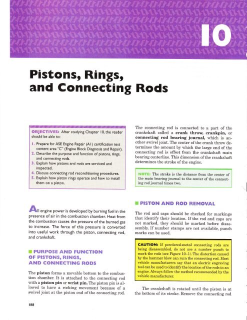
Pistons, Rihgsr<br />
and Connecting Rods<br />
OBf ECTIVES! After studying Chapter <strong>10</strong>, the reader<br />
should be able to:<br />
| . Prepare for ASE Engine Repair (A | ) certification test<br />
content area"C" (Engine Block Diagnosis and Repair).<br />
2. Describe the purpose and function of pistons, rings,<br />
and connecting rods.<br />
_<br />
3. Explain how pistons and rods are serviced and<br />
inspected.<br />
4. Discuss connecting rod reconditioning procedures.<br />
5. Explain how piston rings operate and how to install<br />
them on a piston.<br />
The connecting rod is connected to a part of the<br />
crankshaft called a crank throw, crankpin, or<br />
connecting rod bearing journal, which is another<br />
swivel joint. The center of the crank throw determines<br />
the amount by which the large end of the<br />
connecting rod is offset from the crankshaft main<br />
bearing centerline. This dimension of the crankshaft<br />
determines the stroke of the engine.<br />
S#{gY&, The stroke is the distance from the center of<br />
the main bearing journal to the center of the connecting<br />
rod journal times two.<br />
ffi PISTON AND ROD REMOVAT<br />
Idfll engine power is developed by burning fuel in the<br />
presence of air in the combustion chamber. Heat from<br />
the combustion causes the pressure of the burned gas<br />
to increase. The force of this pressure is converted<br />
into useful work through the piston, connecting rod,<br />
and crankshaft.<br />
ffi PURPOSE AND FUNCTION<br />
oF ptsToNs, RtNGs,<br />
AND COI.INECTING RODS<br />
The piston forms a movable bottom to the combustion<br />
chamber. It is attached to the connecting rod<br />
with a piston pin or wrist pin. The piston pin is aIlowed<br />
to have a rocking movement because of a<br />
swivel joint at the piston end of the connecting rod.<br />
The rod and caps should be checked for markings<br />
that identify their location. If the rod and caps are<br />
not marked, they should be marked before disassembly.<br />
If number stamps are not available, punch<br />
marks can be used.<br />
CAUTION: If powdered-metal connecting rods are<br />
being disassembled, do not use a number punch to<br />
mark the rods (see Figure <strong>10</strong>-1). The distortion caused<br />
by the hammer blow can ruin the connecting rod. Most<br />
vehicle manufacturers say that an electric engraving<br />
tool can be used to identify the location ofthe rods in an<br />
engine. Always follow the method recommended bv the<br />
vehicle manufacturer.<br />
The crankshaft is rotated until the piston is at<br />
the bottom of its stroke. Remove the connecting rod<br />
188
Pistons, Rings, and Connecting Rods<br />
t89<br />
Figure l0-2 A high-performance piston with valve reliefs<br />
machined into the head of the piston to provide for valve<br />
ctearance.<br />
Figure l0-l Powdered metal connecting rods can be<br />
identified by their smooth appearance.<br />
nuts or cap screws and remove the connecting rod<br />
cap. Place protective covers over the connecting rod<br />
bolt threads before pushing the piston/rod assembly<br />
out of the engine through the top of the cylinder. The<br />
protectors help protect the crankshaft journal from<br />
possible damage.<br />
ffi PtsToNs<br />
Recesses machined or cast into the tops of the pistons<br />
for valve clearance are commonly called eyebrows.<br />
These recesses are also called valve reliefs<br />
or valve pockets. The depth of the eyebrows has a<br />
major effect on the compression ratio and is necessary<br />
to provide clearance for the valves if the timing<br />
belt of an overhead camshaft engine should break.<br />
See Figures <strong>10</strong>-2 and <strong>10</strong>-3.<br />
Piston ring grooves are located between the piston<br />
head and skirt. The width of the grooves, the<br />
width of the lands between the ring grooves, and the<br />
Figure | 0-3 Another style of piston with a recessed<br />
head to not only provide valve clearance but also control<br />
comoression ratio.<br />
number of rings are major factors in determining<br />
minimum piston height. The outside diameter of the<br />
Iands is about 0.020 to 0.040 in. (0.5 to 1.0 mm)<br />
smaller than the skirt diameter. See Figure <strong>10</strong>-4.<br />
See Figure <strong>10</strong>-5 for an example of piston diameter<br />
being measured. Always check the service manual<br />
for the exact location and specifrcations for the<br />
piston being checked.
t90<br />
CHAPTER IO<br />
Figure I0-4 A typical piston illustrating the various parts<br />
and the names.<br />
Figure | 0-6 The piston rings must have the specified<br />
side and back clearance.<br />
PISTON PIN<br />
S}IAPE AT ROOM<br />
TEIiPERATURE<br />
Pt$TOil 80SS<br />
Figure l0-5 All pistons are measured across the skirt.<br />
F##gA; Some engines, such as the Honda high-fueleconomy<br />
engine, use pistons with two rings: one compression<br />
ring and one oil ring.<br />
The piston ring groove must be deep enough to<br />
prevent the ring from hitting the base of the<br />
groove when the ring is pressed in so that it is flat<br />
with the land face. This is called back spacing.<br />
See Figure <strong>10</strong>-6.<br />
Cam Ground Pistons<br />
Aluminum pistons expand when hot.To control the expansion<br />
of the piston, the skirt of the piston is cam<br />
SIIAPE AT OPERATII{G<br />
TET'PERATURE IN A<br />
RUNI{|NG ENGIf'|E<br />
Figure l0-7 Pistons are often cam-ground to produce the<br />
elliptical shape when the piston is at room temperature.<br />
ground. With this design, the piston thrust surfaces<br />
closely fit the cylinder, and the piston pin boss diameter<br />
is fitted loosely. As the cam ground piston is heated,<br />
it expands along the piston pin so that it becomes<br />
nearly round at its normal operating temperatures. A<br />
cam ground piston skirt is illustrated in Figure <strong>10</strong>-7.
Pistons, Rings, and Connecting Rods<br />
t9l<br />
Piston Weight ls lmportantl<br />
All pistons in an engine should weigh the same to help<br />
ensure a balanced engine. Piston weight becomes a factor<br />
whenever changing pistons. Most aluminum pistons<br />
range in weight from l0 to 30 ounces (280 to 850<br />
grams) (l oz. : 28.35 g). A typical paper clip weighs one<br />
grom. If the cylinder has been bored, larger replacement<br />
pistons are obviously required. lf the replacement pistons<br />
weigh more, this puts additional inertia loads on<br />
the rod bearings.<br />
FORGED 2OOO<br />
CAUTION: Some less expensive replacement pistons<br />
are a great deal heavier than the stock pistons, even in the<br />
same stock bore size. lf these heavy pistons are used, connecting<br />
rod bearing failure can occur.<br />
For the same reason, if one piston is being replaced,<br />
all pistons should be replaced or at least checked and<br />
corrected to ensure they have the same weight.<br />
Hypereutectic Cast Pistons<br />
A standard cast-aluminum piston contains aboutg7o<br />
to l27o silicon and is called a eutectic piston. To add<br />
strength, the silicon content is increased to about<br />
167o, and the resulting piston is called a hypereutectic<br />
piston. Other advantages of a hypereutectic<br />
piston are its 257a weight reduction and lower expansion<br />
rate. The disadvantage ofhypereutectic pistons<br />
is their higher cost, because they are more difficult<br />
to cast and machine.<br />
Hypereutectic pistons are commonly used in the<br />
aftermarket and as original equipment in many turbocharged<br />
and supercharged engines.<br />
Forged Pistons<br />
High-performance engines need pistons with added<br />
strength. They use impact-extruded forged pistons<br />
whose design allows for great strength and is used<br />
whenever the engine is going to be exposed to extreme<br />
operation conditions such as racing. A forged<br />
piston is denser than a cast piston and conducts heat<br />
faster so it operates cooler. See Figure <strong>10</strong>-8.<br />
Piston Skirt Finish<br />
For maximum life, the piston skirt surface finish is<br />
important. Turned grooves or waves 0.0005 inch<br />
(0.0125 millimeter) deep on the surface of some piston<br />
skirts produce a finish that will carry oil for lu-<br />
Figure l0-8 Notice the temperature difference between<br />
a forged piston and a cast piston.<br />
brication. Other piston skirts are relatively smooth.<br />
A thin tin-plated surface (approximately 0.00005<br />
inch or 0.00125 millimeter thick) is also used on<br />
some aluminum pistons to help reduce scuffing and<br />
scoring during occasional periods of minimum lubrication.<br />
Some pistons have a Teflon coating on the<br />
skirt to prevent scuffr.ng, as shown in Figure <strong>10</strong>-9.<br />
Piston Pins<br />
CAST<br />
Piston pins are used to attach the piston to the connecting<br />
rod. Piston pins are also known as gudgeon<br />
pins (a British term). The piston pin transfers<br />
the force produced by combustion chamber<br />
pressures and piston inertia to the connecting rod.<br />
The piston pin is made from high-quality steel in<br />
the shape of a tube to make it both strong and light.<br />
See Figure <strong>10</strong>-<strong>10</strong>.
192 CHAPTER IO<br />
TAPSRED BOBS<br />
STRAIGHT BORE<br />
Figure l0-<strong>10</strong> Cross-sectional piston pins. Most piston<br />
pins are hollow to reduce weight and have a straight bore.<br />
Some pins use a tapered bore to add strength.<br />
Figure l0-9 A low-friction moly coating on the skirt of<br />
this piston helps prevent piston scuffing when the engine is<br />
cold.<br />
t--<br />
How Can a Piston Have<br />
a Negative Clearancet<br />
MAJOR<br />
THRUST -------*<br />
SURFACE<br />
The specification for some DaimlerChrysler engines includes<br />
a piston-to-cylinder wall clearance as small as<br />
0.0005 in. negotive. This means that the piston is larger<br />
than the bore! How is that possible? According to DaimlerChrysler,<br />
a service technician cannot accurately measure<br />
the diameter of the piston and determine the piston-to-cylinder<br />
clearance due to the application of the<br />
antifriction coating on the sl
Pistons, Rings, and Connecting Rods<br />
t93<br />
BTDC<br />
COMPRESSION<br />
STROKE<br />
Figure l0-12 Enginerotationandrodangleduringthepowerstrokecausestheengine<br />
to press harder against one side of the cylinder, creating a major thrust surface. In this<br />
clockwise-rotating engine, as viewed from the front of the engine, the maior thrust<br />
surface is on the left side.<br />
by the pin offset. As the piston moves up in the cylinder<br />
on the compression stroke, it is riding against the<br />
minor thrust surface. When compression pressure becomes<br />
high enough, the greater head area on the minor<br />
side causes the piston to cock slightly in the cylinder.<br />
This keeps the top of the minor thrust surface on<br />
the cylinder. It forces the bottom of the major thrust<br />
surface to contact the cylinder wall. As the piston approaches<br />
top center, both thrust surfaces are in contact<br />
with the cylinder wall. When the crankshaft<br />
crosses over top center, the force on the connecting<br />
rod moves the entire piston toward the major thrust<br />
surface. The lower portion of the major thrust surface<br />
has already been in contact with the cylinder wall.<br />
The rest of the piston skirt wipes into full contact just<br />
after the crossover point, thereby controlling piston<br />
slap. This action is illustrated in Figure <strong>10</strong>-12.<br />
ru#Tffic Not all piston pins are offset. In fact, many engines<br />
operate without the offset to help reduce friction<br />
and improve power and fuel economy.<br />
Piston Pin Retaining Methods<br />
It is necessary to retain or hold piston pins so that<br />
they stay centered in the piston. If piston pins were<br />
not retained, they would move endwise and groove<br />
the cylinder wall. Piston pins are retained in one of<br />
two common ways. The piston pin may be full floating,<br />
with some type of stop located at each end. Fullfloating<br />
piston pins in automotive engines are re-<br />
What's That Knocking Noiset<br />
A worn piston pin or an enlarged piston pin hole in the<br />
piston causes a double knock sound when the engine is<br />
running. Unlike other knocking sounds, the sound of a<br />
worn piston pin will not disappear when the cylinder is<br />
grounded out and prevented from firing. Obviously, the<br />
engine will have to be disassembled and replacement piston(s)<br />
installed to correct the knocking noise.<br />
tained by lock rings located in grooves in the piston<br />
pin hole at the ends of the piston pin. See Figures<br />
<strong>10</strong>-13 and <strong>10</strong>-14.<br />
The modern method of retaining the piston pin<br />
in the connecting rod is to make the connecting rod<br />
hole slightly smaller than the piston pin. The pin is<br />
installed by heating the rod to expand the hole or by<br />
pressing the pin into the rod. This press or shrink fit<br />
is called an interference fit.<br />
ffi COMPRESSION RllrlGS<br />
A compression ring is designed to form a seal between<br />
the moving piston and the cylinder wall. Combustion<br />
chamber pressure during the compression, power, and
194 CHAPTER IO<br />
CIRCLIP<br />
r<br />
='., ,e".<br />
€a**,<br />
MACHINED SLOT<br />
Figure l0-13 Circlips or snap rings hold full-floating<br />
piston pins in place.<br />
Big Problem, No Noise<br />
Sometimes the piston pin can "walk" off the center of the<br />
piston and score the cylinder wall. This scoring is often<br />
not noticed because this type of wear does not create<br />
noise. Because the piston pin is below the piston rings, little<br />
combustion pressure is lost past the rings until the<br />
groove worn by the piston pin has worn the piston rings.<br />
Troubleshooting the exact cause ofthe increased oil<br />
consumption is difficult because the damage done to the<br />
oil control rings by the groove usually affects only one<br />
cylinder.<br />
Often, compression tests indicate good compression<br />
because the cylinder seals, especially at the top. More<br />
than one technician has been surprised to see the cylinder<br />
gouged by a piston pin when the cylinder head is removed<br />
for service. ln such a case, the cost of the engine<br />
repair immediately increases far beyond that of normal<br />
cylinder head service.<br />
Figure !8*[4 This high-performance connecting rod uses<br />
a bronze bushing in the small end of the rod and an oil<br />
hole to allow oil to reach the full-floating pin.<br />
COMPRSS$IOtt, FORCE<br />
,*,+-+ P ,-*.*\<br />
U\a\L\&l\bb \<br />
exhaust strokes is applied to the top and back ofthe<br />
ring. This pressure will add the force to the ring that<br />
is required to seal the combustion chamber during<br />
these strokes. Figure <strong>10</strong>-15 illustrates how the combustion<br />
chamber pressure adds force to the ring.<br />
Top compression rings are usually rectangular<br />
or barrel shaped. The barrel is 0.0003 inch per<br />
0.<strong>10</strong>0 inch (0.0076 millimeter per 0.254 millimeter)<br />
of the piston ring width. See Figure <strong>10</strong>-16. A piston<br />
ring with a taper face would contact the cylinder<br />
wall at the lower edge of the piston ring. See Figure<br />
l-0-17. Positive twist will give the same wall contact<br />
as the taper-faced ring and will also provide a<br />
Fignrn e lG*[5 Combustion chamber pressure forces the<br />
ring against the cylinder wall and the bottom of the ring<br />
groove. These are the two sealing surfaces that the top<br />
ring must be able to seal for maximum engine power.<br />
line contact seal on the bottom side ofthe groove. By<br />
chamfering the ring's lower inner corner, a reverse<br />
twist is produced. This seals the lower, outer section<br />
of the ring and piston ring groove, thus improving oil<br />
control. Reverse twist rings require a greater taper<br />
face or barrel face to maintain the desired ring-faceto-cylinder-wall<br />
contact. See Figure <strong>10</strong>-18.
Flsi*r-os, Ring:. e;rd C*nn*crir-rg Rnds<br />
t9s<br />
RECTANGULAR<br />
POSIT'VE TORSIOT.IAL<br />
TWIST<br />
BARREL FACE<br />
REVERSE TORSIOIIIAL<br />
TWIST<br />
Figure E ** I 6 The rectangular and the barrel face are the<br />
most commonly used top compression rings because they<br />
provide the best seal.<br />
Figure [&*fl& Torsional twist rings provide better<br />
compression sealing and oil control than regular taper face<br />
rings.<br />
TAP€R FACE<br />
Figara"+: !G:E? The taper face ring provides good oil<br />
control by scraping the cylinder wall. lf this design ring<br />
were accidentally installed upside down, the tapered face<br />
would pump oil into the combustion chamber.<br />
ffi*mg Gap<br />
The piston ring gap will allow some leakage of gases<br />
past the top compression ring. This leakage is useful in<br />
providing pressure on the second ring to develop a dynamic<br />
sealing force. The amount of piston ring gap is<br />
critical. Too much gap will allow excessive blowby, the<br />
leakage of combustion gases past the rings. Too little<br />
gap, on the other hand, will allow the piston ring ends<br />
to butt when the engine is hot. Ring end butting increases<br />
the mechanical force against the cylinder wall,<br />
causing excessive wear and possible engine failure.<br />
Figur* !&*E€ Chromium facing can be seen on the right<br />
side of the sectional view of the piston ring.<br />
materials are present in the air. During manufacture,<br />
the chromium-plated ring is slightly chamfered<br />
at the outer corners. About 0.0004 inch (0.0<strong>10</strong> millimeter)<br />
of chrome is then plated on the ring face.<br />
Chromium-faced rings are prelapped or honed before<br />
they are packaged and shipped to the customer. The<br />
frnished chromium facing is shown in a sectional<br />
view in Figure <strong>10</strong>-19.<br />
#ffinem$aeBE:+ trE1s #F'E ffi**tgs<br />
A chromium facing on cast-iron rings greatly increases<br />
piston ring life, especially where abrasive<br />
Metybd*ffic&#e P$s€*se #€nmgs<br />
Early in the 1960s, molybdenum piston ring faces<br />
were introduced. These rings proved to have good
t96<br />
CHAPTER IO<br />
Gap the Second Ring Wider<br />
Than the Top Ring<br />
In the past, it was standard operating procedure that vehicle<br />
and piston ring manufacturers specified a wider piston<br />
ring gap on the top ring and a narrower gap for the<br />
second compression ring. The reason given was the top<br />
ring was exposed to greater heat and, therefore, would<br />
expand more than the second ring.<br />
Today many vehicle manufacturers, as well as piston<br />
ring manufacturers, are specifying that the second ring<br />
gap should be greater than the top ring gap. The reason<br />
given is that the larger second ring gap prevents combustion<br />
pressure between the rings that can cause the top<br />
ring to be lifted up off the bottom of the ring groove. lf<br />
the top ring is raised up, it cannot properly seal the combustion<br />
gases. With this in mind, many high-performance<br />
engine builders are specifying a standard ring gap for the<br />
top ring and a ring gap of 0.002 to 0.004 in. greater for<br />
the second ring.<br />
service life, especially under scuffing conditions.<br />
Most molybdenum-faced piston rings have a groove<br />
that is 0.004 to 0.008 inch (0.1 to 0.2 millimeter) deep<br />
cut into the ring face. This groove is filled with<br />
molybdenum, using a metallic (or plasma) spray<br />
method, so that there is a cast-iron edge above and<br />
below the molybdenum. A sectional view of a molybdenum-faced<br />
ring is shown in Figure <strong>10</strong>-20.<br />
A molybdenum-faced ring, when used, will be<br />
found in the top groove, and a plain cast-iron or<br />
chromium-faced ring will be found in the second<br />
groove.<br />
Moly-Chrome-Carbide Rings<br />
Rings with a moly-chrome-carbide coating are also<br />
used in some original equipment (OE) and replacement<br />
applications. The coating has properties that<br />
include the hardness of the chrome and carbide<br />
combined with the heat resistance of molybdenum.<br />
Ceramic-coated rings are also used when additional<br />
heat resistance is needed, such as in some heavyduty,<br />
turbocharged, or supercharged engines.<br />
Oil Control Rings<br />
Steel rails with chromium or other types of facings<br />
are used on most oil control rings. The rails are<br />
backed with expanders and separated with a<br />
spacer, seen in Figure <strong>10</strong>-21.<br />
Figure l0-20 Molybdenum facing can be seen on the<br />
right side of the sectional view of the piston ring.<br />
IIiIi<br />
CONNECTIHG RODS<br />
The connecting rod transfers the force and reciprocating<br />
motion of the piston to the crankshaft. The small<br />
end of the connecting rod reciprocates with the piston.<br />
The large end rotates with the crankpin. See Figure<br />
<strong>10</strong>-23. These dynamic motions make it desirable to<br />
keep the connecting rod as light as possible while still<br />
having a rigid beam section. Lightweight rods also reduce<br />
the total connecting rod material cost.<br />
Connecting rods are manufactured by casting,<br />
forging, and powdered (sintered) metal processes.<br />
Forged connecting rods have been used for years and<br />
have a thick parting line along the length of the rod.<br />
They are always used in high-performance engines<br />
and are generally used in heavy-duty engines. The<br />
cost of cast rods is lower than that of forged rods,<br />
both in the initial casting and in the machining. Cast<br />
rods can be identified by a thin parting line along the<br />
length of the rod. Generally, the forging method produces<br />
lighter weight and stronger, but more expensive,<br />
connecting rods.<br />
Powdered Metal Connecting Rods<br />
Some production engines, such as the General Motors<br />
Northstar, have been switched from forged to pow-
Pistons, Rings, and Connecting Rods<br />
t97<br />
Figure l0-2 I This typical three-piece oil control ring uses a hump-type stainless steel<br />
spacer-expander. The expander separates the two steel rails and presses them against<br />
the cylinder wall.<br />
PISTON<br />
CONl'lECllNG<br />
ROD<br />
ROD<br />
SOLT<br />
Figure l0-22 The gapless ring overlaps, while the<br />
conventional ring design uses a gap.<br />
dered metal (PM) rods, which proved to be stronger.<br />
Each ofthe rods is blended into a tapered I-beam section.<br />
The large split-ring form for the crankshaft end<br />
is machined after the cap is assembled on the rod.<br />
:\:'i::l'.:":i-:+::ni:i.:11:.++:=.i::::!iFa!:::::!ilrl=l:€*:=+:i-!:l++E+:=+*q:i*:*;l.:€iigEffiT<br />
I iriri.:T+:t: Most powdered (sintered) metal connecting i<br />
, rods are broken at the parting end ofthe big end ofthe !<br />
i connecting rod. This rough, broken surface helps en- j<br />
: sure a perfect match when the pieces are bolted to- I<br />
, sether' se:-li*:."<br />
1o-?,n- ""..- -" -- " : i<br />
The hole will be a perfect circle. Therefore, the rod<br />
caps must not be interchanged. Assembly bolt holes<br />
are closely reamed in both the cap and connecting<br />
rod to ensure alignment. The connecting rod bolts<br />
Figure l0-23 A typical connecting rod and related<br />
engine parts. The connecting rod is probably the most<br />
highly stressed part in the engine. Combustion forces try<br />
to compress it and when the piston stops at the top of the<br />
cylinder, inertia forces try to pull it apart.<br />
have piloting surfaces that closely frt these<br />
reamed holes.<br />
Connecting Rod Design<br />
In some engines, offset connecting rods provide the<br />
most economical distribution of main bearing space
98<br />
CHAPTER iO<br />
BALANCE<br />
PAD<br />
Figure | 0-24 Most powdered metal cast connecting<br />
rods are broken at the parting line.<br />
and crankshaft cheek clearance. Some V-6 engines<br />
have the connecting rods offset by approximately<br />
0.<strong>10</strong>0 inch (2.54 millimeters).<br />
Connecting rods are made with balancing bosses<br />
so that their weight can be adjusted to specifications.<br />
Some have balancing bosses only on the rod cap. Others<br />
have a balancing boss above the piston as weII.<br />
Some manufacturers put balancing bosses on the<br />
side ofthe rod, near the center ofgravity ofthe connecting<br />
rod. Typical balancing bosses can be seen in<br />
Figure 70-25. Balancing is done on automatic balancing<br />
machines as the final machining operation<br />
before the rod is installed in an ensine.<br />
Connecting Rocl Service<br />
As an engine operates, the forces go through the<br />
large end of the connecting rod. This causes the<br />
crankshaft end opening ofthe rod (eye) to gradually<br />
deform. The large eye of the connecting rod is resized<br />
during precision engine service. See Figure 70-2G.<br />
Step I The parting surfaces of the rod and cap are<br />
smoothed to remove all high spots before resizing.<br />
A couple of thousandths of an inch of metal<br />
is removed from the rod cap parting surface. The<br />
amount removed from the rod and rod cap only<br />
reduces the bore size 0.003 to 0.006 inch (0.08 to<br />
0.15 millimeter).<br />
F{O?S; Powdered metal connecting rods cannot be reconditioned<br />
using this method. Most manufacturers<br />
recommend replacing worn powdered metal connecting<br />
rods.<br />
Figure l0-25 Some connecting rods have balancing<br />
bosses (pads) on each end of the rod.<br />
Step 3 The cap is installed on the rod, and the nuts<br />
or cap screws are properly torqued.<br />
S**p 3 The hole is then bored or honed to be perfectly<br />
round, as shown in Figure <strong>10</strong>-27.<br />
Sf*p 4 The connecting rod is checked for twist (misalignment).<br />
See Figure <strong>10</strong>-28.<br />
ffi PTSTON AND ROD ASSEMBTY<br />
To assemble the piston and rod, the piston pin is put<br />
in one side of the piston. The piston and rod are<br />
placed on a press, using adapters and supports. This<br />
setup is shown in Figure t0-29. The pin is pressed<br />
into the rod until it is centered. The press-fit of the
Pistons, Rings, and Connecting Rods<br />
t99<br />
Figure l0-27 A connecting rod being reconditioned.<br />
SURFACE<br />
PLATE<br />
Figure l0-26 The rod bearing bores normally stretch<br />
from top to bottom causing the rod bearing to wear most<br />
near the parting line.<br />
I<br />
BENO<br />
INDICATOR<br />
The Might-As-Wells<br />
One of the hardest questions a technician or vehicle<br />
owner faces is,"How much work should be done to make<br />
a proper repair without incurring too much cost?" The<br />
technician wants to make a proper repair to prevent an<br />
early failure (and a customer comeback). The vehicle<br />
owner does not want to spend any more than is necessary<br />
for the repair service.<br />
When the engine is disassembled, many small procedures,<br />
such as connecting rod reconditioning, are often<br />
left unperformed because of additional effort and cost.<br />
Connecting rod reconditioning is one of many operations<br />
considered important enough to be included in a proper<br />
engine repair or overhaul. Many engine rebuilders also<br />
recommend replacing all connecting rod bolts whenever<br />
the engine is disassembled. The major expense is removing<br />
the engine from the vehicle; therefore, the technician<br />
"might as well" do a complete and thorough engine service<br />
job and convince the customer that the added expense<br />
of "doing it right" is money well spent.<br />
pin in the small eye of the rod will hold the pin securely<br />
in place during engine operation. In precision<br />
engine shops, the small eye of the connecting rod is<br />
heated before the pin is installed. This causes the rod<br />
eye to expand so that the pin can be pushed into<br />
CONTACT<br />
BAf,S<br />
CONNECTING<br />
ROD<br />
Figure l0-28 A rod alignment fixture being used to<br />
check a connecting rod to see if it is bent or twisted.<br />
place with little force. The pin must be rapidly<br />
pushed into the correct center position.<br />
Full-floating piston pins operate in a bushing in<br />
the small eye of the connecting rod. The full-floating<br />
piston pin is held in place with a lock ring at each<br />
end. The lock rings should always be replaced with<br />
new rings.<br />
There is usually a noteh on the piston head indicating<br />
t}i'e front. Using this will correctly position<br />
the piston pin offset toward the right side of the engine.<br />
The connecting rod identification marks on<br />
pushrod inline engines are normally placed on the<br />
camshaft side.
CHAPTER IO<br />
Figure l0-30 Using a connecting rod bolt stretch gauge<br />
to measure the amount the rod bolt stretches to tighten<br />
the fastener to its ultimate strength.<br />
:#ffd '<br />
Figure l0-29 A press used to remove and install<br />
connecting rods to the pistons.<br />
Use a Rod Bolt Stretch Gauge<br />
When a fastener is torqued to specification, it may or<br />
may not be applying the clamping force that is necessary.<br />
Many high-performance engine builders use a connecting<br />
rod bolt stretch gauge to measure the actual amount the<br />
rod bolt is being stretched. This process results in uniform<br />
clamping force on all connecting rod cap bolts. See<br />
Figure l0-30.
Pistons, Rings, and Connecting Rods 201<br />
lEf ffi<br />
:; $f{{s+ gs1<br />
,.t.,,.<br />
ffi<br />
Lr F<br />
P8-l New piston rings, piston ring expanders, piston<br />
groove cleaner, and a piston ring grinder are all<br />
necessary items to fit piston rings to a particular<br />
P8-2 Remove the old piston rings from the piston<br />
using a piston ring expander tool.<br />
' _ . 'l'<br />
f*! a.<br />
P8-3 Carefully clean the piston ring grooves using a<br />
piston ring groove-cleaning tool.<br />
P8-4 The oil drain holes behind the oil control rings<br />
should be cleaned.<br />
" '+.q.<br />
P8-5 Whenever fitting piston rings to pistons, always<br />
be certain to properly assemble the piston on the<br />
connecting rod. The rod should be marked with its<br />
cylinder position in the engine.<br />
P8-6 Piston rings should be checked for proper size<br />
and application. Consult the instructions for the<br />
meaning of the marks (data) on the rings.
202 CHAPTER IO<br />
*<br />
P8-7 Measure the side clearance between the piston<br />
ring and the piston ring groove using a feeler (thickness)<br />
gauge. Compare the readings to factory specifications<br />
(usually between 0.001 in.-0.003 in.).<br />
P8-8 Insert a piston ring into the proper cylinder and<br />
use a piston upside down to help position the ring<br />
squarely in the cylinder bore.<br />
P8-9 Use a feeler gauge to measure the piston ring<br />
end gap and compare ro the factory specifications<br />
(usually 0.004 in. per inch of bore).<br />
P8- l 0 lf the piston ring end gap is too close, use a<br />
grinder to remove material from the ends of the piston<br />
rings until the proper end gap has been achieved.<br />
P8-l I Carefully install the piston rings onto the piston<br />
using a piston ring expander.<br />
P8-12 Be sure to position the gap of the rings<br />
according to factory recommendations before installing<br />
the piston in the cylinder.
Pistons, Rings, and Connecting Rods 203<br />
T SUMMARY<br />
1. The connecting rods should be marked before disassembly.<br />
2. Pistons are cam ground so that when operating temperature<br />
is reached, the piston will have expanded<br />
enough across the piston pin area to become round.<br />
3. Replacement pistons should weigh the same as the<br />
original pistons to maintain proper engine balance.<br />
4. Some engines have an offset piston pin to help reduce<br />
piston slap when the engine is cold.<br />
5. Piston rings usually include two compression rings at<br />
the top ofthe piston and an oil control ring below the<br />
compression rings.<br />
6. If the ring end gap is excessive, blowby gases can<br />
travel past the rings and into the crankcase.<br />
7. Many piston rings are made of coated cast iron to provide<br />
proper sealing.<br />
8. If the connecting rod is twisted, diagonal wear will be<br />
noticed on the piston skirt.<br />
9. Powdered metal connecting rods are usually broken at<br />
the big end parting line. Because of this rough junction,<br />
powdered metal connecting rods cannot be re-<br />
;;ditloned-they<br />
must be replaced if damaged or<br />
<strong>10</strong>. The piston and the connecting rod must be correctly<br />
assembled according to identifying notches or marks.<br />
r REVTEW QUESTTONS<br />
1. Describe the procedure for correctly removing the piston<br />
and rod assembly from the engine.<br />
2. Why are some piston skirts plated or coated?<br />
3. Describe the effect ofthe piston pin offset as it controls<br />
piston slap.<br />
4. Why is it important to keep the connecting rod cap with<br />
the rod on which it was originally used and to install it<br />
in the correct way?<br />
5. Describe how connecting rods are reconditioned.<br />
6. How is the piston pin installed in the piston and rod assembly?<br />
X ASE CERTIFICATION.TYPE<br />
QUESTTONS<br />
1. Connecting rod caps should be marked (if they were not<br />
marked at the factory) before the piston and connecting<br />
rod assembly is removed from the engine _.<br />
a. Because they are balanced together<br />
b. Because they are machined together<br />
c. To make certain that the heavier rod is<br />
matched to the heavier piston<br />
d. To make certain that the lighter rod is<br />
matched to the lighter piston<br />
2. Many aluminum pistons skirts are plated with _.<br />
a. Tin<br />
b. Lead<br />
c. Antimony<br />
d. Terneplate<br />
3. A hypereutectic piston has<br />
a. A higher weight than a eutectic piston<br />
b. Ahigher silicon content<br />
-.<br />
c. Ahigher tin content<br />
d. Ahigher nickel content<br />
4. Protective covers should be placed over the connecting<br />
rod threads to help prevent damage to the _.<br />
a. Connecting rod<br />
b. Crankshaft<br />
c. Cylinder wall<br />
d. Camshaft<br />
5. Full-floating piston pins are retained by _.<br />
a. Lock rings<br />
b. A drilled hole with roll pin<br />
c. An interference fit between rod and piston pin<br />
d. An interference fit between piston and piston<br />
pin<br />
6. A misaligned connecting rod causes what tlpe of engine<br />
wear?<br />
a. Cylinder taper<br />
b. Barrel-shaped cylinders<br />
c. Ridge wear<br />
d. Angle wear on the piston skirt<br />
7. Piston damage is most likely to be caused by _.<br />
a. Valves hitting the piston head<br />
b. Abnormal combustion<br />
c. Lugging the engine during operation<br />
d. High engine speeds that can break piston<br />
heads<br />
8. The diameter of the piston is measured _.<br />
a. Across the top (head) ofthe piston<br />
b. Across the piston pin<br />
c. Across the thrust surface<br />
d. Between the top and second piston ring<br />
9. Full-floating piston pins use an interference fit between<br />
the piston and the piston pin.<br />
a. True<br />
b. False<br />
<strong>10</strong>. A worn piston pin causes what type of problem?<br />
a. Engine burns an excessive amount of oil (blue<br />
smoke)<br />
b. Engine produces a knocking noise that will<br />
disappear ifthe cylinder is grounded out<br />
c. Engine produces a double knocking noise that<br />
will not disappear if the cylinder is grounded<br />
out<br />
d. Engine knock when cold only


