
Create successful ePaper yourself
Turn your PDF publications into a flip-book with our unique Google optimized e-Paper software.
Computer Sensor<br />
Operation, Diagnosis,<br />
and Service<br />
ffiffi'$ffi4:YfrWffiSa After studying <strong>Ch</strong>apter <strong>26</strong>, the reader<br />
should be able to:<br />
Prepare for ASE Engine Performance (A8)<br />
certification test content area "E" (Computerized<br />
Engine Controls Diagnosis and Repair). Powertrain<br />
Controls Diagnosis)<br />
'fi,, Discuss the operation and testing procedure for an<br />
engine coolant temperature sensor.<br />
.$" Explain how to test an exhaust gas oxygen sensor.<br />
-{. Describe how to test a throttle position sensor.<br />
5. Explain the operation of a mass airflow sensor.<br />
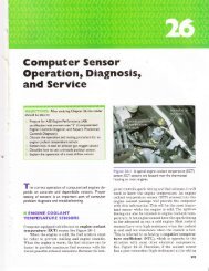
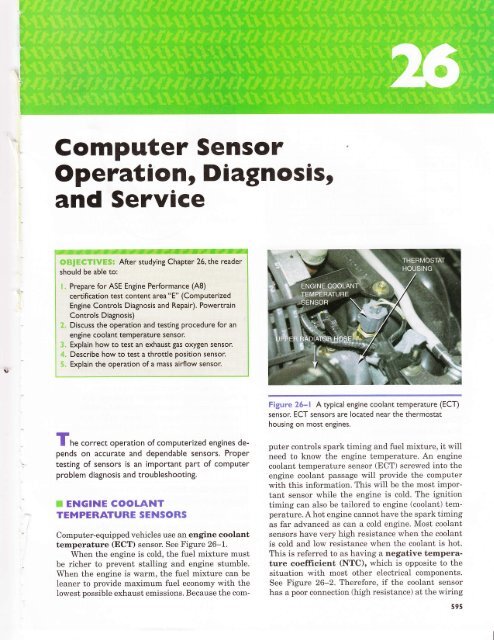
Figure <strong>26</strong>-l A typical engine coolant temperature (ECT)<br />
sensor. ECT sensors are located near the thermostat<br />
housing on most engines.<br />
I he correct operation of computerized engines depends<br />
on accurate and dependable sensors. Proper<br />
testing of sensors is an important part of computer<br />
problem diagnosis and troubleshooting.<br />
ffiffi ENGINE COOLANT<br />
TEMPERATURE SENSORS<br />
Computer-equipped vehicles use an engine coolant<br />
temperature (ECT) sensor. See Figure <strong>26</strong>-1.<br />
When the engine is cold, the fuel mixture must<br />
be richer to prevent stalling and engine stumble.<br />
When the engine is warm, the fuel mixture can be<br />
leaner to provide maximum fuel economy with the<br />
lowest possible exhaust emissions. Because the com-<br />
puter controls spark timing and fuel mixture, it will<br />
need to know the engine temperature. An engine<br />
coolant temperature sensor (ECT) screwed into the<br />
engine coolant passage will provide the computer<br />
with this information. This will be the most important<br />
sensor while the engine is cold. The ignition<br />
timing can also be tailored to engine (coolant) temperature.<br />
A hot engine cannot have the spark timing<br />
as far advanced as can a cold engine. Most coolant<br />
sensors have very high resistance when the coolant<br />
is cold and low resistance when the coolant is hot.<br />
This is referred to as having a negative temperature<br />
coefficient (NTC), which is opposite to the<br />
situation with most other electrical components.<br />
See Figure <strong>26</strong>-2. "Iherefore, if the coolant sensor<br />
has a poor connection (high resistance) at the wiring<br />
595
596 CHAPTER <strong>26</strong><br />
TEMPERATURE<br />
YF YC<br />
248Y1<br />
212Y1<br />
176Y<br />
140Y<br />
104Y<br />
32Y<br />
1V 2V 3V 4V<br />
VOLTAGE READING {VOL|S)<br />
Figure <strong>26</strong>-2 A typical ECT sensor temperature versus<br />
voltage curve.<br />
connector, the computer will supply a richer than<br />
normal fuel mixture based on the resistance of the<br />
coolant sensor. Therefore, poor fuel economy and a<br />
possible-rich code can be caused by a defective sensor<br />
or high resistance in the sensor wiring. If the<br />
sensor was shorted or defective and had too low a resistance,<br />
a leaner-than-normal fuel mixture would<br />
be supplied to the engine. A too-lean fuel mixture<br />
can cause driveability problems and a possible-lean<br />
computer code.<br />
Testing the Engine<br />
Coolant Temperature by<br />
Visual lnspection<br />
The correct functioning of the engine coolant temperature<br />
(ECT) sensor depends on the following<br />
items that should be checked or inspected:<br />
r Properly filled cooling system. <strong>Ch</strong>eck that<br />
the radiator reservoir bottle is full and that the<br />
radiator itself is filled to the top.<br />
CAUTION: Be sure that the radiator is cool before removing<br />
the radiator cap to avoid being scalded by hot<br />
coolant.<br />
The ECT sensor must be submerged in coolant to<br />
be able to indicate the proper coolant<br />
temperature.<br />
Figure 25-3 Measuring the resistance of the ECT sensor.<br />
The resistance measurement can then be compared with<br />
specifications. (Courtesy of Fluke Corporation)<br />
I Proper pressure maintained by the<br />
radiator cap. If the radiator cap is defective<br />
and can not allow the cooling system to become<br />
pressurized, air pockets could develop. These air<br />
pockets could cause the engine to operate at a<br />
hotter than normal temperature and prevent<br />
proper temperature measurement, especially if<br />
the air pockets occur around the sensor.<br />
t Proper antifreeze-water mixture. Most<br />
vehicle manufacturers recommend a 50/50<br />
mixture of antifreeze and water as the best<br />
compromise between freezing protection and<br />
heat transfer ability.<br />
r Proper operation of the cooling fan. If the<br />
cooling fan does not operate correctly, the engine<br />
may overheat.<br />
Testing the ECT<br />
Using a Multimeter<br />
Both the resistance (in ohms) and the voltage drop<br />
across the sensor can be measured and compared<br />
with specifications. See Figure <strong>26</strong>-3. See the following<br />
charts showing examples of typical engine<br />
coolant temperature sensor specifications. Some vehicles<br />
use a computer to attach another resistor in<br />
the ECT circuit to provide a more accurate measure<br />
of the engine temperature. See Figure <strong>26</strong>-4.
Computer Sensor Operation, Diagnosis, and Service 597<br />
I<br />
,l<br />
l<br />
l.:<br />
q<br />
oc<br />
OF<br />
0hms<br />
Vollage Drop Across<br />
Sensor<br />
68 20 3,500 2.56<br />
86 30 2,200 1.80<br />
5V VREF<br />
under 122'F<br />
104 40 1,500 1 .10 with<br />
pull-up resistor<br />
122 50 970 3.25<br />
Ground Connection<br />
140 60 670 2.88<br />
130 70 470 2.56<br />
Figure 2S-4 When the voltage drop reaches<br />
approximately 1.20 volts, the PCM turns on a transistor.<br />
The transistor connects a I kO resistor in parallel with the<br />
l0 k,f) resistor. Total circuit resistance now drops to<br />
around 909 ohms. This function allows the PCM to have<br />
full binary control at cold temperatures uP to<br />
approximately 122' Eand a second full binary control at<br />
temperatures greater than | 22' F.<br />
t/b 80 330 Z.Z1<br />
194 90 240 1.70<br />
212 100 177<br />
I Aa<br />
| .aa<br />
230 110 |,JZ 1 .15<br />
248 120 100 .87<br />
'c<br />
General Motors ECT Sensor without Pull-Up Besislor<br />
OF<br />
0hms<br />
Voltage Drop Across<br />
Sensor<br />
AN<br />
-40 100,000+ 4.95<br />
-B 18 14628 4.68<br />
0 32 9420 4.52<br />
10 50 5670 4.25<br />
20 6B 3520 3.89<br />
30 86 2238<br />
40 104 1 459 2.97<br />
50 taL 973 2.47<br />
60 140 667 2.00<br />
70 158 467 159<br />
80 176 332 |.13<br />
Ford EGT Sensor<br />
Temperature "F ("C) Resistance (0) Vollage (V)<br />
50 (1 0) 58,750 3.52<br />
68 (20) 37,300 3.06<br />
86 (30) 24,270 2.<strong>26</strong><br />
104 (40) 16,150 2.16<br />
122 (50) 10,970 1.72<br />
140 (60) 7,600 t.Jc<br />
158 (70) 5,370 1.04<br />
176 (80) 3,840 0.80<br />
1e4 (e0) 2,800 0.61<br />
212 (100) 2,070 0.47<br />
230 (110) l,ccu 0.36<br />
248 (120) 1 180 0.28<br />
90 194 241 0.97<br />
100 212 177 075<br />
<strong>Ch</strong>rysler ECT Sensor withoul Pull-Up Resistor<br />
Temperature "F ('C)<br />
Voltage (V)<br />
General Motors ECT Sensor with Pull'Up Resistor<br />
oc .F<br />
0hms<br />
_An<br />
-40 1 00 000 5<br />
Vollage Drop Across<br />
Sensor<br />
-22 -30 53 000 4.78<br />
A<br />
-20 29.000 4.J4<br />
14 -10 16.000 389<br />
32 0 9.400<br />
50 10 5 700 3.01<br />
130 (54 3.77<br />
140 (60 3.60<br />
150 (66 3.40<br />
160 (71 3.20<br />
170 (77 3.02<br />
180 (82 2.80<br />
190 (88 2.60<br />
200 (93 2.40<br />
210 (ee) 2.20
1<br />
598 CHAPTER <strong>26</strong><br />
(continued)<br />
OF<br />
Temperalure 'F ('C)<br />
Vollage (V)<br />
220 1 04) 2.00<br />
230 110) 1.80<br />
240 1 16) 1.62<br />
250 121\ 1.45<br />
<strong>Ch</strong>rysler ECT Sensor wilh Pull-Up Resistor<br />
oc<br />
Volls<br />
20 -29 4.70<br />
-10 -23 4.57<br />
'10<br />
0 -18 4.45<br />
-12 4.30<br />
20 -7 4.10<br />
30 *1 3.90<br />
40 + 3.60<br />
50 10 3.30<br />
60 lo 3.00<br />
70 zl 2.75<br />
80 LI 2.44<br />
90 JZ 2.15<br />
100 38 1.83 Pull-up resistor added<br />
to circuit by PCM<br />
i10 43 4.20<br />
120 49 4.10<br />
130 EA<br />
4.00<br />
140 60 3.60<br />
150 66 3.40<br />
160 71 3.20<br />
170 77 3.02<br />
180 82 2.80<br />
190 88 2.60<br />
200 93 2.40<br />
210 99 2.20<br />
220 104 2.00<br />
230 110 1.80<br />
240 116 |.oz<br />
250 121 1AR<br />
If resistance values match the approximate<br />
coolant temperature and there is still a coolant sensor<br />
trouble code, the problem is generally in the<br />
wiring between the sensor and the computer. Always<br />
consult the manufacturers' recommended procedures<br />
for checking this wiring. If the resistance values do<br />
not match, the sensor may need to be replaced.<br />
Normal operating temperature varies with vehicle<br />
make and model. Some vehicles are equipped<br />
with a thermostat with an opening temperature of<br />
180' F (82' C), whereas other vehicles use a thermostat<br />
that is 195" F (90' C) or higher. Before replacing<br />
the ECT sensor, be sure that the engine is operating<br />
at the temperature specified by the manufacturer.<br />
Most manufacturers recommend checking the ECT<br />
sensor after the coolin$ fan has cycled twice, indicating<br />
a fully warmed engine. See Figure <strong>26</strong>-5.<br />
Fffiw$ww<br />
=a:*Fnt<br />
l$'$ffiTH$ Many manufacturers install a pull-up resistor f<br />
i<br />
inside the computer to change the voltage drop across<br />
I the ECT sensor. This is done to expand the scale ofthe<br />
j ECT sensor and to make the sensor more sensitive.<br />
i Therefore, if measuring uoltage at the ECT sensor,<br />
i check with the service manual for the proper voltage at<br />
Testing the ECT Sensor<br />
Using a Scan Tool<br />
Comparing the temperature of the engine coolant as<br />
displayed on a scan tool with the actual temperature<br />
of the engine is an excellent method to test an ensine<br />
coolant temperature sensor.<br />
1. Record the scan tool temperature of the coolant<br />
(ECT).<br />
2. Measure the actual temperature of the coolant<br />
using an infrared pyrometer or contact-type<br />
temperature probe.<br />
F{AF{T: Often the coolant temperature gauge in the<br />
dash of the vehicle can be used to compare with the<br />
scan tool temperature. Although not necessarily accurate,<br />
it may help to diagnose a faulty sensor, especially<br />
if the temperature shown on the scan tool varies<br />
greatly from the temperature indicated on the dash.<br />
The maximum difference between the two readings<br />
should be 10" F (5" C). If the actual temperature<br />
varies by more than 10" F from the temperature indicated<br />
on the scan tool, check the ECT sensor wiring<br />
and connector for damage or corrosion. If the connector<br />
and wiring are okay, replace the ECT sensor.<br />
If the connector and wiring are okay, check the sensor<br />
with a DVOM for resistance and compare to the<br />
actual engine temperature chart. If that checks out<br />
okay, check the computer.<br />
rW<br />
;<br />
I $t€ffiS'ffi; Some manufacturers use two coolant .enro.., !<br />
i"::".3:l-*-1-l:l-_q::*:"::*:.:ll_:" 1:::n* j
Computer Sensor Operation, Diagnosis, and Service 599<br />
TompEralure is decrgasing,<br />
caosing lhg r€sistancs lo incraase<br />
Temperature sensors arg normally<br />
Negative T€mp6rature Coef{icient<br />
thermislors fNTC)<br />
Tamporaturo sansor roadings ar€ typically<br />
mado ovor a long poriod ol lims<br />
Figure <strong>26</strong>-5 A typical ECT sensor being tested using a digital storage oscilloscope. The<br />
illustration shows the voltage of the sensor after the engine was stopped. As the<br />
resistance of the sensor increased, the voltage decreased. (Courtesy of Fluke<br />
Corporation)<br />
ffi INTAKE AIR<br />
TEMPERATURE SENSOR<br />
The intake air temperature (IAT) sensor is a negative<br />
temperature coefficient (NTC) thermistor that<br />
decreases in resistance as the temperature of the<br />
sensor increases. The IAT sensor can be located in<br />
one of the followins locations:<br />
{<br />
tt<br />
I<br />
I<br />
In the air cleaner housing<br />
In the air duct between the air filler and the<br />
throttle body as shown in Figure <strong>26</strong>-6<br />
Built into the mass air flow (MAF) or air flow<br />
sensor'<br />
Scren ed into the intake manifold where it senses<br />
the temperature of the air entering the cylinders<br />
$##Yffi: An IAT installed in the intake mAnifold is the<br />
most likely to suffer damage due to an engile backfire.<br />
which can often destroy the sensor.<br />
The purpose and function of the intake air temperature<br />
sensor is to provide the engine computer<br />
(PCM) the temperature of the air entering the engine,<br />
r Cold air-is more dense and contains more<br />
oxygen and therefore requires a richer mixture<br />
to achieve the proper air-fuel mixture. Air at 32'<br />
F (0' C) is I4Vo denser than air at 100" F (38" C).<br />
r Hot air-is less dense and contains less oxygen<br />
and therefore requires a leaner mixture to<br />
achieve the proper air-fuel mixture.<br />
The IAT sensor is a low-authority sensor and is<br />
used b1- the computer to modify the amount of fuel<br />
Figure <strong>26</strong>-6 The IAT sensor on this General Motors<br />
3800 V-6 engine is in the air passage duct between the air<br />
cleaner housing and the throttle plate.<br />
and ignition timing as determined by the engine<br />
coolant temperature sensor.<br />
Engine temperature is most accurately determined<br />
by looking at the engine coolant temperature<br />
(ECT) sensor. In certain conditions, the IAT has an<br />
effect on performance and driveability. One such
600 CHAPTER <strong>26</strong><br />
condition is a warm engine being stopped in very<br />
cold weather. In this case, when the engine is<br />
restarted, the ECT may be near normal operating<br />
temperature such as 200' F (93" C) yet the air temperature<br />
could be -20" F (-30" C). In this case, the<br />
engine requires a richer mixture due to the cold air<br />
than the ECT would seem to indicate.<br />
Testing the Intake Air<br />
Temperature Sensor<br />
If the intake air temperature sensor circuit is damaged<br />
or faulty, a diagnostic trouble code (DTC) is set<br />
and the malfunction indicator lamp (MIL) may or<br />
may not be on depending on the condition and the<br />
type and model of the vehicle. To diagnose the IAT<br />
sensor follow these steps:<br />
'<br />
, After the vehicle has been allowed to cool for<br />
several hours, use a scan tool and observe the<br />
IAT and compare it to the engine coolant temperature<br />
(ECT) . The two temperatures should<br />
be within 5" F of each other.<br />
sensor and the wiring. If the IAT is screwed into<br />
the intake manifold, remove the sensor and<br />
check for damage.<br />
' :',: :: <strong>Ch</strong>eck the voltage and compare to the following<br />
chart.<br />
Manifold/lntake Air Temperature Sensor Temperalute vs.<br />
Resistance and V0ltage Drop (Approximate)<br />
Poor Fuel Economyt Black Exhaust<br />
Smoket Look at the lAT.<br />
lf the intake air temperature sensor is defective, it may be<br />
signaling the computer that the intake air temperature is<br />
extremely cold when in fact it is warm. In such a case the<br />
computer will supply a mixture :hat is much richer than<br />
normal.<br />
lf a sensor is physically damaged or electrically open,<br />
the computer will often set a diagnostic trouble code<br />
(DTC). This DTC is based on the fact that the sensor<br />
temperature did not change for a certain amount of time,<br />
usually about B minutes. lf, however,the wiring or the sensor<br />
itself has excessive resistance, a DTC will not be set<br />
and the result will be lower than normal fuel economy,<br />
and in serious cases, black exhaust smoke from the<br />
tailpipe during acceleration.<br />
. ftfAil{lFCILUl ieffS&LUTE<br />
PT{ESSURH<br />
The manifold absolute pressure (MAP) sensor is<br />
used by the engine computer to sense engine load.<br />
The typical MAP sensor consists of a ceramic or silicon<br />
wafer sealed on one side with a perfect vacuum<br />
and exposed to intake manifold vacuum on the other<br />
side. As the engine vacuum changes, the pressure<br />
difference on the wafer changes the output voltage or<br />
frequency of the MAP sensor. See Figure <strong>26</strong>-7. See<br />
the following chart that relates engine load, engine<br />
vacuum, and MAP. See Figure <strong>26</strong>-8.<br />
I<br />
oc<br />
OF<br />
0hms<br />
Voltage Drop Across<br />
Sensor<br />
-40 -40 100,000 4.95<br />
-8 +'18 15,000 4.68<br />
0 32 9,400 4.52<br />
10 50 5,700 4.25<br />
20 68 3,500 3.89<br />
30 86 2,200 3.46<br />
40 104 1.500 2.97<br />
50 122 1,000 2.47<br />
60 140 700 2.00<br />
70 158 500 1.59<br />
80 t/o 300 1.25<br />
90 194 250 0.s7<br />
100 212 200 0.75<br />
Figure <strong>26</strong>-7 This MAP sensor is installed on the<br />
bulkhead with a vacuum hose attached that runs to the<br />
intake manifold. Some MAP sensors are attached directly<br />
to the intake manifold.
Computer Sensor Operation, Diagnosis, and Service<br />
601<br />
I<br />
MEASUBED IN<br />
UNITS OF POUNDS<br />
PER SOUARE INCH<br />
PSI {KPal<br />
20 PSI<br />
10 PSr<br />
ATMOSPHE R IC PBESSU RE --\<br />
O PSIG {PSI GAUGE}<br />
MEASURED IN<br />
UNITS OF INCHES<br />
OF MERCURY<br />
(lN. Hg) (mm Hs)<br />
ENGINE VACUUM AT<br />
WIDE OPEN THROTTLE<br />
(w.O.T.)<br />
10 lN. Hg<br />
ENGINE VACUUM AT IDLE<br />
20 lN. Hg<br />
PERFECT VACUUM<br />
Figure <strong>26</strong>-8 As an engine is accelerated under a load.the engine vacuum drops. This<br />
drop in vacuum is actually an increase in absolute pressure in the intake manifold. A<br />
MAP sensor senses all pressures greater than that of a perfect vacuum.<br />
lf lt's Green,It's a Signal lflire<br />
Ford-built vehicles usually use a green wire as the signal<br />
wire back to the computer from the sensors. lt may not<br />
be a solid green, but if there is green somewhere on the<br />
wire, then it is the signal wire. The other wires are the<br />
power and ground wires to the sensor.<br />
Engine<br />
Load<br />
Heavy<br />
(w0T)<br />
Manifold<br />
Vacuum<br />
LOW<br />
(almost 0 in. Hg)<br />
Manifold<br />
Pressure<br />
High<br />
(almost atmospheric)<br />
MAP Sensor<br />
Voltage<br />
Signa I<br />
High<br />
(4.6-4.8 V)<br />
?€6EF.: A MAP sensor and a BARO sensor are usuallv i<br />
the same sensor, but the MAP sensor is connected to<br />
the manifold and a BARO sensor is open to the atmosphere.<br />
The MAP sensor is capable of reading barometric<br />
pressurejust as the ignition switch is turned to the<br />
on position before the engine starts. Therefore, altitude<br />
and u'eather changes are available to the computer.<br />
During mountainous driving, it may be an advantage<br />
to stop and then restart the engine so that the engine<br />
computer can take another barometric pressure reading<br />
and recalibrate fuel delivery based on the new altitude.<br />
See the Ford MAP/BARO altitude chart for an example<br />
of how altitude affects intake manifold pressure.<br />
The computer on some vehicles wili monitor the throttle<br />
position sensor and use the MAP sensor reading at<br />
wide open throttle (WOT) to update the BARO sensor<br />
if it has changed during driving. See the <strong>Ch</strong>rysler MAP<br />
: sensor chart.<br />
Light<br />
(id le)<br />
High<br />
(17-21 in. Hs)<br />
LOW<br />
(lower than<br />
LOV/<br />
(0.8-1.6 V)<br />
Ford MAP/BAR0 Altilude <strong>Ch</strong>art<br />
atmospheric)<br />
Allitude (feet)<br />
Volts (V)<br />
0 1.59<br />
ffi BAROMETRIC PRESSURE<br />
sEt{soR<br />
The barometric pressure (BP or BARO) sensor is<br />
used by the engine computer to sense the barometric<br />
pressure. This input not only allows the computer to<br />
adjust for changes in atmospheric pressure due to<br />
weather, but also is the primary sensor used to determine<br />
altitude.<br />
1,000 1.56<br />
2,000 t_cJ<br />
3,000 t.cu<br />
4,000 1.47<br />
5,000 1.44<br />
6,000 141<br />
7,000 1.39
602 CHAPTER <strong>26</strong><br />
Four different types of test instruments can be<br />
used to test a pressure sensor:<br />
The Gavalier Convertible Story<br />
The owner of a Cavalier convertible stated to a service<br />
technician that the "check engine" (MlL) was on. The<br />
technician found a diagnostic trouble code (DTC) for a<br />
MAP sensor. The technician removed the hose at the<br />
MAP sensor and discovered that gasoline had accumulated<br />
in the sensor and dripped out of the hose as it was<br />
being removed. The technician replaced the MAP sensor<br />
and test drove the vehicle to confirm the repair. Almost<br />
at once the check engine light came on with the same<br />
MAP sensor code. After several hours of troubleshooting<br />
without success in determining the cause, the technician<br />
decided to start over again. Almost at once,the technician<br />
discovered that no vacuum was getting to the MAP<br />
sensor where a vacuum gauge was connected with a T fitting<br />
in the vacuum line to the MAP sensor. The vacuum<br />
port in the base of the throttle body injector was clogged<br />
with carbon. Afrer a thorough cleaning, and clearing the<br />
DTC, the Cavalier again performed properly and the<br />
check engine light did not come on again. The technician<br />
had assumed that if gasoline was able to reach the sensor<br />
through the vacuum hose,surely vacuum could reach the<br />
sensor. The technician learned to stop assuming when diagnosing<br />
a vehicle and concentrate more on testing the<br />
simple things first.<br />
Vacuum (in, Hg)<br />
<strong>Ch</strong>rysler MAP Sensor <strong>Ch</strong>art<br />
MAP Sensor Signal Voltage (V)<br />
0.5 4.8<br />
1.0 4.6<br />
3.0 A1<br />
1. A digital voltmeter with three test leads<br />
connected in series between the sensor and the<br />
wiring harness connector (see Figure <strong>26</strong>-9)<br />
2. A scope connected to the sensor output, power,<br />
and ground<br />
3. A scan tool or a specific tool recommended by the<br />
vehicle manufacturer<br />
4. A breakout box connected in series between the<br />
computer and the wiring harness connection(s).<br />
A typical breakout box inciudes test points at<br />
which pressure sensor values can be measured<br />
with a digital voltmeter (or frequency counter, if<br />
a frequency-type MAP sensor is being tested)<br />
til#THt Always check service literature for the exact<br />
testing procedures and specifications for the vehicle being<br />
tested.<br />
Use jumper wires, T-pins, or a breakout box to<br />
gain electrical access to the wiring to the pressure<br />
sensor. Most pressure sensors use three wires:<br />
1. A 5-volt wire from the computer<br />
2. A variable-signal wire back to the computer<br />
3. A ground or reference low wire<br />
The procedure for testing the sensor<br />
Iows:<br />
as fol-<br />
1. Turn the ignition on (engine off)<br />
2. Measure the voltage (or frequency) of the sensor<br />
output<br />
5.0 3.8<br />
7.0<br />
10 0 2.9<br />
15.0 2.1<br />
20.0 1.2<br />
25.0 0.5<br />
Testing the Map Sensor<br />
Most pressure sensors operate on 5 volts from the<br />
computer and return a signal (voltage or frequency)<br />
based on the pressure (vacuum) applied to the sensor.<br />
If a MAP sensor is being tested, make certain<br />
that the vacuum hose and hose frttings are sound<br />
and making a good, tight connection to a manifold<br />
vacuum source on the engine.<br />
<strong>Ch</strong>eck the Hose<br />
A defective vacuum hose co a MAP sensor can cause a variety<br />
of driveability problems including poor fuel economy,<br />
hesitation, stalling, and rough idle. A small air leak<br />
(vacuum leak) around the hose can cause these symptoms<br />
and often set a trouble code in the vehicle cornputer.<br />
When working on a vehicle that uses a MAP sensor,<br />
make certain that the vacuum hose warels<br />
consistently downward on its route from the sensot- ro the<br />
source of manifold vacuum. Inspect the hose" e;oecially if<br />
another technician has previously replaced cr.e fucoryoriginal<br />
hose. lt should not be so long dlar c mgs down<br />
at any point. Condensed fuel and/or rrlo*Erre cayr become<br />
trapped in this low spot in the ircse 3:61<br />
-*5g 2ll<br />
types of driveability problems and l'4A,p se".sw codes.
Canrputer Sensor Operation, Diagnosis, and Service 603<br />
HARNESS<br />
CONNECTOR<br />
a @-@@<br />
!B{j6Fe<br />
JUMPER WIRES<br />
Tr\<br />
VACUUM<br />
PUMP<br />
9*99:<br />
Figure <strong>26</strong>-q A digital multimeter set to test a MAP sensor. (l) Connect the red meter<br />
lead to the V meter terminal and the black meter lead to the COM meter terminal.<br />
(2) Select DC volts. (3) Connect rhe rest leads to the sensor signal wire and the ground<br />
wire. (4) Select hertz (Hz) if testing a MAP sensor whose output is a varying<br />
frequency-otherwise keep it on DC vohs. (5) Read the change of frequency as the<br />
vacuum is applied to the sensor. Compare the vacuum reading and the frequency (or<br />
voltage) reading to the specifications.<br />
3. Using a hand-operated vacuum pump (or other<br />
variable vacuum source), apply vacuum to the<br />
sensor<br />
A good pressure sensor should change voltage t or<br />
frequency) in relation to the applied vacuum. If the<br />
signal does not change or the values are out ofrange<br />
according to the manufacturers' specifications, the<br />
sensor must be replaced.<br />
F THROTTIE POSITION $EHSORS<br />
Most computer-equipped engines use a throttle position<br />
(TP) sensor to signal to the computer the<br />
position of the throttle. See Figure <strong>26</strong>-10. The TP<br />
Figure <strong>26</strong>*lS A typicalthrottle position (TP) sensor<br />
mounted on the throttle plate of this port-injected engine.
604 CHAPTER <strong>26</strong><br />
Use the Map Sensor as a Vacuum Gauge<br />
A MAP sensor measures the pressure inside the intake<br />
manifold compared with absolute zero (perfect vacuum).<br />
For example, an idling engine that has 20 inches of mercury<br />
(in. Hg) of vacuum has a lower pressure inside the intal
i,cllipr-:;,*r' :i*ri:c,r iJ{:**-:1,..!,:;n, *r;11r,:rlrl.;rnd :r*t-vl':e 605<br />
Ford Throtlle Posilion (TP) Sensor <strong>Ch</strong>art<br />
Throttle Angle (Degrees)<br />
Voltage (V)<br />
0 0.50<br />
10 0.97<br />
20<br />
1 lA<br />
30 1.90<br />
40 2.37<br />
50 2.84<br />
60 .t.J I<br />
70 3.78<br />
BO 4.24<br />
Testing the Tlerm'&tfre<br />
Fosition Semser<br />
A TP sensor can be tested using one or more of the<br />
following tools:<br />
x A digital voltmeter with three test leads connected<br />
in series between the sensor and the wiring<br />
harness connector or backprobing using T-pins.<br />
€ A scan tool or a specific tool recommended by the<br />
vehicle manufacturer.<br />
tr Abreakout box that is connected in series<br />
between the computer and the wiring harness<br />
connector(s). A typical breakout box includes test<br />
points at which TP voltages can be measured<br />
with a digital voltmeter.<br />
ffi An oscilloscope.<br />
i::!;41ii:re* ?**E E A meter lead connected to a T-pin that<br />
was gently pushed along the signal wire of the TP sensor<br />
until the point of the pin touched the metal terminal inside<br />
the olastic connector.<br />
A 1V nC I :1 PRS8E B 2S0mV tlFF 1 r l PRilBE<br />
200msrBIV $IN&LE f.igrAJ -3nIU<br />
Use jumper wires, T-pins, or a breakout box to<br />
gain electrical access to the wiring to the TP sensor.<br />
See Figure <strong>26</strong>-17.<br />
r. r , lrlr irii'ltt*.ci:xilj:!\i:UIiqiirS{n4fillii{ilisFt$rli$lirui{ii$ill$i{lritiiil]riiliirlirlt{rilliqj*l<br />
The procedure that follows is the usual 1<br />
method ,rsed by many manufacturers. Always refer to I<br />
serrice literature for the exact tecommended procedure I<br />
, .and specifications for the vehicle bein9 fested,<br />
I<br />
The procedure fol testing the sensor using a digital<br />
multimeter is as follos's:<br />
I". Turn the ignition ss'itch on rengine offl.<br />
2. Measure the voltage benr-een the signai wire<br />
and ground (reference ios- s-ire. The r-oltage<br />
should be about 0.5 volt.<br />
' Consult the service literature for exact rvire<br />
colors or locations.<br />
3. \\-ith the engine still not running (but ivith the<br />
igmtion sti11 on ), slowly increase the thlottle<br />
FREE I*PTURE l,lil{ ltlAH<br />
EUH 10 milIV on A<br />
TRIGGER<br />
at 5t3X<br />
Fig:irre ?#"*i? A typical waveform of a TP sensor signal as<br />
recorded on a DSO when the accelerator pedal was<br />
depressed with the ignition switch on (engine off). Clean<br />
transitions and the lacl< of any glitches in this waveform<br />
indicate a good sensor. (Courtesy of Fluke Corporation)<br />
opening. The voltage signal from the TP sensor<br />
should also increase. Look for any "dead spots" or<br />
open circuit readings as the throttle is increased<br />
to the wide-open position. See Figure <strong>26</strong>-12 for<br />
an example of how a good TP sensor would look<br />
u'hen tested rvith a digital storage oscilloscope<br />
(DSO).
606 CHAPTER ?6<br />
<strong>Ch</strong>eck Power and Ground Before<br />
Gondemning a Bad Sensor<br />
Most engine sensors use a 5-volt reference and a ground.<br />
lf the 5 volts to the sensor is too high (shorted to voltage)<br />
or too low (high resistance), then the sensor output will<br />
be skewed or out of range. Before replacing the sensor<br />
that did not read correctly, unplug the sensor and measure<br />
both the S-volt reference and ground, To measure the<br />
ground, simply turn the ignition on (engine off) and touch<br />
one test lead of a DMM set to read DC volts to the sensor<br />
ground and the other to the negative terminal of the<br />
battery. Any reading higher than 0.6 volt (600 mV) represents<br />
a poor ground. See Figures <strong>26</strong>-l 3 and <strong>26</strong>-14.<br />
Figure <strong>26</strong>*14 <strong>Ch</strong>ecking the voltage drop becween the Tp<br />
sensor ground and a good engine ground with rhe ignition<br />
on (engine off). A reading of greater than 0.5 V (600 mV)<br />
represents a bad computer ground.<br />
4. With the voltmeter (or scan tool) still<br />
connected, slowly return the throttle down to<br />
the idle position. The voltage from the TP<br />
sensor should also decrease evenlv on the<br />
return to idle.<br />
The TP sensor voltage at idle should be within<br />
the acceptable range as specified by the manufacturer.<br />
Some TP sensors can be adjusted by loosening<br />
their retaining screws and moving the sensor in re-<br />
Iation to the throttle opening. This movement<br />
changes the output voltage ofthe sensor.<br />
All TP sensors should also provide a smooth<br />
transition voltage reading from idle to WOT and<br />
back to idle. Replace the TP sensor iferratic voltage<br />
readings are obtained or ifthe correct settins at idle<br />
cannot be obtained.<br />
ilii$ OXYGEN SENSORS<br />
Figure <strong>26</strong>-13 <strong>Ch</strong>ecking the S-volt reference from the<br />
computer being applied to the TP sensor with the ignition<br />
switch on (engine ofF).<br />
ii"rner!@<br />
:l<br />
i FEEFF"{; If TP sensor specifications are not available. l<br />
remember that the TP sensor voltage at idle should be<br />
about 707o of the voltage at the wide-open throttle<br />
(WOT) position. Therefore, if the WOT voltage is 4.50<br />
volts, then TP sensor voltage at idle should be about<br />
:<br />
0.450 volt.<br />
E<br />
t<br />
Most automotive computer systems use a sensor in<br />
the exhaust system to measure the oxygen content of<br />
the exhaust. These sensors are called oxygen sensors<br />
(O2S). See Figures <strong>26</strong>-15 through <strong>26</strong>-17.If the<br />
exhaust contains very little oxygen (Oz), the computer<br />
assumes that the intake charge is rich (too<br />
much fuel) and reduces fuel delivery. On the other<br />
hand, when the oxygen level is high, the computer<br />
assumes that the intake charge is lean (not enough<br />
fuel) and increases fuel delivery. There are several<br />
different designs of oxygen sensors, including:<br />
One-wire oxygen senson The one wire of the<br />
one-wire oxygen sensor is the O2S signal wire.<br />
The ground for the O2S is through the shell and
Computer Sensor Operation, Diagnosis, and Service 607<br />
The <strong>Ch</strong>evrolet Pickup Truck Story<br />
Figure <strong>26</strong>-15 Many fuel control oxygen sensors are<br />
located in the exhaust manifold near its outler so rhar rhe<br />
sensor can detect the presence or absence of oxygen in<br />
the exhaust stream for all cylinders that feed into the<br />
manifold.<br />
The owner of a 1996 <strong>Ch</strong>evrolet pickup truck complained<br />
that the engine ran terribly. lt would hesitate<br />
and surge, yet there were no diagnostic trouble codes<br />
(DTCs). After hours of troubleshooting, the technician<br />
discovered while talking to the owner that the problem<br />
started after the transrhission had been repaired. Before<br />
the transmission was repaired, the problem<br />
started, yet the transmission shop said that the problem<br />
was an engine problem and not related to the<br />
transmission.<br />
A thorough visual inspection revealed that the front<br />
and rear oxygen sensor connectors had been switched.<br />
The computer was trying to compensate for an air-fuel<br />
mixcure condition that did not exist. Reversing the OSS<br />
connectors restored DroDer oDeration of the truck.<br />
Figure <strong>26</strong>-1 6 Typical zirconia oxygen sensor.<br />
EXHAUST<br />
GAS<br />
OXYGEN<br />
OUTSI DE<br />
AIH<br />
OXYGEN<br />
PTATINUM CONDUCTOR<br />
LAYER ON BOTH SIDES<br />
OF ZIRCONIA SENSOR<br />
EXHAUST<br />
GAS<br />
OXYGEN<br />
Figure ?*:: ? A cross-sectional view of a typical zirconia<br />
oxygen sensor.<br />
threads ofthe sensor and through the exhaust<br />
manifold.<br />
Two-wire oxygen senson The two-wire sensor<br />
has a signal wire and a ground wire for the O2S.<br />
Three-wire oxygen senson The three-wire<br />
sensor design uses an electric resistance heater<br />
to help get the O2S up to temperature more<br />
quickly and to help keep the sensor at operating<br />
temperature even at idle speeds. The three wires<br />
include the O2S signal, the power, and ground<br />
for the heater.<br />
Four-wire oxygen sensor. The four-wire<br />
sensor is a heated O2S (HO2S) that uses an O2S<br />
signal wire and signal ground. The other two<br />
wires are the power and sround for the heater.<br />
Zirconia Oxygen Sensors<br />
The most common type of oxygen sensor is made<br />
from zirconia (zirconium dioxide). It is usually constructed<br />
using powder that is pressed into a thimble<br />
shape and coated with porous platinum material<br />
that acts as electrodes. AII zirconia sensors use<br />
18-mm diameter threads with a washer. See Figure<br />
<strong>26</strong>-18. The oxygen sensor reacts with the exhaust<br />
gases to produce a voltage from 0 V to 1 V (0 mV to<br />
1000 mV) by comparing the oxygen content of the<br />
exhaust to the oxygen content of the outside air<br />
(277o).<br />
Zirconia oxygen sensors (O2S) are constructed<br />
so that oxygen ions flow through the sensor when<br />
there is a difference between the oxygen content inside<br />
and outside ofthe sensor. An ion is an electrically<br />
charged particle. The greater the differences in
608 CHAPTER <strong>26</strong><br />
the sensor and the changing resistance ofthe titania<br />
oxygen sensor changes the voltage ofthe sensor cir_<br />
cuit. As with a zirconia oxygen sensor, the voltage<br />
signal is above 450 mV when the exhaust is rich, and<br />
low (below 450 mV) when the exhaust is lean.<br />
Testing the Oxygen Sensor<br />
Zirconia oxygen sensors produce a voltage (like a<br />
small battery) when in Jhe absence of oxygen, when<br />
the sensor is hot (over 600. F or 315" C). The output<br />
voltage of a typical oxygen sensor r-aries depending<br />
on the oxygen content of the exhaust gases passing<br />
the sensor.<br />
Typical oxygen sensor values are as follorvs:<br />
Figure <strong>26</strong>-18 A special oxygen sensor wrench is usually<br />
required to remove most oxygen sensors. This 7/g inch<br />
crowfoot is specially designed to remove oxygen sensors<br />
in hard-to-reach locations.<br />
Rich exhaust. Oxygen sensor.r-oltage above g00<br />
millivolts<br />
Lean exhaust. Oxygen sensor r-oltage belorv 200<br />
millivolts<br />
the oxygen content between the inside and outside<br />
of the sensor, the higher the voltage.<br />
r Rich mixture. A rich mixture results in little<br />
oxygen in the exhaust stream. Compared to the<br />
outside air, this represents a large difference and<br />
the sensors create a relatively high voltage of<br />
about 1.0 volt (1000 mV).<br />
I Lean mixture. A lean mixture leaves some<br />
oxygen in the exhaust stream that did not<br />
combine with the fuel. This leftover oxygen<br />
reduces the difference between the oxygen<br />
content ofthe exhaust compared to the oxygen<br />
content ofthe outside air. As a result, the sensor<br />
voltage is low or almost zero volts.<br />
r O2S voltage above 450 mV is produced by the<br />
sensor when the oxygen content in the exhaust is<br />
low. This is interpreted by the engine computer<br />
(PCM) as being a rich exhaust.<br />
r O2S voltage below 450 mV is produced by the<br />
sensor when the oxygen content is high. This is<br />
interpreted by the engine computer (pCM) as<br />
being a lean exhaust.<br />
Titania Oxygen Sensor<br />
The titania (titanium dioxide) oxygen sensor does<br />
not produce a voltage but rather modifies one as it<br />
samples the presence of oxygen in the exhaust. All ti_<br />
tania oxygen sensors use a four-terminal variable re_<br />
sistance unit with a heating element. A titania sen_<br />
sor samples exhaust air only and uses a reference<br />
voltage from the PCM. Titania oxide oxygen sensors<br />
use a 14-mm thread and are not interchangeable<br />
with zirconia oxygen sensors. One volt is appied to<br />
TEsting an Oxygen Sensor Using<br />
a Digital Voltmeter<br />
The oxygen sensor can be checked for proper operation<br />
using a digital high-impedarice roltmeter.<br />
1. With the engine off connect the red lead of the<br />
meter to the oxygen sensor si-sna] u-ire. See<br />
Figure <strong>26</strong>-19.<br />
2. Start the engine and allou- it to r.each closed-loop<br />
operation. To achieve closed-loop operation. the<br />
engine computer must har-e achier-ed three<br />
criteria including:<br />
a. The engine coolant temperature must be<br />
above a certain temperature. usually above<br />
100'F (38'Ct.<br />
b. The oxygen sensor( s ) must be producing a<br />
usable, variable voltage signal.<br />
c. A certain amount of time must elapse after<br />
engine start for closed loop to be achieved.<br />
This time could r-ar1- from a few seconds to<br />
several minutes depending on the vehicle<br />
and the temperature.<br />
3. In closed-loop operation, the oxygen sensor<br />
voltage should be constantly changing as the<br />
fuel mixture is beins controlled.<br />
The results should be interpreted as<br />
r Ifthe oxygen sensor fails to respond, and its<br />
voltage remains at about 4b0 millivolts, the<br />
sensor may be defective and require<br />
replacement. Before replacing the oxygen sensor,<br />
check the manufacturers' recommended<br />
procedures.
Computer Sensor Operation, Diagnosis, and Service 609<br />
FLIJI
6IO CHAPTER <strong>26</strong><br />
What is the Difference Between<br />
a "False Leantt and a<br />
"Real Lean" Oxygen Sensor Readingl<br />
A false lean signal is a result of oxygen flowing past the<br />
oxygen sensor that did not result from combustion inside<br />
the engine. Two examples of a false lean oxygen sensor<br />
indication include:<br />
l. A cracked exhaust manifold or an exhaust leak<br />
upstream from the oxygen sensor (between the<br />
exhaust valve and the oxygen sensor) can cause a<br />
false lean. As an exhaust pulse occurs, an area of<br />
lower pressure develops behind the pulse of<br />
exhaust. This lower pressure areadraws in outside<br />
air into the exhaust stream and flows past the<br />
oxygen sensor. The oxygen sensor voltage drops as<br />
a result ofthis extra oxygen brought into the<br />
exhaust at the leak. The drop in oxygen sensor<br />
voltage is interpreted by the engine computer as a<br />
message that the mixture supplied to the engine is<br />
too lean, and it increases the amount of fuel<br />
supplied. As a result, the mixture now being<br />
supplied to the cylinder is too rich because the<br />
oxygen sensor was fooled and provided a false lean<br />
signal to the computer,<br />
2. An ignition misfire as a result of a defective spark<br />
plug wire or fouled spark plug can cause a false<br />
lean. When a spark plug does not fire, the<br />
unburned gas and air inside the cylinder is pushed<br />
into the exhaust manifold by the piston(s) on the<br />
exhaust stroke. The unburned gas and air contain<br />
oxygen that is detected by the oxygen sensor as<br />
too lean a mixture.<br />
i F##T."H? Remember, the oxygen sensor is a sensor<br />
; to detect orygen, not unburned fuel (hydrocarbons<br />
I<br />
or HC)!<br />
As a result of this oxygen being detected, the voltage<br />
produced by the oxygen sensor is lower. This lowervoltage<br />
signal is interpreted by the computer as a sign<br />
that the mixture being supplied is too lean. The computer<br />
then increases the amount of fuel delivered. This extra<br />
fuel can often cause more spark plug fouling and even<br />
more unburned oxygen passing the oxygen sensor.<br />
Because a lean condition can be false,the wise service<br />
technician checks the exhaust system and the ignition<br />
system before trying to correct a lean indication.<br />
The O" Sensor is Lying to You<br />
A technician was trying ro solve a driveability problem<br />
with a V-6 passenger car. The car idled roughly, hesitated,<br />
and accelerated poorly. A thorough visual inspection did<br />
not indicate any possible problems, and there were no diagnostic<br />
trouble codes stored.<br />
A check was made 6n the oxygen sensor activity using<br />
a DMM. The voltage stayed above 500 mV most of the<br />
time. lf a large vacuum hose was removed, the oxygen<br />
sensor voltage would temporarily drop to below 450 mV<br />
and then return to a reading of over 600 mV. Remember:<br />
* High O2S readings : rich exhaust (low 02 content<br />
in the exhaust)<br />
o Low O2S readings : lean exhaust (high 02 content<br />
in the exhaust)<br />
As part of a thorough visual inspection, the technician<br />
removed and inspected the spark plugs. All the spark<br />
plugs were white, indicating a lean mixture, not a rich<br />
mixture that the oxygen sensor was indicating. The high<br />
O2S reading signaled the computer to reduce the<br />
amount of fuel resulting in an excessively lean operation.<br />
After replacing the orygen sensor, the engine ran<br />
great. But what killed the oxygen sensor? The technician<br />
finally learned from the owner that the head gasket had<br />
been replaced over a year ago. The silicone-silicate additives<br />
in the antifreeze coolant had coated the oxygen sensor.<br />
Because the oxygen sensor was coated, the oxygen<br />
content of the exhaust could not be detected-the result,<br />
a false rich signal from the oxygen sensor.<br />
Post-C atalytic Converter<br />
Oxygen Sensor Testing<br />
The oxygen sensor located behind the catalytic converter<br />
is used on OBD II vehicles to monitor converter<br />
efficiency. A changing air-fuel mixture is required<br />
for the most efficient operation of the<br />
converter. If the converter is working correctly, the<br />
oxygen content after the converter should be fairly<br />
constant. See Figures <strong>26</strong>-20 and<strong>26</strong>-21.<br />
ffi SPEED DENSITY<br />
Fuel-injection computer systems require a method<br />
for measuring the amount of air the engine is breathing<br />
in, to be able to match the correct fuel delivery.<br />
There are two basic methods used:<br />
::<br />
L. Speed density method<br />
2. Airflow method
fomputer Sensor Operation, Diagnosis, and Service 6l I<br />
MAP sensor. The value of the intake (inlet)<br />
manifold pressure (vacuum) is a direct indication<br />
of engine load.<br />
TP senson The position of the throttle plate and<br />
its rate ofchange are used as part ofthe<br />
equation to calculate the proper amount of fuel<br />
to inject.<br />
Temperature sensors. Both engine coolant<br />
temperature (ECT) and intake air temperature<br />
(IAT) are used to calculate the density of the air<br />
and the need of the engine for fuel. A cold engine<br />
(lolv coolant temperature) requires a richer<br />
air-fuel mixture than a warm ensine.<br />
Figure <strong>26</strong>-20 1996 and newer vehicles use an oxygen<br />
sensor behind the catalytic converter. The purpose of the<br />
oxygen sensor is to sense the percentage of oxygen in the<br />
exhaust to check the efficiency of the catalytic converter.<br />
The airflow method actually measures the<br />
amount of air as part of the computer input information<br />
necessary for accurate fuel delivery control.<br />
There are three basic types of airflow sensors used<br />
on port-injected engines: the air vane sensor, the hot<br />
film sensor, and the hot wire sensor.<br />
The speed density method does not require an<br />
air quantity sensor, but rather calculates the amount<br />
of fuel required by the engine. The computer uses information<br />
from sensors such as the MAP and TP to<br />
calculate the needed amount of fuel.<br />
AIR VANE SENSOR<br />
This air vane sensor uses a movable vane that translates<br />
the amount of movement of the vane into the<br />
amount of air being drawn into the engine. An air<br />
OXYGEN<br />
SENSOR<br />
BEFORE THE<br />
CONVERTER<br />
VOLT<br />
OXYGEN<br />
SENSOR<br />
AFTER THE<br />
CONVERTER<br />
VOLT<br />
GOOD (EFFICI END CONVERTER<br />
1.25<br />
OXYGEN<br />
SENSOR<br />
AFTER THE<br />
VOLT<br />
0.00<br />
5.00 5EC/DlV<br />
CONVERTER<br />
BAD (INEFFICIEND CONVERTER<br />
Figure <strong>26</strong>*? I The post-catalytic converter oxygen sensor should display very little<br />
activity if the catalytic converter is efficient.
612 CHAPTER <strong>26</strong><br />
AIR VANE<br />
DAMPER<br />
AIRFLOW<br />
INTAKE<br />
TO INTAKE<br />
MANIFOLD<br />
t<br />
BYPASS AIR<br />
SCREW<br />
AIRFLOW<br />
INTAKE<br />
TO INTAKE<br />
MANIFOLD<br />
t<br />
BYPAS$ AIR<br />
SCREW<br />
Figure <strong>26</strong>-22 A typical air vane sensor. (a) At idle the air<br />
flows through a bypass passage. The bypass air screw is<br />
adjusted at the factory and should not require adjustment.<br />
(b) As the throttle is opened,the airflow moves the vane.<br />
The vane is attached to a potentiometer similar to a<br />
throttle position (TP) sensor.<br />
Figure <strong>26</strong>-23 A typical air vane sensor with the cover<br />
removed. The movable arm contacts a carbon resistance<br />
path as the vane opens. Many air vane sensors also have<br />
contacts that close to supply voltage to the electric fuel<br />
pump as the air vane starts to open when the engine is<br />
being cranl
Computer Sensor Operation, Diagnosis, and Service 6l3<br />
FigErre ?6:?4 A GM hot film mass air flow (MAF) sensor that has been taken apart.<br />
The electronic circuit measures the cooling effect of the air entering the engine and<br />
generates a frequency outPut signal that is proportional to the amount of air passing<br />
through the sensor.<br />
Figure <strong>26</strong>*35 A typical hot wire MAF sensor located<br />
between the air filter and the throttle plate.<br />
t<br />
I<br />
Corrosion<br />
Terminals that are bent or pushed out of the<br />
plastic connector<br />
Frayed wiring<br />
False Arr<br />
Airflow sensors and mass airflow (MAF) sensors are<br />
designed to measure all the air entering the engine.<br />
If an air inlet hose was loose or had a hole, extra air<br />
could enter the engine without being measured. This<br />
extra air is often called false air. See Figure <strong>26</strong>-<strong>26</strong>,<br />
The Dirty MAF Sensor Story<br />
The owner of a 1997 Buick Park Avenue complained that<br />
the engine would hesitate during acceleration, showed<br />
lack of power, and seemed to surge or miss at times. A<br />
visual inspection found everything to be like new including<br />
a new air filter. There were no stored diagnostic trouble<br />
codes (DTCs). A look at the scan data showed airflow<br />
to be within the recommended 3 to 7 grams per<br />
second. A check of the frequency outPut showed the<br />
problem.<br />
ldle frequency : 2.177 kHz (2,177 Hz)<br />
Normal frequency at idle speed should be 2.37 to<br />
2.52 kHz. Cleaning the hot wire of the MAF sensor restored<br />
proper operation. The sensor wire was covered<br />
with what looked like fine fibers, possibly from the replacement<br />
air filter.<br />
iiii jiii'ilr ti ri-lriE<br />
I<br />
.,. r;, r' Older AC MAF sensors operated at a lower I<br />
frequency of 32 to | 50 Hz, with 32 Hz being the aver- i<br />
age reading at idle and 150 Hz for wide-open throtde. ;
614 CHAPTER <strong>26</strong><br />
CHECK THE<br />
SNORKELTUB€<br />
HERT FOR<br />
CRACKS"<br />
Figure <strong>26</strong>-<strong>26</strong> Carefully check the hose between the MAF sensor and the throttle plate<br />
for cracks or splits that could create extra (false) air into the engine that is not<br />
measured by the MAF sensor.<br />
15?F<br />
I<br />
i What ls Meant by<br />
i a'5High-Authority Sensort't<br />
I A high-authority sensor is a sensor that has a major influj<br />
ence over the amount of fuel being delivered to the engine.<br />
For example, at engine start-up, the engine coolant temperature<br />
(ECT) sensor is a high-authority sensor and the oxygen<br />
sensor (O2S) is a low-authority senson However, as the<br />
engine reaches operating temperature, the oxygen sensor<br />
becomes a high-authority sensor and can greatly affect the<br />
amount offuel being supplied to the engine. See the chart.<br />
High-Authority<br />
Sensors<br />
ECT (especially when<br />
the engine starts and<br />
is warmins up)<br />
O2S (after the engine<br />
reaches closed-looo<br />
oDeration)<br />
MAP<br />
MAF<br />
TP<br />
Low-Authority<br />
Sensors<br />
IAT (intake air temperature)<br />
sensors modify and back<br />
uo the ECT<br />
TFT (transmission fluid<br />
temperature)<br />
PRNDL (shift position<br />
sensor)<br />
KS (knock sensor)<br />
Because this extra air is unmeasured, the computer<br />
does not provide enough fuel delivery and the engine<br />
operates too lean, especially at idle. A small hole in<br />
the air inlet hose would represent a fairly large percentage<br />
of false air at idle, but would represent a<br />
very small percentage of extra air at highway<br />
speeds.<br />
To diagnose for false air, look at long-term fuel<br />
trim numbers at idle and at 3000 RPM.<br />
Tap Test<br />
With the engine running at idle speed,gently tap the<br />
MAF sensor with the frngers of an open hand. If the<br />
engine stumbles or stalls, the MAF sensor is defective.<br />
This test is commonly called the tap test.<br />
Digital Meter Test<br />
of a MAF Sensor<br />
A digital multimeter can be used to measure the frequency<br />
(Hz) output of the sensor and compare the<br />
reading with specifications.<br />
The frequency output and engine speed in RPM<br />
can also be plotted on a graph to check to see ifthe<br />
frequency and RPM are proportional, resulting in a<br />
straight line on the graph.
Computer Sensor Operation, Diagnosis, and Service 6l5<br />
ffi SENSOR TESTING USING<br />
DIAGNOSTIC TROUBTE CODES<br />
Many vehicles display diagnostic trouble codes<br />
(DTCs), yet do not display scan data. To check if the<br />
problem is the sensor itself or the electrical sensor<br />
circuit that is at fault, follow these steps.<br />
1. Clear the DTC.<br />
2. Create the opposite sensor condition. For<br />
example, if the DTC indicates an open engine<br />
coolant temperature (ECT) circuit, unplug the<br />
sensor and, using a jumper rvire, short the two<br />
terminals of the harness (not the sensor)<br />
together.<br />
-=1-===; If the ECT sensor wires are shorted togethea i<br />
the scan tool will display about 300' F (150' C) and i<br />
about -40' F (-40' C) ifthe sensorwires are open (dis- I<br />
connected).<br />
:<br />
3. Start the engine and drive the vehicle.<br />
r If the computer set a code, the wiring is okay'<br />
<strong>Ch</strong>eck the connectors and the sensor.<br />
r If the computer did not set a code, check the<br />
wiring for a break or an open in the circuit'<br />
When checking three-wire sensors' such as the<br />
throttle position (TP) sensor, MAP, or MA$ use a<br />
jumper wire to jump the 5-volt reference back into<br />
the signal return after disconnecting the connector<br />
from the sensor.<br />
Shorting the 5-volt reference to the signal should<br />
cause the vehicle computer to set a shorted sensor<br />
DTC. If a shorted sensor DTC is stored, simply clear<br />
the DTC and unplug the sensor. If the wiring is okay,<br />
the opposite (open) sensor DTC should be set.<br />
The Unplug lt Test<br />
lf a sensor is defective yet still produces a signal to the<br />
computer,the computer will often accePt the reading and<br />
make the required changes in fuel delivery and spark advance.<br />
lf, however, the sensor is not reading correctly, the<br />
computer will process this wrong information and perform<br />
an action assuming that information being supplied is<br />
accurate. For example, if a mass airflow (MAF) sensor is<br />
telling the computer that l2 grams of air per second is going<br />
into the englne,the comPuter will then pulse the iniector<br />
for 6.4 ms or whatever figure it is programmed to provide.<br />
However, if the air going into the engine is actually | 4<br />
grams per second, the amount of fuel supplied by the injectors<br />
will not be enough to provide ProPer engine operation.<br />
lf the MAF sensor is unplugged,the comPuter knows<br />
that the sensor is not capable of supplying airflow information,<br />
so it defaults to a fixed amount of fuel based on the<br />
values of other sensors such as the TP and MAP sensors.<br />
lf the engine operates better with a sensor unplugged,<br />
then suspect that the sensor is defective. A sensor<br />
that is not supplying the correct information is said<br />
to be skewed. The computer will not see a diagnostic<br />
trouble code for this condition because the computer<br />
can often not detect that the sensor is supplying wrong<br />
information.<br />
:
P24-l Besides a scan tool, other equipment that can<br />
be used to check a throttle position (TP) sensor<br />
includes a scope or graphing multimeter, a digital<br />
multimeter equipped with MIN/MAX function, and<br />
T:pins to safely backprobe the sensor wires.<br />
-G ::f#'EEi':Ef<br />
-l*rrl-,---Er<br />
ga?_'Fd----tr<br />
P24^2 Consult the factory service manual for the<br />
specifications and wire colors used for the TP sensor as<br />
well as the recommended testing procedure.<br />
P24-3 A scan tool display showing no diagnostic<br />
trouble codes (DTCs). A fault could still exist even<br />
though a diagnostic trouble code is not set-it depends<br />
on what type of fault and when it occurs.<br />
P24-4 A scan tool can be used to observe the output<br />
voltage and the calculated percentage (%) ofthrottle<br />
opening.<br />
?24-5 Most throttle position sensors use a S-volt<br />
reference voltage from the computer. To test that this<br />
signal is available at the sensor, carefully backprobe the<br />
S-volt reference (gray on this General Motors vehicle)<br />
wire at the connector on the TP sensor. Simply push<br />
the T-pin alongside the wire until it touches the metal<br />
terminal inside the connector.<br />
P24-6 Connect the red lead from the digital<br />
multimeter to the T-oin and attach the black meter lead<br />
to a good, clean engine ground.<br />
616
?24-7 Select DC volts and turn the ignition key on<br />
(engine off). The meter reads slightly over 5 volts,<br />
confirming the computer is supplying the reference<br />
voltage to the TP sensor.<br />
P24-8 Another important step when testing a TP<br />
sensor is to verify that the ground circuit is okay' To<br />
check the ground of the TP sensor, carefully baclcprobe<br />
the ground wire at the TP sensor connector (black on<br />
this General Motors vehicle) and connect the red meter<br />
lead to the T-pin.<br />
F?4*9 Attach the black meter lead to a good, clean<br />
engine grouncl.<br />
P24-10 With the ignition on (engine ofl) and the<br />
digital meter still set to read DC volts' read the voltage<br />
drop of the TP sensor ground. The voltage drop is the<br />
difference in voltage between the leads of the meter.<br />
General Motors specifies that this voltage drop should<br />
not exceed 35 mV (0.035 V). This TP sensor ground<br />
shows 3l.l mV (0.03 I I V).<br />
PZ4-l I To measure the signal voltage, backprobe the<br />
signal wire (dark blue on this General Motors vehicle).<br />
.-s<br />
P24-12 Select DC volts and manually range the meter'<br />
This Fluke meter changes from the 4-volt scale to the<br />
4O-volt scale as the sensor voltage goes slightly higher<br />
than 4 volts. For an instant,"OU' aPPears on the display<br />
as it switches ranges. This OL could also indicate a fault.<br />
617
I<br />
I<br />
P24-13 Slowly move the throttle from idle speed to<br />
wide open and back to idle speed position. For best<br />
results, this test should be performed by depressing the<br />
accelerator pedal. This puts the same forces on the<br />
sensor as occurs during normal driving.<br />
lr=*<br />
P24-14 The high reading for this sensor was 4.053<br />
volts.<br />
%<br />
rc<br />
?24-,5 Pushing the MIN/MAX burton shows the<br />
minimum voltage the meter recorded during the test<br />
(0.3ee v).<br />
P24*16 A Snap-On Vantage graphing multimeter or<br />
digital storage oscilloscope can also be used to rest a<br />
TP sensor. To test the sensor using the Snap-On<br />
Vantage, select TP sensor from the menu.<br />
?24-17 The Vantage has a built-in database that can be<br />
accessed to show connector position and wire coror<br />
info.mation.<br />
P24-18 After attaching the meter leads to the signal<br />
wire and ground (ignition key on, engine off),the graphing<br />
multimeter shows the waveform of the voltage signal as<br />
the throttle is depressed, released, and depressed again.<br />
These are normal for a TP sensor. A fault would show as<br />
a vertical line or dip in the waveform.<br />
5r8
P25-l Oxygen sensors can be tested using a digital<br />
multimeter or graphing multimeter using T-pins to<br />
backprobe the signal wire.<br />
P75-Z Using a Snap-On Vantage, select "component<br />
tests" after selecting the vehicle manufaturer and year.<br />
P25-3 Select"O2 sensor."<br />
PZS-4 Select four-wire sensor and then "connector"<br />
to view a sample oxygen sensor connector and the<br />
color of the signal wire (purple on this General<br />
Motors vehicle).<br />
P25-5 To actually view the voltage signal from the<br />
oxygen sensor on the graphing multimeter, select"quick<br />
test."<br />
P25-6 A T-pin was used to backprobe the purple<br />
signal wire at the connector near the oxygen sensor.<br />
The red test lead from the meter attaches to the T-pin<br />
6t9
P25-7 The black meter lead is attached to a good,<br />
clean engine ground.<br />
P25-8 The engine was started and allowed to operare<br />
until the oxygen sensor produced a changing voltage<br />
and closed-loop engine operation was achieved.<br />
P25-9 A digital multimeter can also be used to check<br />
the operation of an oxygen sensor. Select "DC volts."<br />
P25-l0 Connect the red meter lead to the T-pin that<br />
is attached to the signal wire and attach the black meter<br />
lead to a good engine ground.<br />
-*!5@rery<br />
rS+i;4€*<br />
d*€.<br />
:i<br />
",,.1"<br />
''::<br />
=.<br />
GP25-l I Start the engine and selec MIN/MAX.<br />
GP25-12 While the meter is recording, operate the<br />
engine for several minutes and then note the maximum<br />
reading (844.8 mV),which should be above 800 mV.
P25-l3 Push the MIN/MAX button to view rhe<br />
minimum oxygen sensor voltage reading (59. I mV). This<br />
minimum reading should be less than 200 mV.<br />
=:=.=ff<br />
P25-14 Push the MIN/MAX button again to view the<br />
average oxygen sensor voltage reading. This reading<br />
(449.8 mV) is average and indicates that the engine is<br />
operating correctly. An average reading below 450 mV<br />
indicates that the engine is operating too lean,whereas<br />
a reading higher than 450 mV indicates that the engine<br />
is operating too rich.<br />
P25- L5 After testing, carefully remove the meter, test<br />
leads, and T-pin used for testing.<br />
P25-15 On a 1996 or newer OBD llvehicle,allof the<br />
heated oxygen sensors can be tested at the same time<br />
by using a scan tool. A Tech 2 is being used on the OBD<br />
ll vehicle; the screen showing oxygen sensor data should<br />
be selected before turning on the ignition (engine off).<br />
P25-17 Carefully watch the bias voltage sent to rhe<br />
oxygen sensors by the vehicle computer as the ignition<br />
is turned on (engine off). As the heaters inside the<br />
oxygen sensors work, the sensors become more<br />
conductive to ground and the voltage should drop.<br />
P25-18 After about three minutes, all sensors should<br />
show about the same low voltage. A sensor that<br />
remains high could be the cause of a hard-to-find<br />
driveability problem yet not trigger a diagnostic trouble<br />
code (DTC).<br />
621
622 CHAPTER <strong>26</strong><br />
# SUMMARY<br />
1. As the temperature of the engine coolant increases,<br />
the resistance ofthe ECT sensor decreases.<br />
2. A throttle position sensor can best be checked with a<br />
voltmeter set on MIN/MAX or with a scope.<br />
3. An oxygen sensor should switch rapidly from high to<br />
low on a fuel-injected engine operating in closed loop.<br />
4. A mass airflow sensor actually measures the density<br />
and amount of air flowing into the engine, which results<br />
in accurate engine control.<br />
# REVlErr QUEST|ONS<br />
1. Explain how to test an engine coolant temperature sensor.<br />
2. Describe the best method to test a MAP sensor.<br />
3. Describe how a zirconia oxygen sensor works and how<br />
best to determine ifit is operating correctly.<br />
4. Explain how a hot frlm MAF sensor works.<br />
ffi ASE CERTIFICATION-TYPE<br />
QUESTTONS<br />
1. The sensor that most determines fuel delivery when a<br />
fuel-injected engine is first started is the _.<br />
a. Oxygen sensor (O2S)<br />
b. Engine coolant temperature (ECT) sensor<br />
c. Engine MAP sensor<br />
d. BARO sensor<br />
2. The sensor that must be warmed up and functioning<br />
before the engine management computer will go to<br />
closed loop is the<br />
a. Oxygen sensor (O2S)<br />
b. Engine coolant temperature (ECT) sensor<br />
--<br />
c. Engine MAP sensor<br />
d. BARO sensor<br />
3. As the load on an engine increases, the manifold vac_<br />
uum decreases and the manifold absolute pressure<br />
a. Increases<br />
b. Decreases<br />
c. <strong>Ch</strong>anges with barometric pressure only<br />
(altitude or weather)<br />
d. Remains constant (absolute)<br />
4. Which sensor is generally considered to be the electronic<br />
accelerator pump of a fuel-injected engine?<br />
a. Oxygen sensor<br />
b. Coolant temperature sensor<br />
c. Engine manifold absolute pressure sensor<br />
d. Throttle position sensor<br />
f).<br />
The voltage output of a zirconia oxygen sensor when<br />
the exhaust stream is lean (excess oxygen) is<br />
---,<br />
a. Relatively high (close to 1 volt)<br />
b. About in the middle of the voltage range<br />
c. Relatively low (clo;e to zero volts)<br />
d. Either a or b, depending on atmospheric<br />
pressure<br />
6. A fuel-injection system that does not use a sensor to<br />
measure the amount (or mass) of air entering the engine<br />
is usually called a(n)_ type of system.<br />
a. Air vane-controlled<br />
b. Speed density<br />
c. Mass airflow<br />
d. Hot wire<br />
7. The standardized name for the sensor that measures<br />
the temperature of the air being drawn into the engine<br />
is called a(n ) _.<br />
a. Intake air temperature sensor (IAT)<br />
b. Air temperature sensor (ATS)<br />
c. Air charge temperature (ACT) sensor<br />
d. Manifold air temperature (MATt sensor<br />
8. Which type of sensor uses a burn-off circuit?<br />
a. Oxygen sensor<br />
b. Hot wire mass airflow sensor<br />
c. Hot film mass airflow sensor<br />
d. Vane-type airflow sensor<br />
9. Typical TP sensor voltage at idle is about<br />
a, 2.50 to 2.80 volts<br />
--,<br />
b. 0.5 volt or L0% of WOT TP sensor r.oltase<br />
c. 1.5 to 2.8 volts<br />
d. 13.5 to 15.0 volts<br />
10. Which of the following describes an acceptable oxygen<br />
sensor voltage range?<br />
a. 0.5 to 0.7 volt<br />
b. 200 mV to 800 mV<br />
c. 300 mV to 500 mV<br />
d. 400 mV to 800 mV<br />
rf<br />
IIt