You also want an ePaper? Increase the reach of your titles
YUMPU automatically turns print PDFs into web optimized ePapers that Google loves.
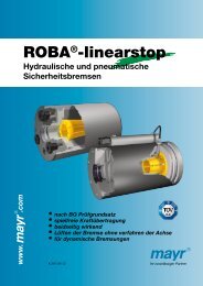
Solenoid valves for gas <strong>VAS</strong>,<br />
Double solenoid valves <strong>VCS</strong><br />
Product brochure · GB<br />
3.1.0.2 Edition 07.09<br />
• Safety shut-off of gaseous fuels, a further development of the<br />
solenoid valves for gas VG and VS<br />
• Suitable for a max. inlet pressure of 500 mbar<br />
(500 hPa/7 psig)<br />
• Easy installation into a system<br />
• Compact design saves space<br />
• No extra valve required owing to integrated<br />
flow adjustment<br />
• Check indication by blue LED<br />
• Position indicator with integral visual indicator<br />
• Suitable for high-duty cycling<br />
• Higher flow rates with the same nominal size<br />
• EC type-tested and certified<br />
• FM, CSA, UL and AGA approved<br />
(230 V AC, 120 V AC, 24 V DC)<br />
www.kromschroeder.com
2 · <strong>VAS</strong>, <strong>VCS</strong> · Edition 07.09<br />
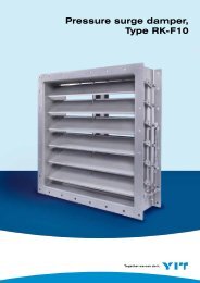
<strong>VAS</strong>..R<br />
quick opening<br />
<strong>VCS</strong>..R<br />
with damping unit<br />
Application<br />
Solenoid valves for gas <strong>VAS</strong> and double<br />
solenoid valves <strong>VCS</strong> for safeguarding and<br />
controlling the air and gas supply to gas<br />
burners and gas appliances. For use in gas<br />
control and safety systems in all sectors of<br />
the iron, steel, glass and ceramics industries,<br />
also in commercial heat generation,<br />
such as the packaging, paper and foodstuffs<br />
industries.<br />
<strong>VAS</strong>..F<br />
quick opening<br />
<strong>VCS</strong>..F with position indicator<br />
and pressure switch<br />
The modular design<br />
principle allows the<br />
individual components<br />
of the <strong>VAS</strong>, <strong>VCS</strong><br />
Series to be easily<br />
assembled: e.g. quick<br />
opening, slow opening,<br />
with position<br />
indicator and visual<br />
indicator, slow opening<br />
with attached<br />
pressure switch.<br />
Ceramics industry<br />
Aluminium industry:<br />
curing oven for<br />
wheel rims<br />
Foodstuffs industry:<br />
baking oven
<strong>VAS</strong>, <strong>VCS</strong> · Edition 07.09 · 3<br />
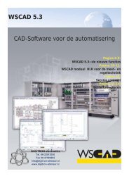
Examples of application<br />
<strong>VAS</strong> 1 – 3<br />
Damping unit with flow adjustment<br />
Plug with<br />
socket<br />
Plug<br />
Position indicator<br />
<strong>VCS</strong> 1 – 3<br />
Solenoid valve for gas <strong>VAS</strong> 1 – 3,<br />
Double solenoid valve <strong>VCS</strong> 1 – 3<br />
Threaded flange for pipe connections from<br />
DN 10 to 65, flanged connection for sizes 2<br />
and 3 for pipe connections DN 40 and 50.<br />
Modularly configurable with:<br />
– Damping unit<br />
– Position indicator<br />
– Plug (with or without socket)<br />
– Pressure test points<br />
– Pressure switch DG..C for inlet and/or<br />
outlet pressure<br />
– Tightness control TC<br />
– Bypass/pilot gas valve<br />
– Attachment block for the connection of a<br />
pressure gauge, for example.<br />
Pressure<br />
test points<br />
Pressure<br />
switch DG..C<br />
Tightness<br />
control TC<br />
Bypass/pilot gasvalve<br />
VBY for size 1<br />
Attachment block<br />
Bypass/pilot gas valve <strong>VAS</strong> for pressure gauge<br />
DG..C<br />
<strong>VAS</strong>.. N<br />
DG..C<br />
Gas solenoid valve with inlet and outlet<br />
pressure switch<br />
<strong>VAS</strong>..N, quick opening, pressure switch DG..C<br />
for inlet pressure p e and outlet pressure p a<br />
2.<br />
Double solenoid valve <strong>VCS</strong> with damping unit<br />
<strong>VCS</strong>..NL,<br />
1st valve: quick opening, quick closing, with<br />
flow adjustment,<br />
2nd valve: slow opening, quick closing.<br />
<strong>VCS</strong>..NL<br />
1.
4 · <strong>VAS</strong>, <strong>VCS</strong> · Edition 07.09<br />
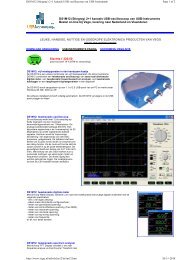
Damping unit for <strong>VAS</strong>/<strong>VCS</strong> 6–8<br />
Solenoid valve for gas <strong>VAS</strong> 6 – 9,<br />
Double solenoid valve <strong>VCS</strong> 6 – 9<br />
Gas solenoid valve and double solenoid<br />
valve with flanged connection<br />
(ISO or ANSI) for pipe connections from<br />
DN 65 to 125.<br />
<strong>VAS</strong> 6 – 9<br />
Plug with<br />
socket<br />
Position indicator<br />
Pressure test points<br />
Plug<br />
<strong>VCS</strong> 6 – 9<br />
Modularly configurable with:<br />
– Damping unit for <strong>VAS</strong>/<strong>VCS</strong> 6 – 8<br />
– Position indicator<br />
– Plug<br />
– Plug with socket<br />
<strong>VCS</strong> 6 – 9 with two threaded connections<br />
for:<br />
– Screw plugs<br />
– Pressure test points<br />
– Pressure switch DG..C for inlet/interspace<br />
pressure<br />
– Tightness control TC<br />
Screw<br />
plugs<br />
Pressure<br />
switch DG..C<br />
Tightness -<br />
control TC<br />
<strong>VAS</strong> 6 – 9 <strong>VCS</strong> 6 – 9<br />
Plug with<br />
socket<br />
Plug<br />
Pressure test<br />
points<br />
Measuring<br />
adapter<br />
Position indicator<br />
Damping unit for<br />
<strong>VAS</strong>/<strong>VCS</strong> 6–8<br />
Screw<br />
plugs<br />
Pressure<br />
switch DG..C<br />
Bypass<br />
adapter<br />
Tightness control TC<br />
Relief line adapter<br />
11⁄2 NPT, Rp 1<br />
Solenoid valve for gas <strong>VAS</strong> 6 – 9,<br />
Double solenoid valve <strong>VCS</strong> 6 – 9 with<br />
connection for adapter plates<br />
Gas solenoid valve and double solenoid<br />
valve with flanged connection (ISO or ANSI)<br />
for pipe connections from DN 65 to 125.<br />
Modularly configurable with:<br />
– Damping unit for <strong>VAS</strong>/<strong>VCS</strong> 6–8<br />
– Position indicator<br />
– Plug<br />
– Plug with socket<br />
With adapter plates, expandable with:<br />
– Pressure switch DG..C<br />
<strong>VAS</strong> 6 – 9: for inlet/outlet pressure<br />
<strong>VCS</strong> 6 – 9: for interspace/outlet pressure<br />
– Pressure test points<br />
– Screw plug<br />
– Bypass or pilot gas valve <strong>VAS</strong><br />
<strong>VCS</strong> 6 – 9<br />
With two threaded connections for:<br />
– Screw plugs<br />
– Pressure test points<br />
– Pressure switch DG..C for inlet/interspace<br />
pressure<br />
– Tightness control TC<br />
Expandable with relief line adapter (1½ NPT,<br />
Rp 1) for relief line.<br />
Pressure<br />
switch DG..C<br />
Bypass/<br />
pilot gas valve <strong>VAS</strong>
<strong>VAS</strong>, <strong>VCS</strong> · Edition 07.09 · 5<br />
<strong>VAS</strong>..F..N<br />
Gas solenoid valve with pilot gas valve<br />
and pressure switch<br />
<strong>VAS</strong>..F..N: quick opening, quick closing,<br />
<strong>VAS</strong> 1 as pilot gas valve with pressure<br />
switch DG..C.<br />
<strong>VAS</strong> 1<br />
DG..C<br />
<strong>VCS</strong>..F..N<br />
Double solenoid valve with tightness<br />
control<br />
<strong>VCS</strong>..F..N: quick opening, quick closing<br />
valves, tightness control TC 116V.<br />
TC 116V
6 · <strong>VAS</strong>, <strong>VCS</strong> · Edition 07.09<br />
Replacement possibilities<br />
Solenoid valve for gas VG is to be replaced by <strong>VAS</strong><br />
Type<br />
VG Solenoid valve for gas Solenoid valve for gas <strong>VAS</strong><br />
10/15 DN 10 internal 15 mm (0.59") Size 1 DN 10 110<br />
15 DN 15 Size 1 DN 15 115<br />
15/12 DN 15 internal 12 mm (0.47") – – –<br />
20 DN 20 Size 1 DN 20 120<br />
25 DN 25 Size 1 DN 25 125<br />
25/15 DN 25 internal 15 mm (0.59") – – –<br />
40/32 DN 40 internal 32 mm (1.26") Size 2 DN 40 240<br />
40 DN 40 Size 2 DN 40 240<br />
40/33 DN 40 internal 33 mm (1.30") – – –<br />
50 DN 50 Size 3 DN 50 350<br />
50/39 DN 50 internal 39 mm (1.54") – – –<br />
50/65 DN 50 internal 65 mm (2.59") Size 3 DN 50 350<br />
65 DN 65 Size 3 DN 65 365<br />
65 Size 6 DN 65 665<br />
65/49 DN 65 internal 49 mm (1.93") – – –<br />
80 DN 80 Size 7 DN 80 780<br />
100 DN 100 Size 8 DN 100 8100<br />
T T-product T-product T<br />
R Rp internal thread Rp internal thread R<br />
N NPT internal thread NPT internal thread N<br />
F ISO fl ange ISO fl ange F<br />
A ANSI fl ange ANSI fl ange A<br />
02 p e max.: 200 mbar (200 hPa/2 psig) p e max.: 500 mbar (500 hPa/7 psig) <br />
03 360 mbar (360 hPa/5 psig) 500 mbar (500 hPa/7 psig) <br />
10 1000 mbar (1000 hPa/14.5 psig) – –<br />
18 1800 mbar (1800 hPa/26.1 psig) – –<br />
N Quick opening Quick opening /N<br />
L Slow opening Slow opening /L<br />
K Mains voltage: 24 V DC Mains voltage: 24 V DC K<br />
– – 100 V AC P<br />
Q 120 V AC 120 V AC Q<br />
– – 200 V AC Y<br />
Type T 220/240 V AC 230 V AC Type W<br />
3 Electrical connection via terminals Electrical connection via terminals 3<br />
6 Electrical connection via socket Electrical connection via socket <br />
9 Metal terminal connection box Electrical connection via terminals 3<br />
1 Screw plug at the inlet Screw plug at the inlet and outlet <br />
3 Screw plug at the inlet and outlet Screw plug at the inlet and outlet <br />
4 Pressure test point at the inlet Pressure test point at the inlet and outlet* <br />
6 Pressure test point at the inlet and outlet Pressure test point at the inlet and outlet* <br />
D Flow adjustment Flow adjustment*** <br />
S Position indicator Position indicator with visual indicator** S<br />
G Position indicator for 24 V Position indicator for 24 V with visual indicator** G<br />
OCS Valve stem overtravel switch Position indicator with visual indicator** S<br />
CPS Position indicator Position indicator with visual indicator** S<br />
VI Visual indicator Position indicator with visual indicator** S<br />
M Suitable for biologically produced methane Suitable for biologically produced methane <br />
V Viton valve disc seal Viton valve disc seal –<br />
Example<br />
VG 25R02NT31DM<br />
Type<br />
Example<br />
<strong>VAS</strong> 125R/NW<br />
= standard, available<br />
For length compensation when replacing VG by <strong>VAS</strong> 6 – 9 install an adapter for length compensation – see Accessories, Adapter for length compensation.<br />
* Pressure test points may be attached at the left and/or right-hand side.<br />
** Position indicator with visual indicator can be attached at the left- or right-hand side.<br />
*** Flow adjustment for <strong>VAS</strong>/VCL..N 1 -3, <strong>VAS</strong>/VCL 1 – 2..L.
<strong>VAS</strong>, <strong>VCS</strong> · Edition 07.09 · 7<br />
MODULINE solenoid valves for gas VS is to be replaced by <strong>VAS</strong><br />
Type Flange Type<br />
VS Solenoid valve for gas Solenoid valve for gas <strong>VAS</strong><br />
115 3<br />
/8"<br />
Size 115<br />
125<br />
Size 125<br />
Size 1, DN 10 110<br />
115<br />
125<br />
½"<br />
Size 115<br />
Size 125<br />
Size 1, DN 15 115<br />
115<br />
125<br />
¾"<br />
Size 115<br />
Size 125<br />
Size 1, DN 20 120<br />
115<br />
125<br />
1"<br />
Size 115<br />
Size 125<br />
Size 1, DN 25 125<br />
230<br />
240<br />
1"<br />
Size 232<br />
Size 240<br />
Size 2, DN 25 225<br />
232<br />
240<br />
1½"<br />
Size 232<br />
Size 240<br />
Size 2, DN 40 240<br />
350 1½" Size 350 Size 3, DN 40 340<br />
350 2" Size 350 Size 3, DN 50 350<br />
ML<br />
MODULINE + connection fl anges<br />
Rp internal thread<br />
Rp internal thread<br />
R<br />
TML<br />
MODULINE + connection fl anges NPT<br />
internal thread<br />
NPT internal thread<br />
N<br />
02 p e max. 200 mbar (200 hPa/2 psig) p e max. 500 mbar (500 hPa/7 psig) <br />
03 p e max. 360 mbar (360 hPa/3 psig) p e max. 500 mbar (500 hPa/7 psig) <br />
N Quick opening Quick opening /N<br />
L Slow opening Slow opening /L<br />
D Flow adjustment Flow adjustment* <br />
K Mains voltage: 24 V DC Mains voltage: 24 V DC K<br />
– – 100 V AC P<br />
Q 120 V AC 120 V AC Q<br />
– – 200 V AC Y<br />
Type T Flange 220/240 V AC 230 V AC Type W<br />
3 Electrical connection via terminals Electrical connection via terminals 3<br />
6 Electrical connection via socket Electrical connection via socket <br />
9 Metal terminal connection box Electrical connection via terminals 3<br />
Pressure test point at the inlet Pressure test point at the inlet and outlet <br />
S Position indicator Position indicator S<br />
G Position indicator for 24 V Position indicator for 24 V G<br />
M non-ferrous metals non-ferrous metals <br />
V Viton valve disc seal – –<br />
Example<br />
VS 240ML02LT3<br />
with Rp 1½ connection fl anges<br />
* Flow adjustment for <strong>VAS</strong>/VCL..N 1 -3, <strong>VAS</strong>/VCL 1 – 2..L.<br />
= standard, available<br />
Example<br />
<strong>VAS</strong> 240R/LW<br />
with test points
8 · <strong>VAS</strong>, <strong>VCS</strong> · Edition 07.09<br />
Selection<br />
Selection table <strong>VAS</strong> 1 – 3<br />
Accessories right<br />
Accessories left<br />
M20-cable gland<br />
Plug with socket<br />
Plug without socket<br />
Screw plug<br />
Pressure test point<br />
DG 17VC 2)<br />
DG 40VC 2)<br />
DG 110VC 2)<br />
DG 300VC 2)<br />
Bypass valve VBY<br />
Bypass valve <strong>VAS</strong> 1<br />
Screw plug<br />
Pressure test point<br />
DG 17VC 2)<br />
DG 40VC 2)<br />
DG 110VC 2)<br />
DG 300VC 2)<br />
Bypass valve VBY<br />
Bypass valve <strong>VAS</strong> 1<br />
Type T R N F /N /L K P Q Y W S 1) G 1) R 1) L 1)<br />
<strong>VAS</strong> 1 – – – <br />
<strong>VAS</strong> 1-0 – – – <br />
<strong>VAS</strong> 110 – <br />
<strong>VAS</strong> 115 – <br />
<strong>VAS</strong> 120 – <br />
<strong>VAS</strong> 125 – <br />
<strong>VAS</strong> 2 – – – – – <br />
<strong>VAS</strong> 225 – – – <br />
<strong>VAS</strong> 232 – – – <br />
<strong>VAS</strong> 240 – – <br />
<strong>VAS</strong> 250 – – – <br />
<strong>VAS</strong> 3 – – – – – <br />
<strong>VAS</strong> 340 – – – <br />
<strong>VAS</strong> 350 – – <br />
<strong>VAS</strong> 365 – – – <br />
= standard, = available<br />
1) Position indicator and bypass /pilot gas valve cannot be fi tted together on the same side.<br />
2) Specify the test point for inlet pressure p e or outlet pressure p a .<br />
Help for dimensioning and confi guring the gas solenoid valve <strong>VAS</strong> can be found in the program “Product Selection”<br />
on the Catalogue DVD. You can order the Catalogue DVD at<br />
www.kromschroeder.com <strong>Products</strong> CD-ROMs Catalogue.<br />
Order example<br />
<strong>VAS</strong> 225R/NW<br />
Fitted pressure<br />
switch for test<br />
point p e<br />
Type code <strong>VAS</strong> 1– 3<br />
Code<br />
Description<br />
<strong>VAS</strong><br />
Gas solenoid valve<br />
1 – 3 Size<br />
T<br />
T product<br />
–<br />
no inlet- and no outlet fl ange<br />
-0<br />
blind fl ange<br />
10 – 65<br />
Nominal inlet and outlet diameter<br />
R<br />
N<br />
F<br />
/N<br />
/L<br />
K<br />
P<br />
Q<br />
Y<br />
W<br />
S<br />
G<br />
R<br />
L<br />
Rp internal thread<br />
NPT internal thread<br />
ISO fl ange<br />
quick opening, quick closing<br />
slow opening, quick closing<br />
Mains voltage 24 V DC<br />
Mains voltage 100 V AC; 50/60 Hz<br />
Mains voltage 120 V AC; 50/60 Hz<br />
Mains voltage 200 V AC; 50/60 Hz<br />
Mains voltage 230 V AC; 50/60 Hz<br />
Position indicator with visual indicator<br />
Position indicator for 24 V with visual indicator<br />
Viewed from the right (in the direction of fl ow)<br />
Viewed from the left (in the direction of fl ow)
<strong>VAS</strong>, <strong>VCS</strong> · Edition 07.09 · 9<br />
Selection table <strong>VAS</strong> 6 – 9<br />
Plug with socket<br />
Plug without socket<br />
Accessories right<br />
Accessories left<br />
Inlet Outlet Inlet Outlet<br />
Type T F A 05 /N /L K Q W A S G R L 3 P M /P/M /1 /2/3/4/B/Z/V/E P M 1 2 3 4 - /P/M /1 /2/3/4/B/Z/V/E P M 1 2 3 4 -<br />
<strong>VAS</strong> 665 – <br />
<strong>VAS</strong> 780 – <br />
<strong>VAS</strong> 8100 – <br />
<strong>VAS</strong> 9125 – – – – <br />
= standard, = available<br />
Help for dimensioning and confi guring the gas solenoid valve <strong>VAS</strong> can be found in the program<br />
“Product Selection” on the Catalogue DVD. You can order the Catalogue DVD at<br />
www.kromschroeder.com <strong>Products</strong> CD-ROMs Catalogue.<br />
Order example<br />
<strong>VAS</strong> 665F05/NW3P/P2/PP<br />
Type code <strong>VAS</strong> 6– 9<br />
Code<br />
Description<br />
<strong>VAS</strong><br />
Gas solenoid valve<br />
6 – 9 Size<br />
T<br />
T product<br />
65 – 125 Nominal inlet diameter<br />
F<br />
ISO fl ange<br />
A<br />
ANSI fl ange<br />
05 Max. inlet pressure p e max. 500 mbar (500 hPa/7 psig)<br />
/N<br />
quick opening, quick closing<br />
/L<br />
slow opening, quick closing<br />
K<br />
Mains voltage 24 V DC<br />
Q<br />
Mains voltage 120 V AC; 50/60 Hz<br />
W<br />
Mains voltage 230 V AC; 50/60 Hz<br />
A<br />
Mains voltage 120 – 230 V AC; 50/60 Hz<br />
S<br />
Position indicator with visual indicator<br />
G<br />
Position indicator for 24 V with visual indicator<br />
R<br />
Viewed from the right (in the direction of fl ow)<br />
L<br />
Viewed from the left (in the direction of fl ow)<br />
3 Electrical connection: M20 cable gland<br />
P<br />
2 screw plugs at the inlet and outlet<br />
M<br />
2 pressure test points at the inlet ans outlet<br />
Accessories, right, inlet<br />
/P<br />
Screw plug<br />
/M<br />
Pressure test point for inlet pressure p e<br />
/1<br />
Gas pressure switch DG 17VC<br />
/2<br />
Gas pressure switch DG 40VC<br />
/3<br />
Gas pressure switch DG 110VC<br />
/4<br />
Gas pressure switch DG 300VC<br />
/B<br />
Bypass valve <strong>VAS</strong> 1, fi tted<br />
/Z<br />
Pilot gas valve <strong>VAS</strong> 1, fi tted<br />
/V<br />
Prepared for breather line 1½ NPT<br />
/E<br />
Prepared for breather line Rp 1<br />
P<br />
M<br />
1<br />
2<br />
3<br />
4<br />
-<br />
Accessories, left, outlet<br />
Screw plug<br />
Pressure test point for inlet pressure p a<br />
Gas pressure switch DG 17VC<br />
Gas pressure switch DG 40VC<br />
Gas pressure switch DG 110VC<br />
Gas pressure switch DG 300VC<br />
none accessories<br />
Code<br />
/P<br />
/M<br />
/1<br />
/2<br />
/3<br />
/4<br />
/B<br />
/Z<br />
/V<br />
/E<br />
P<br />
M<br />
1<br />
2<br />
3<br />
4<br />
-<br />
Description<br />
Accessories, right, inlet<br />
Screw plug<br />
Pressure test point for inlet pressure p e<br />
Gas pressure switch DG 17VC<br />
Gas pressure switch DG 40VC<br />
Gas pressure switch DG 110VC<br />
Gas pressure switch DG 300VC<br />
Bypass valve <strong>VAS</strong> 1, fi tted<br />
Pilot gas valve <strong>VAS</strong> 1, fi tted<br />
Prepared for breather line 1½ NPT<br />
Prepared for breather line Rp 1<br />
Accessories, left, outlet<br />
Screw plug<br />
Pressure test point for inlet pressure p a<br />
Gas pressure switch DG 17VC<br />
Gas pressure switch DG 40VC<br />
Gas pressure switch DG 110VC<br />
Gas pressure switch DG 300VC<br />
none accessories
10 · <strong>VAS</strong>, <strong>VCS</strong> · Edition 07.09<br />
Selection table <strong>VCS</strong> 1 – 3<br />
Accessories right 1. valve 2) Accessories left 2. valve 2)<br />
M20-cable gland<br />
Plug with socket<br />
Plug without socket<br />
Screw plug<br />
Pressure test point<br />
DG 17VC 3)<br />
DG 40VC 3)<br />
DG 110VC 3)<br />
DG 300VC 2)<br />
Bypass valve VBY<br />
Bypass valve <strong>VAS</strong> 1<br />
Screw plug<br />
Pressure test point<br />
DG 17VC 3)<br />
DG 40VC 3)<br />
DG 110VC 3)<br />
DG 300VC 3)<br />
Bypass valve VBY<br />
Bypass valve <strong>VAS</strong> 1<br />
Type T R N F N L N L K P Q Y W S 1) G 1) R 1) L 1)<br />
<strong>VCS</strong> 1 – – – <br />
<strong>VCS</strong> 1-0 – – – <br />
<strong>VCS</strong> 110 – <br />
<strong>VCS</strong> 115 – <br />
<strong>VCS</strong> 120 – <br />
<strong>VCS</strong> 125 – <br />
<strong>VCS</strong> 2 – – – – – <br />
<strong>VCS</strong> 225 – – – <br />
<strong>VCS</strong> 232 – – – <br />
<strong>VCS</strong> 240 – – <br />
<strong>VCS</strong> 250 – – – <br />
<strong>VCS</strong> 3 – – – – – <br />
<strong>VCS</strong> 340 – – – <br />
<strong>VCS</strong> 350 – – <br />
<strong>VCS</strong> 365 – – – <br />
= standard, = available<br />
1) Position indicator and bypass/pilot gas valve cannot be fi tted together on the same side.<br />
2) The same accessories can be selected for the left- or right-hand side.<br />
3) Specify the test point for inlet pressure p e , interspace pressure p z or outlet pressure p a . When attaching<br />
DG..VC for p z , the installation space left at the other valve is only suffi cient for screw plugs.<br />
Order example<br />
<strong>VAS</strong> 225RNNW<br />
Fitted pressure<br />
switch for test<br />
point p e<br />
Type code <strong>VCS</strong> 1– 3<br />
Code<br />
Description<br />
<strong>VCS</strong><br />
Gas solenoid valve<br />
1 – 3 Size<br />
T<br />
T product<br />
–<br />
-0<br />
10 – 65<br />
no inlet- and no outlet fl ange<br />
blind fl ange<br />
Nominal inlet and outlet diameter<br />
R<br />
N<br />
F<br />
N<br />
L<br />
N<br />
L<br />
K<br />
P<br />
Q<br />
Y<br />
W<br />
S<br />
G<br />
R<br />
L<br />
Rp internal thread<br />
NPT internal thread<br />
ISO fl ange<br />
1. valve quick opening, quick closing<br />
1. valve slow opening, quick closing<br />
2. valve quick opening, quick closing<br />
2. valve slow opening, quick closing<br />
Mains voltage 24 V DC<br />
Mains voltage 100 V AC; 50/60 Hz<br />
Mains voltage 120 V AC; 50/60 Hz<br />
Mains voltage 200 V AC; 50/60 Hz<br />
Mains voltage 230 V AC; 50/60 Hz<br />
Position indicator with visual indicator<br />
Position indicator for 24 V with visual indicator<br />
Viewed from the right (in the direction of fl ow)<br />
Viewed from the left (in the direction of fl ow)
<strong>VAS</strong>, <strong>VCS</strong> · Edition 07.09 · 11<br />
Selction table <strong>VCS</strong> 6 – 9<br />
Plug with socked<br />
Plug without socked<br />
Accessories right 1)<br />
Inlet Interspace 1 Interspace 2 Outlet<br />
Type T F A 05 N L N L K Q W A S G R L 3 P M /P /M /1 /2 /3 /4 P M 1 2 3 4 P M 1 2 3 4 B Z V E - P M 1 2 3 4 -<br />
<strong>VCS</strong> 665 – <br />
<strong>VCS</strong> 780 – <br />
<strong>VCS</strong> 8100 – <br />
<strong>VCS</strong> 9125 – – – – <br />
= standard, = available<br />
1) The “accessories on the left-hand side”, have the same type code<br />
as the “accessories on the right hand side”.<br />
Order example<br />
<strong>VAS</strong> 665F05NLW3P/2B-/PPPP<br />
Type code <strong>VCS</strong> 6– 9<br />
Code<br />
Description<br />
<strong>VCS</strong> Gas solenoid valve<br />
6 – 9 Size<br />
T<br />
T product<br />
65 – 125 Nominal inlet diameter<br />
F<br />
ISO fl ange<br />
A<br />
ANSI fl ange<br />
05 Max. inlet pressure p e max. 500 mbar (500 hPa/7 psig)<br />
N<br />
1. valve quick opening, quick closing<br />
L<br />
1. valve slow opening, quick closing<br />
N<br />
2. valve quick opening, quick closing<br />
L<br />
2. valve slow opening, quick closing<br />
K<br />
Mains voltage 24 V DC<br />
Q<br />
Mains voltage 120 V~; 50/60 Hz<br />
W<br />
Mains voltage 230 V~; 50/60 Hz<br />
A<br />
Mains voltage 120 – 230 V~; 50/60 Hz<br />
S<br />
Position indicator with visual indicator<br />
G<br />
Position indicator for 24 V with visual indicator<br />
R<br />
Viewed from the right (in the direction of fl ow)<br />
L<br />
Viewed from the left (in the direction of fl ow)<br />
3 Electrical connection: M20 cable gland<br />
P<br />
2 screw plugs at the inlet and outlet<br />
M<br />
2 pressure test points at the inlet ans outlet<br />
Code<br />
/P<br />
/M<br />
/1<br />
/2<br />
/3<br />
/4<br />
P<br />
M<br />
1<br />
2<br />
3<br />
4<br />
P<br />
M<br />
1<br />
2<br />
3<br />
4<br />
B<br />
Z<br />
V<br />
E<br />
-<br />
P<br />
M<br />
1<br />
2<br />
3<br />
4<br />
-<br />
Description<br />
Accessories, right, inlet<br />
Screw plug<br />
Pressure test point for inlet pressure p e<br />
Gas pressure switch DG 17VC<br />
Gas pressure switch DG 40VC<br />
Gas pressure switch DG 110VC<br />
Gas pressure switch DG 300VC<br />
Accessories, left, interspace 1<br />
Screw plug<br />
Test point for interspace pressure p z<br />
Gas pressure switch DG 17VC<br />
Gas pressure switch DG 40VC<br />
Gas pressure switch DG 110VC<br />
Gas pressure switch DG 300VC<br />
Accessories, right, interspace 2<br />
Screw plug<br />
Test point for interspace pressure p z<br />
Gas pressure switch DG 17VC<br />
Gas pressure switch DG 40VC<br />
Gas pressure switch DG 110VC<br />
Gas pressure switch DG 300VC<br />
Bypass valve <strong>VAS</strong> 1, fi tted<br />
Pilot gas valve <strong>VAS</strong> 1, fi tted<br />
Prepared for breather line 1½ NPT<br />
Prepared for breather line Rp 1<br />
none accessories<br />
Accessories, left, outlet<br />
Screw plug<br />
Pressure test point for inlet pressure p a<br />
Gas pressure switch DG 17VC<br />
Gas pressure switch DG 40VC<br />
Gas pressure switch DG 110VC<br />
Gas pressure switch DG 300VC<br />
none accessories<br />
1) The “accessories on the left-hand side”, have the same type code<br />
as the “accessories on the right hand side”.
<strong>VAS</strong>, <strong>VCS</strong> · Edition 07.09 · 12<br />
Technical data<br />
Types of gas: Natural gas, LPG (gaseous), biologically produced<br />
methane (max. 0.1 %-by-vol. H 2 S) or air; other gases on request.<br />
The gas must be dry in all temperature conditions and must not<br />
condense.<br />
Max. inlet pressure p e : 500 mbar (500 hPa/7 psig).<br />
FM approved (230 V AC, 120 V AC, 24 V DC), non operational pressure:<br />
700 mbar (700 hPa/10 psig).<br />
CSA approved (230 V AC, 120 V AC, 24 V DC): 350 mbar<br />
(350 hPa/5 psig).<br />
Flow adjustment limits the maximum flow volume between 20 and<br />
100%. On <strong>VAS</strong> 1 – 3, the setting can be monitored on an indicator.<br />
Adjustment of the start gas rate: 0 to 70%.<br />
Opening times:<br />
<strong>VAS</strong>../N quick opening: ≤ 1 s;<br />
<strong>VAS</strong>../L slow opening: up to 30 s.<br />
Closing time:<br />
<strong>VAS</strong>../N, <strong>VAS</strong>../L quick closing: < 1 s.<br />
Ambient temperature: -20 to +60°C (-4 to +140°F),<br />
no condensation permitted.<br />
Storage temperature: -20 to +40 °C (-4 to +104 °F),<br />
no condensation permitted.<br />
Safety valve:<br />
Class A Group 2 pursuant to EN 13611 and EN 161,<br />
Factory Mutual (FM) Research Class (230 V AC, 120 V AC, 24 V DC):<br />
7410 and 7411, ANSI Z21.21 and CSA 6.5,<br />
ANSI Z21.21 and CSA 6.5.<br />
Mains voltage:<br />
230 V AC, +10/-15%, 50/60 Hz;<br />
200 V AC, +10/-15%, 50/60 Hz;<br />
120 V AC, +10/-15%, 50/60 Hz;<br />
100 V AC, +10/-15%, 50/60 Hz;<br />
24 V DC, ±20 %;<br />
<strong>VAS</strong>/<strong>VCS</strong> 9: 120 – 230 V~, +10/-15 %, 50/60 Hz.<br />
Cable gland: M20 x 1.5<br />
Electrical connection: max. 2.5 mm 2 (AWG 12) or plug with socket<br />
to EN 175301-803.<br />
Power consumption:<br />
Type<br />
24 V DC<br />
[W]<br />
100 V AC<br />
[W]<br />
120 V AC<br />
[W]<br />
200 V AC<br />
[W]<br />
230 V AC<br />
[W]<br />
<strong>VAS</strong> 1 29 33 30 33 30<br />
<strong>VAS</strong> 2 46 53 54 54 53<br />
<strong>VAS</strong> 3 46 53 54 54 53<br />
<strong>VAS</strong> 6 70 – 63 – 63<br />
<strong>VAS</strong> 7 75 – 90 – 83<br />
<strong>VAS</strong> 8 99 – 117 – 113<br />
<strong>VAS</strong> 9 – – 200 (15*) – 200 (15*)<br />
<strong>VCS</strong> 1 58 66 60 66 60<br />
<strong>VCS</strong> 2 92 106 108 108 106<br />
<strong>VCS</strong> 3 92 106 108 108 106<br />
<strong>VCS</strong> 6 140 – 126 – 126<br />
<strong>VCS</strong> 7 150 – 180 – 166<br />
<strong>VCS</strong> 8 198 – 234 – 226<br />
<strong>VCS</strong> 9 – – 400 (30*) – 400 (30*)<br />
Enclosure: IP 65.<br />
Duty cycle: 100%.<br />
Power factor of the solenoid coil: cos ϕ = 1.<br />
Switching frequency:<br />
<strong>VAS</strong>..N: Arbitrary,<br />
<strong>VAS</strong>..L: There must be a period of 20 seconds between switching<br />
off and on again so that the damping is fully effective.<br />
Valve housing: Aluminium,<br />
Valve seal: NBR.<br />
Connection flanges:<br />
<strong>VAS</strong>/<strong>VCS</strong> 1-3 with internal thread:<br />
Rp pursuant to ISO 7-1, NPT pursuant to ANSI/ASME<br />
<strong>VAS</strong>/<strong>VCS</strong> 6-9 with ISO flange pursuant to ISO 7005, with ANSI<br />
flange pursuant to ASA.<br />
Position indicator contact rating:<br />
Type<br />
<strong>VAS</strong>..S,<br />
<strong>VCS</strong>..S<br />
<strong>VAS</strong>..G,<br />
<strong>VCS</strong>..G<br />
Voltage<br />
12 – 250 V AC,<br />
50/60 Hz<br />
12 – 125 V AC,<br />
50/60 Hz<br />
Min. current<br />
(resistive load)<br />
Max. current<br />
(resistive load)<br />
100 mA 3 A<br />
2 mA 0.1 A<br />
Position indicator switching frequency: max. 5× per minute.<br />
Switching<br />
Switching cycles*<br />
current [A]<br />
cos ϕ = 1 cos ϕ = 0.6<br />
0.1 500,000 500,000<br />
0.5 300,000 250,000<br />
1 200,000 100,000<br />
3 100,000 –<br />
* Limited to max. 200,000 cycles for heating systems.<br />
<strong>VAS</strong>/<strong>VCS</strong> 9<br />
Switching frequency: max. 1× per minute.<br />
Max. temperature of solenoid coil:<br />
+20°C (+68°F) above ambient temperature.<br />
Current consumption at 20°C (68°F):<br />
Pick-up current: 1.8 A<br />
Holding current: 0.3 A.<br />
* After opening.
13 · <strong>VAS</strong>, <strong>VCS</strong> · Edition 07.09<br />
Certification<br />
EC type-tested and certified<br />
pursuant to<br />
– Gas Appliances Directive (90/396/EEC) in conjunction with EN<br />
13611 and EN 161.<br />
Meets the requirements of the<br />
– Low Voltage Directive (2006/95/EC),<br />
– EMC Directive (2004/108/EC).<br />
FM approved (230 V AC, 120 V AC, 24 V DC)<br />
Factory Mutual Research Class: 7410 and 7411 Safety overpressure<br />
slam shut valves.<br />
Designed for applications pursuant to NFPA 85 and NFPA 86.<br />
www.fmglobal.com → <strong>Products</strong> and Services → Product Certification<br />
→ Approval Guide<br />
CSA approved (230 V AC, 120 V AC, 24 V DC)<br />
Canadian Standards Association – ANSI Z21.21 and CSA 6.5<br />
www.directories.csa-international.org<br />
Class number: 3371-83 (natural gas, LPG), 3371-03 (natural gas,<br />
propane)<br />
UL approved (230 V AC, 120 V AC, 24 V DC)<br />
Underwriters Laboratories – UL 429 “Electrically operated valves”.<br />
http://database.ul.com<br />
AGA approved (230 V AC, 120 V AC, 24 V DC)<br />
Australian Gas Association<br />
Scan of the AGA approval (GB)<br />
– see www.docuthek.com Elster Kromschröder <br />
<strong>Products</strong> 03 Valves and butterfly valves Solenoid valves for<br />
gas <strong>VAS</strong> Kind of document: Certificate <br />
<strong>VAS</strong> (AGA Standard) / <strong>VCS</strong> (AGA Standard)
14 · <strong>VAS</strong>, <strong>VCS</strong> · Edition 07.09<br />
Detailed information on this<br />
product<br />
www.docuthek.com<br />
Contact<br />
www.kromschroeder.com Sales<br />
Elster GmbH<br />
Postfach 2809 · 49018 Osnabrück<br />
Strotheweg 1 · 49504 Lotte (Büren)<br />
Germany<br />
T +49 541 1214-0<br />
F +49 541 1214-370<br />
info@kromschroeder.com<br />
www.kromschroeder.com<br />
www.elster.com<br />
Kromschröder, a product<br />
brand of the Elster Group<br />
We reserve the right to make technical modifications<br />
in the interests of progress.<br />
Copyright © 2007 Elster Group<br />
All rights reserved.<br />
03250359 MM.JJ 0.000