CENTAX®-SEC - Industrial and Bearing Supplies
CENTAX®-SEC - Industrial and Bearing Supplies
CENTAX®-SEC - Industrial and Bearing Supplies

Erfolgreiche ePaper selbst erstellen
Machen Sie aus Ihren PDF Publikationen ein blätterbares Flipbook mit unserer einzigartigen Google optimierten e-Paper Software.
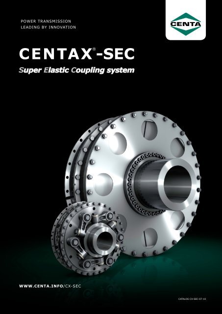
POWER TRANSMISSION<br />
LEADING BY INNOVATION<br />
CENTAX® -<strong>SEC</strong><br />
Super Elastic Coupling system<br />
WWW.CENTA.INFO/CX-<strong>SEC</strong><br />
CATALOG CX-<strong>SEC</strong>-07-10
Contents<br />
Inhaltsverzeichnis<br />
Introduction, Torsional Responsibility<br />
Intro-1<br />
Vorwort, Drehschwingungsverantwortung<br />
Intro-1<br />
Company Profile<br />
Intro-2<br />
Firmenprofil<br />
Intro-2<br />
CENTAX - <strong>SEC</strong> - System<br />
Intro-5<br />
CENTAX - <strong>SEC</strong> - System<br />
Intro-5<br />
Description of the components<br />
Intro-16<br />
Beschreibung der Komponenten<br />
Intro-16<br />
Classification, QA<br />
Intro-23<br />
Klassifikation, QS<br />
Intro-23<br />
Series 00 00-1<br />
Technical Data 00-2<br />
Dimensions Series G 00-4<br />
Dimensions Series L 00-7<br />
Series 100 100-1<br />
Technical Data 100-2<br />
Dimensions Series G 100-4<br />
Dimensions Series L 100-10<br />
Series 200 200-1<br />
Technical Data 200-2<br />
Dimensions Series G 200-4<br />
Dimensions Series L 200-8<br />
Series 400 400-1<br />
Technical Data 400-2<br />
Dimensions Series G 400-3<br />
CENTAX-B B-1<br />
Technical Data B-4<br />
Dimensions, Ring elements B-5<br />
Dimensions, Segmented Elements B-6<br />
Series 300 300-1<br />
Technical Data 300-3<br />
Dimensions 300-4<br />
Baureihe 00 00-1<br />
Technische Daten 00-2<br />
Abmessungen Bauform G 00-4<br />
Abmessungen Bauform L 00-7<br />
Baureihe 100 100-1<br />
Technische Daten 100-2<br />
Abmessungen Bauform G 100-4<br />
Abmessungen Bauform L 100-10<br />
Baureihe 200 200-1<br />
Technische Daten 200-2<br />
Abmessungen Bauform G 200-4<br />
Abmessungen Bauform L 200-8<br />
Baureihe 400 400-1<br />
Technische Daten 400-2<br />
Abmessungen Bauform G 400-3<br />
CENTAX-B B-1<br />
Technische Daten B-4<br />
Abmessungen Ringelemente B-5<br />
Abmessungen, Segmentierte Elemente B-6<br />
Baureihe 300 300-1<br />
Technische Daten 300-3<br />
Abmessungen 300-4<br />
CENTAX-N/NL<br />
Technical Data<br />
Dimensions<br />
N/NL-1<br />
N/NL-3<br />
N/NL-4<br />
CENTAX-N/NL<br />
Technische Daten<br />
Abmessungen<br />
N/NL-1<br />
N/NL-3<br />
N/NL-4<br />
CENTAX-TT<br />
Technical Data<br />
Dimensions<br />
TT-1<br />
TT-6<br />
TT-7<br />
CENTAX-TT<br />
Technische Daten<br />
Abmessungen<br />
TT-1<br />
TT-6<br />
TT-7<br />
Explanation of the technical data<br />
app-1<br />
Erläuterung der technischen Daten<br />
app-1<br />
Storage of CENTAX Elements<br />
app-9<br />
Lagerung der Gummielemente<br />
app-9<br />
Protection of the Rubber Surface<br />
app-9<br />
Oberflächenschutz der Gummielemente<br />
app-9<br />
CX-<strong>SEC</strong>-2<br />
CATALOG CX-<strong>SEC</strong>-07-10
Introduction<br />
This catalog supersedes previous editions. CENTA reserves<br />
the right to amend any dimension or detail specified or illustrated<br />
in this publication without notice <strong>and</strong> without incurring<br />
any obligation to provide such modification to couplings<br />
previously delivered. This catalog shows the extent<br />
of our CENTAX ® -<strong>SEC</strong> coupling range at the time of printing.<br />
This program is still being extended with further sizes<br />
<strong>and</strong> series. Any changes due to technological progress are<br />
reserved, for questions please contact CENTA.<br />
If you are unable to find a suitable coupling for your application<br />
please do not hesitate to contact us. The experience<br />
of CENTA gained since 1970 of coupling manufacturing<br />
with millions couplings sold, combined with our extensive<br />
range <strong>and</strong> broad variety of coupling series, allow<br />
us to provide a good technical <strong>and</strong> economic solution for<br />
almost all problems.<br />
All technical data in this catalog are according to the metric<br />
SI system. All dimensions are in mm. All hub dimensions<br />
(N, N 1<br />
<strong>and</strong> N 2<br />
) may vary, depending on the required<br />
finished bore. Alle dimensions for masses (m), inertias<br />
(S) <strong>and</strong> centres of gravity (S) refer to the maximum bore<br />
diameter.<br />
We would like to draw your attention to the need of preventing<br />
accidents or injury. No safety guards are included<br />
in our supply.<br />
Copyright to this technical document is held acc. ISO<br />
16016. CENTAX ® is a registered trademark of CENTA Antriebe.<br />
Torsional responsibility<br />
The responsibility for ensuring the torsional vibration compatibility<br />
of the complete drive train, rests with the final<br />
assembler. As a component supplier CENTA is not responsible<br />
for such calculations, <strong>and</strong> cannot accept any liability<br />
for gear noise/ -damage or coupling damage caused by<br />
torsional vibrations.<br />
CENTA recommends that a torsional vibration analysis<br />
(TVA) is carried out on the complete drive train prior to<br />
start up of the machinery.<br />
In general torsional vibration analysis can be undertaken<br />
by engine manufacturers, consultants or classicfication<br />
societies.<br />
CENTA can assist with such calculations using broad experience<br />
in coupling applications <strong>and</strong> torsional vibration<br />
analysis.<br />
Vorwort<br />
Dieser Katalog ersetzt alle vorherigen Ausgaben, ältere<br />
Drucke verlieren ihre Gültigkeit. CENTA behält sich<br />
vor, die Maße, die technischen Daten und die Konstruktion<br />
zu ändern; alle Angaben dieser Publikation sind<br />
für bereits gelieferte Kupplungen unverbindlich. Dieser<br />
Katalog zeigt nur das bei Drucklegung verfügbare<br />
CENTAX ® -<strong>SEC</strong>-Kupplungsprogramm, das jedoch laufend<br />
um weitere Baugrößen und -formen erweitert wird. Änderungen<br />
aufgrund technischen Fortschritts sind vorbehalten.<br />
Bei Fragen wenden Sie sich bitte an CENTA.<br />
Sollten Sie für Ihren Einsatzfall nicht die entsprechende<br />
Kupplung finden, unterstützt Sie CENTA bei der Auswahl.<br />
Mit einem reichen Erfahrungsschatz - viele Millionen verkaufte<br />
Kupplungssysteme seit 1970 - und einem breiten<br />
Portfolio lassen sich für nahezu jede Aufgabenstellung<br />
technisch ausgereifte und ökonomische Lösungen realisieren.<br />
Alle technischen Daten dieses Kataloges entsprechen dem<br />
metrischen SI-System. Alle Abmessungen sind in mm angegeben.<br />
Alle Nabendurchmesser (N, N 1<br />
und N 2<br />
) können –<br />
abhängig von der geforderten Fertigbohrung – abweichen.<br />
Alle Angaben für Massen (m), Massenträgheiten (S) und<br />
Schwerpunktabständen (S) beziehen sich auf die maximalen<br />
Bohrungsdurchmesser.<br />
CENTA verweist auf die rechtlichen Vorschriften für die<br />
Unfallverhütung. Eventuell vorzunehmende Abdeckungen<br />
o.ä. gehören nicht zum Lieferumfang.<br />
Diese technische Unterlage hat gesetzlichen Schutz nach<br />
ISO 16016. CENTAX ® ist ein eingetragenes Warenzeichen<br />
von CENTA Antriebe.<br />
Verantwortung für Drehschwingungen<br />
Die Verantwortung für die Kompatibilität von Drehschwingungen<br />
obliegt für die gesamte Antriebskette dem Systemverantwortlichen.<br />
Als Komponentenlieferant übernimmt<br />
CENTA keine Verantwortung für derartige Berechnungen.<br />
CENTA übernimmt keinerlei Haftung für durch<br />
Drehschwingungen verursachte Getriebegeräusche/-beschädigungen<br />
oder Schäden an der Kupplung.<br />
CENTA empfiehlt, vor Inbetriebnahme des Motors eine<br />
Drehschwingungsanalyse für den gesamten Antriebsstrang<br />
durchzuführen.<br />
Eine Drehschwingungsanalyse kann grundsätzlich vom<br />
Motorenhersteller, einem beratenden Ingenieur oder einer<br />
Klassifikationsgesellschaft vorgenommen werden.<br />
CENTA kann aufgrund umfassender Erfahrungen mit<br />
Kupplungsanwendungen und Drehschwingungen bei solchen<br />
Berechnungen behilflich sein.<br />
CX-<strong>SEC</strong>-Intro-1<br />
CATALOG CX-<strong>SEC</strong>-07-10
Company Profile<br />
Unternehmensprofil<br />
Headquarters in Germany<br />
CENTA was established in 1970 <strong>and</strong> since then has proved<br />
to be the most innovative designer of flexible couplings<br />
<strong>and</strong> shafts for difficult torsional vibration applications covering<br />
industrial <strong>and</strong> marine drives worldwide. Today the<br />
international CENTA group is one of the worlds leading<br />
manufacturers for advanced power transmission products.<br />
Broad Know How<br />
Millions of CENTA couplings are installed worldwide thus<br />
providing an extraordinarily wide range of application<br />
knowledge ranging from simple drives to complex multi<br />
mass applications involving complicated torsional vibration<br />
calculations.<br />
Worldwide Service<br />
Subsidiary companies in 10 countries, licensees in 2 <strong>and</strong><br />
30 national distributors provide engineering support with<br />
local stocks of products <strong>and</strong> spares close to worldwide<br />
customers.<br />
Quality<br />
The CENTA QA-system was certified to ISO 9001 by several<br />
international classification societies in 1990. About<br />
65 type approvals have been granted to CENTA products.<br />
All new designs are rigorously tested <strong>and</strong> their technical<br />
performance figures precisely measured at the in-house<br />
development department on a variety of dynamic test rigs<br />
that can induce torques of up to 750 kNm. CENTA is also<br />
certified to ISO 14001 for Environment Management Systems.<br />
The complete range of products<br />
CENTA has a broad variety of flexible couplings, shafts<br />
<strong>and</strong> related products with numerous variations providing<br />
ideal solutions for almost every application, without the<br />
need to compromise solutions due to product limitations.<br />
These flexible couplings <strong>and</strong> shafts cover a broad torque<br />
range, from 10 Nm up to 650 kNm <strong>and</strong> are successfully<br />
applied in all kinds of industries, ship propulsions <strong>and</strong><br />
auxiliary drives.<br />
The next page shows examples of typical applications of<br />
the main areas of activities: Construction equipment, agricultural<br />
machines, power generation, compressors, train<br />
drives, boat <strong>and</strong> ship propulsion, wind turbines <strong>and</strong> general<br />
machinery.<br />
Seit 1970 hat sich CENTA als innovatives Unternehmen<br />
mit hervorragenden elastischen Kupplungen und Gelenkwellen<br />
für schwierige Antriebe in Industrie und Marine<br />
etabliert. Heute gehört die internationale CENTA-Gruppe<br />
zur weltweiten Spitze der Hersteller elastischer Antriebskomponenten.<br />
Kompetenz durch Erfahrung<br />
Millionen CENTA Kupplungen bewähren sich weltweit im<br />
harten Einsatz. Darauf basiert unser außergewöhnlicher<br />
Umfang an Erfahrung bei der Auslegung und Anwendung<br />
von elastischen Kupplungen, von einfachen bis zu komplexen<br />
Anlagen, einschließlich der dazugehörigen detaillierten<br />
Drehschwingungsberechnungen.<br />
Weltweiter Service<br />
Im Ausl<strong>and</strong> sorgen 10 Tochtergesellschaften, 2 Lizenznehmer<br />
und 30 Vertretungen für kundennahe technische<br />
Beratung, lokale Lagerhaltung und schnellen Ersatzteilservice.<br />
Qualität<br />
Unser QM-System nach DIN/ISO 9001 ist seit 1990 von<br />
mehreren internationalen Klassifikationsgesellschaften<br />
zertifiziert. 65 Typengenehmigungen wurden für alle<br />
CENTA-Marineprodukte von den verschiedensten Klassen<br />
verliehen. Auf eigenen dynamischen Prüfständen mit<br />
Drehmomenten bis zu 750 kNm werden alle Neuentwicklungen<br />
intensiv getestet und ihre technischen Daten ermittelt.<br />
Die komplette Produktpalette<br />
Das breite Portfolio elastischer CENTA Kupplungen, Gelenkwellen<br />
und ergänzender Produkte mit zahlreichen Varianten<br />
bietet optimale Lösungen ohne Kompromisse für<br />
fast jede Anwendung. Die elastischen Kupplungen und<br />
Wellen überdecken einen weiten Drehmomentbereich von<br />
10 Nm bis 650.000 Nm. Die Kennlinien können sowohl<br />
linear als auch progressiv sein, die Drehelastizität reicht<br />
von sehr drehsteif bis zu hochelastisch.<br />
Damit lassen sich alle erdenklichen Anwendungen in der<br />
Industrie und im Schiffsbau kostengünstig, zuverlässig<br />
und technisch optimal lösen. Die nächste Seite zeigt typische<br />
Einsatzgebiete, darunter Baumaschinen, L<strong>and</strong>wirtschaft,<br />
Energieerzeugung, Kompressoren, Pumpen,<br />
Bahnantriebe, Boots- und Schiffsantriebe und allgemeiner<br />
Maschinenbau.<br />
CX-<strong>SEC</strong>-Intro-2<br />
CATALOG CX-<strong>SEC</strong>-07-10
Typical applications of<br />
CENTA products<br />
Typische Anwendungen von<br />
CENTA Produkten<br />
CX-<strong>SEC</strong>-Intro-3<br />
CATALOG CX-<strong>SEC</strong>-07-10
CENTA couplings <strong>and</strong> shafts<br />
for all kinds of ships<br />
CENTA Kupplungen und Wellen<br />
für jede Art von Schiffsantrieb<br />
CX-<strong>SEC</strong>-Intro-4<br />
CATALOG CX-<strong>SEC</strong>-07-10
CENTAX-<strong>SEC</strong> Super Elastic Coupling System<br />
A success story<br />
This coupling range has been introduced to the market in<br />
1988 <strong>and</strong> has well proved since in hundred thous<strong>and</strong>s of<br />
applications with operating times up to 100,000 hours.<br />
It has been improved continuously <strong>and</strong> now comprises the<br />
torque range from 1 up to 650 kNm. It can thus be applied<br />
for all 4-stroke Diesel engines in the world market.<br />
Important areas of application<br />
Ship´s main <strong>and</strong> auxiliary drives, Generator sets, rail applications,<br />
Construction machinery<br />
The components<br />
The high elastic CENTAX-coupling range is designed in<br />
modular form <strong>and</strong> is very flexible in its structure. It includes<br />
the following essential components, which have<br />
been developed especially for this design:<br />
• The CENTAX-rubber element, high torsionally elastic,<br />
radially elastic, available in different rubber grades<br />
• The CENTA link coupling or the CENTA membrane coupling<br />
which are axially <strong>and</strong> angularly aligning<br />
• The axially free floating pin <strong>and</strong> bush coupling for<br />
CENTAX Series B<br />
• A variety of flanges <strong>and</strong> hubs for st<strong>and</strong>ardized designs<br />
<strong>and</strong> for many other interesting special designs.<br />
These well-engineered components help to design numerous<br />
coupling designs having the following positive characteristics:<br />
• High elasticity in all directions: torsional, radial, axial<br />
<strong>and</strong> angular<br />
• High flexibility <strong>and</strong> ability to adapt in constructional respect<br />
• The torsional stiffness can be tuned by differing shore<br />
hardness, <strong>and</strong>/or by arranging the elements<br />
• High allowable energy loss because of intensive ventilation<br />
of the rubber elements<br />
• Protected by several patents.<br />
By clever combination of these components <strong>and</strong> by adequate<br />
arrangement of the CENTAX-elements coupling<br />
designs are created, which show different features <strong>and</strong><br />
match the respective applications to an optimum.<br />
Almost all designs are also available with fail safe devices.<br />
Eine Erfolgsgeschichte<br />
Die CENTAX-<strong>SEC</strong> Baureihe wurde im Jahr 1988 im Markt<br />
eingeführt und hat sich seitdem in vielen Hunderttausend<br />
Anwendungen mit Einsatzzeiten von bis zu 100.000 Stunden<br />
hervorragend bewährt.<br />
Die Serie wurde ständig ausgebaut und umfasst heute einen<br />
Drehmomentbereich von 1 bis 650 kNm. Damit können<br />
praktisch alle 4-Takt-Dieselmotoren des Weltmarktes<br />
ausgestattet werden.<br />
Wesentliche Einsatzgebiete<br />
Schiffshaupt-/Schiffsnebenantriebe, Stromerzeuger, Bahnanwendungen,<br />
Baumaschinen<br />
Die Komponenten<br />
Das superelastische CENTAX-Kupplungssystem ist modular<br />
aufgebaut und konstruktiv äußerst flexibel. Es enthält<br />
u.a. folgende wesentliche Bausteine, die speziell für dieses<br />
System entwickelt wurden:<br />
• ein CENTAX-Gummielement, hochdrehelastisch, radial<br />
elastisch und in verschiedenen Gummiqualitäten erhältlich<br />
• eine Lenkerkupplung bzw. eine Membrankupplung, die<br />
jeweils äußerst axial und winkelbeweglich ist<br />
• eine axial bewegliche Bolzenkupplung für die CENTAX-B<br />
Baureihe<br />
• eine Reihe von Flanschen und Naben für das breite<br />
St<strong>and</strong>ardprogramm bzw. für viele weitere Sonderbauformen.<br />
Mit diesen ausgereiften Bausteinen lassen sich unterschiedlichste<br />
Kupplungen konstruieren, die folgende positive<br />
Eigenschaften aufweisen:<br />
• eine hohe Elastizität in alle Richtungen (torsional, radial,<br />
axial, winkelig)<br />
• eine hohe Flexibilität und Anpassungsfähigkeit in konstruktiver<br />
Hinsicht<br />
• eine Drehsteifigkeit, die sich durch die Drehsteifigkeit<br />
der eingesetzten Elemente sowie deren Anordnung in<br />
einem breiten Spektrum abstimmen lässt<br />
• eine hohe zulässige Verlustleistung durch eine intensive<br />
Belüftung der Gummielemente<br />
• durch mehrere Patente geschützt.<br />
Somit entstehen durch die geschickte Kombination dieser<br />
Bausteine und durch eine entsprechende Anordnung der<br />
CENTAX-Elemente Kupplungsbaureihen mit verschiedenen,<br />
auf die jeweiligen Einsatzfälle optimal abgestimmten<br />
Eigenschaften.<br />
Fast alle Bauformen sind optional mit Durchdrehsicherung<br />
erhältlich.<br />
CX-<strong>SEC</strong>-Intro-5<br />
CATALOG CX-<strong>SEC</strong>-07-10
Modular system<br />
Series 00 <strong>and</strong> 100 - Ring Elements<br />
Modulares System<br />
Serie 00 und 100 - Ring Elemente<br />
outer hub or halfway inner hub<br />
G L B<br />
1<br />
FS<br />
+ +<br />
2<br />
SS<br />
Series 200 <strong>and</strong> 400 - Segmented elements<br />
G<br />
L<br />
outer hub<br />
G<br />
L<br />
B<br />
B<br />
Serie 200 und 400 - Segmentierte Elemente<br />
1<br />
FS<br />
+ +<br />
inner hub<br />
2<br />
SS<br />
»G« <strong>and</strong> »L« couplings for axial <strong>and</strong> angular misalignments CENTAX flexible element for rigid in/output elements<br />
torsional <strong>and</strong> radial flexibility<br />
»G« und »L« Kupplungen für axialen und angularen Versatz<br />
CENTAX-Element für torsio- starre An-/Abtriebsele<br />
»B« for axial misalignment / für axialen Versatz nale und radiale Elastizität mente<br />
Definition of misalignment or flexibility<br />
Definition der Verlagerung bzw. Elastizität<br />
axial angular radial torsional<br />
CX-<strong>SEC</strong>-Intro-6<br />
CATALOG CX-<strong>SEC</strong>-07-10
Basic series<br />
Grundbauformen<br />
CX-00<br />
CX-100<br />
Ring Element<br />
1 row of elements<br />
2 rows of elements<br />
N G1 L1<br />
G2<br />
L2<br />
CX-00<br />
NFS1<br />
CX-100<br />
GFS1<br />
CX-00<br />
CX-100<br />
GSS1<br />
CX-00<br />
CX-100<br />
LFS1<br />
CX-00<br />
CX-100<br />
LSS1<br />
CX-00<br />
CX-100<br />
GFS2<br />
CX-00<br />
CX-100<br />
GSS2<br />
CX-00<br />
CX-100<br />
LFS2<br />
CX-00<br />
CX-100<br />
LSS2<br />
CX-200<br />
segmented element<br />
2 segments<br />
CX-300<br />
segmented element<br />
3 or 4 segments<br />
CX-400<br />
segmented element<br />
4 segments<br />
1 row of<br />
elements<br />
2 rows of<br />
elements<br />
1 double<br />
row of<br />
elements<br />
1 row of<br />
elements<br />
2 rows of<br />
elements<br />
G1 L1 G2 L2<br />
G2<br />
G1<br />
G2<br />
CX-200<br />
CX-200<br />
CX-200<br />
CX-200<br />
CX-300<br />
CX-400<br />
CX-400<br />
GFS1<br />
LFS1<br />
GFS2<br />
LFS2<br />
GFS2<br />
GFS1<br />
GFS2<br />
Type "G" <strong>and</strong> »N« with membrane for all sizes<br />
Type "L" with Link coupling for sizes 52-185 / 285<br />
Type “B” with pin <strong>and</strong> bush for sizes 64-288<br />
Torque range<br />
of CENTAX couplings<br />
Torque range of CENTAX couplings<br />
CX-00 – Ring element<br />
Series N: Sizes 35-75 T KN<br />
= 1,1 - 25 kNm<br />
Series 00: Sizes 52-90<br />
T KN<br />
= 2,25 - 180 kNm<br />
Series 100: Sizes 176-194 T KN<br />
= 25 - 585 kNm<br />
Series 200: Sizes 276-294 T KN<br />
= 22 - 570 kNm<br />
Series 300: Sizes 391-394 T KN<br />
= 160 - 440 kNm<br />
Series 400: Sizes 496 <strong>and</strong> 498 T KN<br />
= 425 - 650 kNm<br />
Drehmomentbereich<br />
der CENTAX Kupplungen<br />
Drehmomentbereich der<br />
CENTAX- Kupplungen<br />
CX-100 – Ring element<br />
CX-200 – 2 Segments<br />
CX-400 – 4 Segments<br />
0<br />
CX-<strong>SEC</strong>-Intro-7<br />
100 200 300 400 500 600 700 T KN<br />
[kNm]<br />
CATALOG CX-<strong>SEC</strong>-07-10
CENTAX Series N <strong>and</strong> G<br />
with membrane<br />
sizes 35-498<br />
torque range 1-650 kNm<br />
mit Membrane<br />
Größen 35-498<br />
Drehmomentbereich 1-650 kNm<br />
Ring Elements / Ring Elemente<br />
CX-00-NFS CX-00-GSS1 CX-00-GFS2 CX-00-GSS2<br />
CX-100-GFS1 CX-100-GFS2 CX-100-GFS2 CX-100-GSS2<br />
Segmented Elements / segmentierte Elemente<br />
CX-200-GFS1 HUB 300<br />
CX-400-GFS1 HUB 300<br />
CX-200-GSS1 HUB 300<br />
CX-400-GSS1 HUB 300<br />
CX-200-GFS2 HUB 300<br />
CX-400-GFS2 HUB 300<br />
CX-200-GSS2 HUB 300<br />
CX-400-GSS2 HUB 300<br />
CX-200-GFS1 HUB 250<br />
CX-400-GFS1 HUB 250<br />
CX-200-GSS1 HUB 250<br />
CX-400-GSS1 HUB 250<br />
CX-200-GFS2 HUB 350<br />
CX-400-GFS2 HUB 350<br />
CX-200-GSS2 HUB 350<br />
CX-400-GSS2 HUB 350<br />
CX-300-GFS2 HUB 300 CX-300-GFS2 HUB 250 CX-300-GFF2<br />
CX-<strong>SEC</strong>-Intro-8<br />
CATALOG CX-<strong>SEC</strong>-07-10
CENTAX Series L<br />
with link coupling<br />
sizes 52-284<br />
torque range 2-140 kNm<br />
mit Lenkerkupplung<br />
Größen 52-284<br />
Drehmomentbereich 2-140 kNm<br />
Ring Elements / Ring Elemente<br />
CX-00-NL CX-00-LSS1 CX-00-LFS2 CX-00-LSS2<br />
CX-100-LFS1 CX-100-LSS1 CX-100-LFS2 CX-100-LSS2<br />
Segmented Elements / segmentierte Elemente<br />
CX-200-LFS1 HUB 200 CX-200-LSS1 HUB 200 CX-200-LFS2 HUB 200 CX-200-LSS2 HUB 200<br />
CX-200-LFS1 HUB 250 CX-200-LSS1 HUB 250 CX-200-LFS2 HUB 250 CX-200-LSS2 HUB 250<br />
CX-<strong>SEC</strong>-Intro-9<br />
CATALOG CX-<strong>SEC</strong>-07-10
Examples for series with<br />
fail safe device<br />
Beispiele für Bauformen<br />
mit Durchdrehsicherung<br />
CX-00-NFS<br />
CX-00-GFS2<br />
CX-NLFS<br />
CX-00-LFS2<br />
CX-100-GFS1 CX-100-GFS2 CX-100-LFS1 CX-100-LFS2<br />
CX-200-GFS1<br />
CX-400-GFS1<br />
CX-200-GFS2<br />
CX-400-GFS2<br />
CX-200-LFS1<br />
CX-200-LFS2<br />
In general almost all CENTAX-<strong>SEC</strong> series are available with<br />
fail safe device.<br />
Grundsätzlich können fast alle CENTAX-<strong>SEC</strong> Bauformen mit<br />
Durchdrehsicherung geliefert werden.<br />
CX-300-GFS2<br />
CX-<strong>SEC</strong>-Intro-10<br />
CATALOG CX-<strong>SEC</strong>-07-10
Special Designs<br />
Sonderbauformen<br />
CENTAX-GFS2-Series 100<br />
with short hub type 250.<br />
Most economical version of<br />
coupling with 2 rows of ring<br />
elements. Highest torque,<br />
very robust <strong>and</strong> with compact<br />
overall dimensions. Radial exchange<br />
of elements is possible.<br />
Torque up to 585 kNm.<br />
CENTAX-GFS2-Serie 100 mit<br />
kurzer Nabe des Typs 250.<br />
Kupplung mit 2 Ringelementen<br />
für hohe Drehmomente.<br />
Sehr robust und<br />
kostengünstig bei geringen<br />
Abmessungen. Radialer Elemententausch<br />
gegeben.<br />
Drehmomente bis 585 kNm.<br />
CENTAX-GFS3 with 3 elements<br />
arranged in series, for<br />
lower stiffness <strong>and</strong> higher<br />
allowable power loss. Series<br />
100 or 200.<br />
CENTAX-GFS3 mit 3 in Serie<br />
geschalteten Elementen, für<br />
eine niedrige Steifigkeit und<br />
eine höhere zulässige Verlustleistung.<br />
Baureihen 100<br />
und 200.<br />
CENTAX coupling with high<br />
inertia between the elements<br />
in order to tune the system<br />
torsionally. Series 100, 200<br />
<strong>and</strong> 400.<br />
CENTAX-Kupplung mit Mittelmasse<br />
zur Abstimmung der<br />
Drehschwingungslage. Baureihen<br />
100, 200 und 400.<br />
Order code (sample) for st<strong>and</strong>ard couplings<br />
C X- 1 7 6 - L F S 1 - 2 0 0 - 5 0 - * * *<br />
CENTAX with 2 elements acting<br />
in parallel, with high power<br />
density for confined diameter<br />
or high speeds. Series<br />
100 or 200 - torque up to<br />
1300 kNm.<br />
individual no. of drawing or special version<br />
nominal shore hardness of the rubber element<br />
0 = without fail-safe device<br />
1 = with fail-safe device<br />
0 = long outside hub<br />
5 or 6 = short inside hub<br />
hub version<br />
CENTAX mit 2 parallel geschalteten<br />
Elementen, mit<br />
hoher Leistungsdichte für beengte<br />
Durchmesser oder höhere<br />
Drehzahlen. Baureihen<br />
100 oder 200. Drehmomente<br />
bis 1300 kNm.<br />
Bestellcode (Beispiel) für St<strong>and</strong>ardkupplungen<br />
basic design : L = series with link coupling, or<br />
G+N = series with membrane<br />
B = series with pin <strong>and</strong> bush<br />
F = flywheel flange on one side<br />
S = hub for shaft on one side<br />
1 = quantity of rows of rubber elements<br />
the first digit indicates the series of rubber element<br />
0 = traditional series of ring elements with 2 digits for sizes 50-90<br />
1 = series of ring elements, sizes 176-194<br />
2 = series of segmented elements, sizes 276-294<br />
3 = series of segmented elements, sizes 391-394<br />
4 = series of segmented elements, sizes 496 <strong>and</strong> 498<br />
second <strong>and</strong> third digit st<strong>and</strong>s for size of rubber element<br />
CENTAX ® = product name<br />
CX-<strong>SEC</strong>-Intro-11<br />
CATALOG CX-<strong>SEC</strong>-07-10
Further CENTAX series<br />
CENTAX Series B<br />
The CENTAX-series B is the economic<br />
combination of the well proven highly<br />
flexible CENTAX-element with a simple,<br />
robust <strong>and</strong> axial plug in pin <strong>and</strong> bush<br />
coupling. It is applied for all kinds of<br />
main- <strong>and</strong> auxiliary drives, especially<br />
on gensets. It provides all relevant features<br />
for such applications: appropriate<br />
torsional flexibility <strong>and</strong> good ability for<br />
the compensation of radial, axial <strong>and</strong><br />
angular deflections or misalignments.<br />
The rubber element can be exchanged<br />
radially without disturbance <strong>and</strong> need<br />
to move of the coupled units. The coupling<br />
is free of maintenance.<br />
Weitere CENTAX Bauformen<br />
Bei der CENTAX-Baureihe B werden ein<br />
hochelastisches CENTAX-Element und<br />
eine einfache, robuste und axial steckbare<br />
Bolzenkupplung kombiniert: eine<br />
äußerst ökonomische Lösung für jede<br />
Art von Haupt- und Nebenantrieb, insbesondere<br />
für Generatoren. Die Kupplung<br />
bietet hierfür alle erforderlichen Eigenschaften:<br />
eine geeignete Drehelastizität<br />
sowie eine gute Verlagerungsfähigkeit<br />
für radiale, axiale und winkelige<br />
Fluchtungsfehler und Verlagerungen.<br />
Das Gummielement ist ohne Verschiebung<br />
der Aggregate radial tauschbar.<br />
Die Kupplung ist wartungsfrei.<br />
CENTAX Series TT<br />
Nominal torque range at the time:<br />
5.5 - 280 kNm<br />
Detailed description <strong>and</strong> technical data<br />
are shown in section CENTAX-B.<br />
The CENTAX-TT series is based on a<br />
unique design principle: 2 rubber sections,<br />
arranged concentrically, acting<br />
in parallel <strong>and</strong> radially precompressed,<br />
jointly transmit the torque.<br />
This series features high reliability, linear<br />
stiffness characteristic on a medium<br />
stiffness level <strong>and</strong> very intensive<br />
inner <strong>and</strong> outer ventilation.<br />
Areas of application: One or two row<br />
series for gensets or ship propulsion on<br />
rigid or stiff mounts. The version with a<br />
spacer or shaft <strong>and</strong> 2 sets of elements,<br />
one on each end, provides high flexibility<br />
for engines on flexible mounts.<br />
Nominal torque range:<br />
16 - 500 kNm<br />
Detailed description <strong>and</strong> technical data<br />
are shown in section CENTAX-TT.<br />
Nenndrehmomentbereich zurzeit:<br />
5,5 - 280 kNm<br />
Eine detaillierte Beschreibung sowie<br />
die technischen Daten finden Sie in der<br />
Sektion CENTAX-B.<br />
Die CENTAX-Baureihe TT basiert auf einem<br />
besonderen Konstruktionsprinzip:<br />
2 konzentrisch angeordnete, parallel<br />
geschaltete und radial vorgespannte<br />
segmentierte Gummiquerschnitte<br />
übertragen das Drehmoment gemeinsam.<br />
Die Baureihe zeichnet sich durch<br />
eine äußerste Robustheit, eine lineare<br />
Kennlinie mit mittlerem Drehsteifigkeitsniveau<br />
und eine intensivierte innere<br />
und äußere Ventilation aus.<br />
Ihre Einsatzgebiete: Stromerzeuger<br />
mit starr oder steif aufgestellten Motoren,<br />
oder als Schiffshauptantrieb mit<br />
elastischer Welle, wobei je ein Satz<br />
CENTAX-TT-Elemente an jedem Ende<br />
der Welle angeordnet ist.<br />
Nenndrehmomentbereich:<br />
16 - 500 kNm<br />
Eine detaillierte Beschreibung sowie<br />
die technischen Daten finden Sie in der<br />
Sektion CENTAX-TT.<br />
CENTAX Series DP<br />
CX-<strong>SEC</strong>-Intro-12<br />
CENTAX-series DP uses the high torsional<br />
<strong>and</strong> radial flexibility of the<br />
CENTAX-element for damping torsional<br />
vibrations <strong>and</strong> radial misalignments.<br />
Due to the axial stiffness of the element<br />
the coupling is perfectly suitable<br />
for smooth transmission of torque <strong>and</strong><br />
propeller thrust to the gear.<br />
This coupling series dampens torsional<br />
vibrations, compensates the radial misalignment<br />
<strong>and</strong> noise - noise <strong>and</strong> vibration<br />
are reduced substantially.<br />
An ideal <strong>and</strong> well proven coupling for<br />
comfortable drives in passenger boats<br />
<strong>and</strong> fast patrol crafts, specially for flexible<br />
mounted gear or engine/gear<br />
units.<br />
Nominal torque range:<br />
20 - 1300 kNm<br />
Detailed description in seperate<br />
catalog.<br />
CATALOG CX-<strong>SEC</strong>-07-10<br />
Die CENTAX-Baureihe DP nutzt die hohe<br />
Drehelastizität und die radiale Nachgiebigkeit<br />
des CENTAX-Elementes zur<br />
Drehschwingungsdämpfung sowie zum<br />
Ausgleich von radialen Verlagerungen.<br />
Gleichzeitig ist die Kupplung axial steif<br />
und daher bestens für eine elastische<br />
Übertragung des Propellerschubes auf<br />
das Getriebe geeignet.<br />
Die Kupplung gleicht Versatz aus und<br />
dämpft Schwingungen und Geräusche,<br />
Körperschall wird wesentlich reduziert.<br />
Eine ideale und bewährte Kupplung für<br />
komfortable Antriebe von Passagierschiffen<br />
und Marineeinheiten mit elastisch<br />
gelagertem Getriebe, Getriebeeinheiten<br />
bzw. Motor.<br />
Nenndrehmomentbereich:<br />
20 - 1300 kNm<br />
Eine detaillierte Beschreibung finden<br />
Sie im separaten Katalog.
Further CENTAX series<br />
CENTAX Series N<br />
Weitere CENTAX Bauformen<br />
For the lower torque range from 1.1 up<br />
to 25 kNm CENTA offers the CENTAX<br />
Series N. This coupling is purposely designed<br />
for the connection of high speed<br />
Diesel engines on soft mounts with free<br />
st<strong>and</strong>ing marine gears.<br />
The couplings suit flywheels with SAE<br />
dimensions, the output hubs are tailored<br />
for the different gear input shafts.<br />
It compensates substantial misalignment<br />
of all kinds. The secondary inertia<br />
of the coupling shifts the resonances to<br />
low speeds.<br />
A commercially <strong>and</strong> technically advantageous<br />
design which has proven successful<br />
in thous<strong>and</strong>s of applications.<br />
Detailed description <strong>and</strong> technical data<br />
are shown in section CENTAX-N/NL.<br />
Die CENTAX-Baureihe N für niedrige<br />
Drehmomente wurde speziell für die<br />
Verbindung von elastisch gelagerten,<br />
schnell laufenden Dieselmotoren mit<br />
frei aufgestellten Marinegetrieben konstruiert.<br />
Die Baureihe kompensiert beträchtlichen<br />
Versatz. Zudem verschiebt<br />
ihr sekundäres Trägheitsmoment Resonanzen<br />
in niedrige Drehzahlbereiche.<br />
Die Kupplungen passen an SAE-<br />
Schwungräder, die Abtriebsnaben sind<br />
für die verschiedenen Getriebe-Eingangswellen<br />
maßgeschneidert.<br />
Motoranschlüsse nach SAE<br />
Nenndrehmomentbereich:<br />
1,1 - 25 kNm<br />
Eine detaillierte Beschreibung sowie<br />
die technischen Daten finden Sie in der<br />
Sektion CENTAX-N/NL.<br />
CENTAX Series NL<br />
This series CX-NL has been developed<br />
analogeously to the above described<br />
series CX-N <strong>and</strong> for the same areas of<br />
application. However, due to its well<br />
proven link system, it offers extraordinary<br />
<strong>and</strong> unrivelled misalignment capacity<br />
with very low reacting forces.<br />
Therefore it is the ideal, perfect coupling<br />
for extremely smooth ship propulsion,<br />
where the engines are born by<br />
very soft flexible mounts, e.g. luxury<br />
yachts, ferries, Navy ships.<br />
The built in secondary inertia provides<br />
optimal tuning of torsional vibrations.<br />
Motorflanges according SAE<br />
Torque range 2 - 25 kNm<br />
Detailed description <strong>and</strong> technical data<br />
are shown in section CENTAX-N/NL.<br />
Die CENTAX-Baureihe NL wurde analog<br />
zur CENTAX-N für sehr elastisch<br />
aufgestellte Motoren entwickelt. Ihr<br />
bewährtes Lenkersystem bietet eine<br />
außerordentliche und unerreichte Verlagerungsfähigkeit<br />
mit sehr niedrigen<br />
Reaktionskräften. Die serienmäßige<br />
Sekundärmasse sorgt für eine gute<br />
Drehschwingungslage.<br />
Die Baureihe ist damit die ideale Kupplung<br />
für komfortable Schiffsantriebe<br />
mit sehr elastisch aufgestellten Motoren,<br />
z.B. in Luxusyachten, Fähren und<br />
Marineschiffen.<br />
Motoranschlüsse nach SAE<br />
Nenndrehmomentbereich:<br />
2 - 25 kNm<br />
Eine detaillierte Beschreibung sowie<br />
die technischen Daten finden Sie in der<br />
Sektion CENTAX-N/NL.<br />
CX-N in MS Toronto<br />
CX-<strong>SEC</strong>-Intro-13<br />
CATALOG CX-<strong>SEC</strong>-07-10<br />
CENTAX 66 NFS-1 in M/V-Buckingham-Vigo
Special Types<br />
Sonderbauformen<br />
CENTAX Series 200 <strong>and</strong> 400<br />
for Tunnel Gear. This coupling<br />
transmits torque from the<br />
propeller shaft via a tunnelgear<br />
to a generator in plants<br />
with 2-stroke engines.<br />
Sizes: 276 - 498<br />
Torque: 22 - 650 kNm<br />
CENTAX Serie 200 und 400 für<br />
Tunnelgetriebe. Die Kupplung<br />
überträgt das Drehmoment<br />
von der Propellerwelle über<br />
ein Tunnelgetriebe auf den<br />
Generator. Das Tunnelgetriebe<br />
ist um die Propellerwelle angeordnet.<br />
Das Prinzip wird bei<br />
2-Takt-Motoren eingesetzt.<br />
Größen: 276 - 498<br />
Drehmoment: 22 - 650 kNm<br />
CENTAX couplings with 3, 4 or<br />
more elements - arranged in<br />
series - are available in order<br />
to increase the torsional flexibility.<br />
CENTAX-Kupplungen sind zur<br />
Erhöhung der Drehelastizität<br />
mit 3, 4 oder mehr in Reihe<br />
angeordneten Elementen verfügbar.<br />
CENTAX-coupling, combined<br />
with an Airflex clutch.<br />
CENTAX-Kupplung, kombiniert<br />
mit einer Airflex-Schaltkupplung.<br />
CENTAX-coupling, combined<br />
with a Wichita clutch.<br />
CENTAX-Kupplung, kombiniert<br />
mit einer Wichita-<br />
Schaltkupplung.<br />
CENTA Carbon fibre shaft, combined with flexible CENTAX<br />
couplings<br />
CENTA Karbonfaserrohr, kombiniert mit elastischen<br />
CENTAX-Kupplungen<br />
CX-<strong>SEC</strong>-Intro-14<br />
CATALOG CX-<strong>SEC</strong>-07-10
Ventilation<br />
Belüftung<br />
One of the aims when designing the CENTAX range was to<br />
ensure that the element was surrounded by as much air<br />
flow as possible to dissipate the heat, generated by the<br />
energy loss, <strong>and</strong> reduce the temperature at the centre of<br />
the element.<br />
Bei allen CENTAX-Baureihen und -formen wurde darauf<br />
geachtet, dass das CENTAX-Element möglichst von allen<br />
Seiten von Luft umströmt wird, damit die Verlustleistung<br />
gut abgeführt und die Temperatur auf einem niedrigen Niveau<br />
gehalten wird.<br />
The following drawings explain the air circulation for various<br />
CENTAX-types:<br />
Folgende Zeichnungen zeigen beispielhaft den Luftstrom<br />
in diversen CENTAX-Bauformen:<br />
CX-LFS2 Series 00<br />
CX-GFS2 Series 100<br />
CENTABUSH with carbon fibre shaft<br />
CENTABUSH mit Karbonfaserrohr<br />
CENTAX-LFS2<br />
CX-<strong>SEC</strong>-Intro-15<br />
CATALOG CX-<strong>SEC</strong>-07-10
CENTAX elements<br />
Connecting dimensions<br />
CENTAX Elemente<br />
Anschlussmaße<br />
Traditional sizes with 2 digits<br />
(Series 00) up to size 90<br />
The connecting dimensions have been kept according the<br />
SAE-st<strong>and</strong>ard J620 within the power range up to 25 kNm.<br />
The Sizes 78-90 also maintain their usual mounting dimensions.<br />
For coupling sizes with T kN<br />
>25 kNm new generations of<br />
coupling elements have additionally been developed with<br />
metric connecting dimensions which diverge from the previous<br />
dimensions. At the same time these new coupling<br />
designs have been developed with one-piece ring elements<br />
(design 100) as well as with segmented elements<br />
(design 200, 300 <strong>and</strong> 400).<br />
The bolt pattern on the outside of the metal flanges of series<br />
100, 200, 300 is equal for both sides. The large bolts<br />
provide sufficient clamping force for the transmission of<br />
the torque by friction only. Therefore no fitted bolts are<br />
necessary <strong>and</strong> the assembly is very easy.<br />
As a matter of principle, closed ring-elements of design<br />
series 00 <strong>and</strong> 100 should be used wherever it is possible.<br />
The segmented design should only be applied, if there is<br />
too little space for the assembly or if a short construction<br />
with an inner hub is necessary.<br />
However, due to reasons of production, because of the<br />
weight <strong>and</strong> the easier assembly it is inevitable to segment<br />
the elements for very large couplings.<br />
Bisherige Baugrößen<br />
Größenbezeichnung mit zwei Ziffern (Serie 00)<br />
bis zur Größe 90<br />
Im Leistungsbereich bis 25 kNm wurden die Anschlussmaße<br />
entsprechend der SAE Norm J620 beibehalten.<br />
Die Größen 78-90 behalten ebenfalls ihre bisherigen Anschlussmaße.<br />
Für die Kupplungsgrößen mit T kN<br />
>25 kNm wurden zusätzlich<br />
neue Generationen von Kupplungselementen entwickelt,<br />
deren metrische Anschlussmaße von den bisherigen<br />
Maßen abweichen. Gleichzeitig wurden diese neuen<br />
Baugrößen sowohl mit ungeteilten Ringelementen (Baureihe<br />
100) als auch mit segmentierten Elementen (Baureihen<br />
200, 300 und 400) entwickelt.<br />
Die äußere Verschraubung der Metallflansche ist bei den<br />
Baureihen 100, 200 und 300 auf beiden Seiten gleich. Die<br />
großen Schrauben erzeugen eine ausreichende Klemmkraft<br />
für die reibschlüssige Übertragung des Drehmoments.<br />
Daher sind keine Passschrauben notwendig, und<br />
die Montage ist sehr bequem.<br />
Grundsätzlich sollten, wo immer es möglich ist, geschlossene<br />
Ringelemente der Baureihen 00 und 100 eingesetzt<br />
werden. Die segmentierte Baureihe sollte nur dann eingesetzt<br />
werden, wenn beengte Platzverhältnisse bei der<br />
Montage vorliegen oder die Kurzbauform mit einer innen<br />
liegenden Nabe notwendig wird.<br />
Bei sehr großen Kupplungen ist es aber aus Fertigungsgründen<br />
- aufgrund des Gewichts und der besseren Montage<br />
- unumgänglich, die Elemente zu segmentieren.<br />
Series / Baureihe 00<br />
So far ring elements with connecting dimensions<br />
according SAE J620 traditional sizes<br />
with two digits. Sizes 35 - 90.<br />
Torque range: up to 180 kNm<br />
Ringelemente wie bisher, mit Anschlussmaßen<br />
nach SAE J620. Baugrößenbezeichnung<br />
unverändert mit 2 Ziffern.<br />
Baugrößen von 35 - 90.<br />
Drehmomentbereich: bis 180 kNm<br />
CX-<strong>SEC</strong>-Intro-16<br />
CATALOG CX-<strong>SEC</strong>-07-10
CENTAX elements<br />
CENTAX Elemente<br />
Series / Baureihe 100<br />
Ring elements, non segmented, with common<br />
metric connecting dimensions. Sizes<br />
176-194. Torque range 25-585 kNm<br />
By far the largest one piece ring rubber elements<br />
on the market!<br />
Ringelemente, nicht segmentiert, mit metrischen<br />
marktgängigen Anschlussmaßen.<br />
Baugrößen von 176-194.<br />
Drehmomentbereich: 25-585 kNm<br />
Die bei Weitem größten einteiligen Gummiringelemente<br />
des Weltmarktes.<br />
Series / Baureihe 200<br />
with 2 segments / mit 2 Segmenten<br />
Segmented elements, common connecting<br />
dimensions.<br />
Sizes 276-294<br />
Torque range: 22-570 kNm<br />
Segmentierte Elemente mit metrischen<br />
marktgängigen Anschlussmaßen.<br />
Baugrößen 276-294<br />
Drehmomentbereich: 22-570 kNm<br />
Series / Baureihe 400<br />
with 4 segments / mit 4 Segmenten<br />
Segmented elements, common connecting<br />
dimensions. Sizes 496 <strong>and</strong> 498<br />
Torque range: 425-650 kNm<br />
Segmentierte Elemente mit metrischen<br />
marktgängigen Anschlussmaßen.<br />
Baugrößen 496 und 498.<br />
Drehmomentbereich: 425-650 kNm<br />
Series / Baureihe 300<br />
Segmented elements with 3 or 4 segments.<br />
Common connecting dimensions with 4 segments.<br />
Sizes 391-394.<br />
Torque range: 160-440 kNm<br />
Segmentierte Elemente mit 3 oder 4 Segmenten,<br />
Anschlussmaße marktgängig mit 4<br />
Segmenten.<br />
Baugrößen von 391-394.<br />
Drehmomentbereich: 160-440 kNm<br />
All series are type approved by leading societies.<br />
Alle Bauformen sind durch führende Klassifikationsgesellschaften<br />
typengenehmigt.<br />
CX-<strong>SEC</strong>-Intro-17<br />
CATALOG CX-<strong>SEC</strong>-07-10
The Components<br />
Die Komponenten<br />
The metal parts of the CENTAX-elements<br />
Design 00, 100, 200 <strong>and</strong> 400<br />
Die Metallteile der CENTAX-Elemente<br />
Baureihen 00, 100, 200 und 400<br />
From the beginning, the essential design characteristics of<br />
the CENTAX-elements have been the relatively thin, noncutting<br />
shaped flanges - plain or dished shaped - made of<br />
high grade steel.<br />
This design of "intelligent lightweight construction" has<br />
been realised by CENTA for such large couplings for the<br />
first time in 1988.<br />
The equal distribution of stresses <strong>and</strong> loads within closed,<br />
one-piece flanges allows for the usage of relatively thin<br />
sheet metal.<br />
These components have been very well proven <strong>and</strong> they<br />
are characterised by a simple, low cost production, high<br />
accuracy <strong>and</strong> balancing quality, low weight <strong>and</strong> low mass<br />
moment of inertia.<br />
The technology of thin sheet metal has also been adapted<br />
<strong>and</strong> further developed for the generation of the segmented<br />
design 200 <strong>and</strong> 400. Due to being segmented, the<br />
flanges are strained <strong>and</strong> additionally deformed.<br />
The sheet metal parts of the adjacent segments - especially<br />
the dished-shaped cranked ones - show the tendency<br />
to move axially in opposition to each other at the<br />
exposed free ends of the cut edge during the moment of<br />
torsion.<br />
Therefore the dished flanges of the CENTAX-segments<br />
series 200 are provided with bars at the inner, non-restrained<br />
diameter, which support the segments axially<br />
against each other <strong>and</strong> thus compensate for bending forces<br />
<strong>and</strong> totally avoid dangerous, unwanted deformation.<br />
Wesentliches konstruktives Kennzeichen der CENTAX-Elemente<br />
sind die relativ dünnen, spanlos geformten Flansche<br />
- plan oder tellerförmig - aus hochwertigem Stahl.<br />
Diese Form des "intelligenten Leichtbaus" wurde bei derart<br />
großen Kupplungen erstmals im Jahr 1988 von CENTA<br />
verwirklicht.<br />
Die gleichmäßige Spannungsverteilung und Beanspruchung<br />
in geschlossenen, nicht segmentierten Flanschen<br />
ermöglicht den Einsatz relativ dünner Bleche.<br />
Diese Bauteile haben sich hervorragend bewährt und<br />
zeichnen sich durch eine einfache und preiswerte Herstellung,<br />
eine hohe Präzision und Wuchtgüte sowie durch ein<br />
geringes Gewicht und Massenträgheitsmoment aus.<br />
Bei der Generation der segmentierten Baureihen 200 und<br />
400 wurde die Technologie der dünnen Bleche übernommen<br />
und weiterentwickelt. Durch das Segmentieren der<br />
Flansche werden diese stärker beansprucht und zusätzlich<br />
verformt.<br />
Die Blechteile von benachbarten Segmenten - insbesondere<br />
die tellerförmig gekröpften - haben unter Drehmoment<br />
die Tendenz, sich an den freien Enden der Schnittflächen<br />
axial vonein<strong>and</strong>er weg zu bewegen.<br />
An dieser Stelle sind daher bei den tellerförmigen Blechen<br />
der CENTAX-Segmente Baureihe 200 an dem inneren,<br />
nicht eingespannten Durchmesser Riegel vorgesehen.<br />
Diese stützen die Segmente axial gegenein<strong>and</strong>er ab, wodurch<br />
die Biegekräfte kompensiert und eine gefährliche<br />
und unerwünschte Verformung vollständig verhindert<br />
werden.<br />
Distortion of the elements without restraints<br />
(exaggerated)<br />
Verformung der Segmente ohne Riegel<br />
(überhöht)<br />
CX-<strong>SEC</strong>-Intro-18<br />
CATALOG CX-<strong>SEC</strong>-07-10
Another positive spin-off of this locking <strong>and</strong> axial stabilization<br />
is that the segments are not affected by any moment<br />
of tilt, which would additionally stress the outer bolting<br />
(e.g. at the flywheel) as it is most usual for all segmented<br />
couplings.<br />
This innovative, reasonable locking allows to design reliable<br />
segmented couplings with thin metal parts without<br />
using additional expensive stabilizing rings for the first<br />
time. This idea has been patented <strong>and</strong> extensive test series<br />
<strong>and</strong> fatigue tests <strong>and</strong> thous<strong>and</strong>s of applications have<br />
proven their reliability.<br />
Ein weiterer positiver Effekt der Verriegelung und axialen<br />
Stabilisierung ist, dass kein Kippmoment auf die Segmente<br />
einwirkt, das die äußere Verschraubung (z.B. zum<br />
Schwungrad) zusätzlich beansprucht. Dies ist bei segmentierten<br />
Kupplungen normalerweise der Fall.<br />
Durch diese innovative und kostengünstige Verriegelung<br />
ist es erstmals möglich, segmentierte Kupplungen mit<br />
dünnen Metallteilen ohne zusätzliche und teure Stützringe<br />
betriebssicher zu gestalten. Die Idee wurde zum Patent<br />
angemeldet. Ausgedehnte Versuchsreihen und Dauertests<br />
sowie Tausende von Einsätzen haben die Zuverlässigkeit<br />
dieser Konstruktion bestätigt.<br />
The metal parts of the CENTAX elements<br />
series 300<br />
For the large couplings of the segmented design 300, each<br />
2 rubber cross sections have been arranged in one segment,<br />
similar to a two row design. 3 or 4 segments each<br />
constitute a coupling element. The middle cast metal part<br />
is made of aluminium with integral inner cooling air ducts<br />
<strong>and</strong> cooling ribs. Because of this advantageous design<br />
<strong>and</strong> the excellent thermal conductivity of the aluminium<br />
this middle part operates as a heat exchanger, thus the<br />
coupling achieves an extremely high energy loss.<br />
Meanwhile, this design has also proved very well in many<br />
applications.<br />
Die Metallteile der CENTAX-Elemente<br />
Baureihe 300<br />
Bei den großen Kupplungen der segmentierten Baureihe<br />
300 werden je 2 Gummiquerschnitte in einem Segment<br />
angeordnet - ähnlich einer zweireihigen Bauform. Je 3<br />
oder 4 Segmente bilden ein Kupplungselement. Das mittlere<br />
Metallteil besteht aus Aluminium mit eingegossenen<br />
inneren Kühlluftkanälen und Kühlrippen. Aufgrund dieser<br />
vorteilhaften Gestaltung und der ausgezeichneten Wärmeleitfähigkeit<br />
des Aluminiums wirkt das Mittelteil wie ein<br />
Wärmetauscher, wodurch die Kupplung eine außerordentlich<br />
hohe Verlustleistung erzielt.<br />
Auch diese Bauform hat sich inzwischen in vielen Einsatzfällen<br />
hervorragend bewährt.<br />
The Hubs<br />
The hubs can be made as one piece or two piece design,<br />
where the rim is connected to the boss by a special, patented<br />
method. It is CENTA's decision, which type of hub<br />
will be delivered.<br />
The elastomeres of the CENTAX-element<br />
The flexible element is usually made of high grade natural<br />
rubber; for special applications with high temperatures it<br />
is also available in Silicone.<br />
The geometry of the flanges guarantees an equal shear<br />
stress through the total cross sectional area within the<br />
elastomer. Furthermore the peripheral zones are additionally<br />
released by generous radii <strong>and</strong> rubber outlets.<br />
The proportion of the rubber cross section has been optimized<br />
by FEA regarding high torsional elasticity <strong>and</strong> high<br />
radial elasticity. We have intentionally abstained from<br />
openings within the rubber cross section, because this<br />
would lead to a weakening of the rubber, increased edge<br />
stresses would arise <strong>and</strong> a larger rubber surface would be<br />
exposed to aging. An intensive inner <strong>and</strong> outer ventilation<br />
of the coupling nevertheless ensures a high allowable energy<br />
loss all the same.<br />
Die Naben<br />
Die Naben werden entweder einteilig oder zweiteilig hergestellt,<br />
wobei der Nabenbund durch eine patentierte Methode<br />
mit dem Grundkörper verbunden wird. Die Auswahl<br />
der Nabenbauform stimmt CENTA auf den jeweiligen Anwendungsfall<br />
ab.<br />
Die Elastomere der CENTAX-Elemente<br />
Das elastische CENTAX-Element wird im Normalfall aus<br />
hochwertigem Naturkautschuk, in Sonderfällen aus Silikon<br />
für hohe Temperaturen gefertigt.<br />
Durch die Geometrie der Flansche ergibt sich im Elastomer<br />
über den gesamten Querschnitt eine gleiche Schubspannung.<br />
Zusätzlich werden die R<strong>and</strong>zonen durch großzügige<br />
Radien und Gummiausläufe entlastet.<br />
Die Proportionen des Gummiquerschnitts wurden mittels<br />
FEM im Hinblick auf eine hohe Drehelastizität und radiale<br />
Elastizität optimiert. Dabei wurde bewusst auf Durchbrüche<br />
und Öffnungen im Gummiquerschnitt verzichtet,<br />
um einer Schwächung des Materials, einer höheren R<strong>and</strong>spannung<br />
sowie einer vorzeitigen Alterung der Gummioberfläche<br />
entgegenzuwirken. Die Kupplung weist dennoch<br />
eine hohe zulässige Verlustleistung auf, was durch<br />
eine intensive innere und äußere Belüftung erreicht wird.<br />
CX-<strong>SEC</strong>-Intro-19<br />
CATALOG CX-<strong>SEC</strong>-07-10
The components for axial <strong>and</strong><br />
radial misalignments<br />
As already mentioned, all CENTAX-rubber elements are<br />
torsionally <strong>and</strong> radially flexible to a great extent. However,<br />
they are relatively stiff in axial <strong>and</strong> angular direction.<br />
Therefore they are combined with additional components,<br />
which offer the necessary elasticity in axial <strong>and</strong> angular<br />
direction.<br />
CENTA has developed 3 different components for this requirement:<br />
membranes, links <strong>and</strong> pin <strong>and</strong> bush couplings,<br />
which will be described in detail as follows.<br />
Die Bausteine für axiale und<br />
radiale Verlagerungen<br />
Die CENTAX-Gummielemente sind in einem hohen Maße<br />
torsionselastisch und radial elastisch. In axialer und angularer<br />
Richtung sind sie jedoch verhältnismäßig steif. Daher<br />
werden die Elemente mit zusätzlichen Bausteinen kombiniert,<br />
durch die die erforderliche Elastizität in axialer und<br />
angularer Richtung erzielt wird.<br />
CENTA hat hierfür 3 verschiedene Bausteine entwickelt:<br />
Membranen, Lenkerkupplungen und Bolzenkupplungen,<br />
die nachfolgend detailliert beschrieben werden.<br />
The membranes<br />
of the CENTAX series N <strong>and</strong> G<br />
These membranes are precisely manufactured from highgrade,<br />
heat treated spring steel. Large, circular openings<br />
reduce their axial <strong>and</strong> angular stiffness substantially, almost<br />
by 50 %.<br />
FEM-calculations, extensive test bench running <strong>and</strong> proven<br />
in practise have shown their reliability. Their spring characteristic<br />
in axial direction is almost linear within the usual<br />
range showing slight progression at stronger deformation.<br />
These membranes offer a reasonable solution, which allows<br />
for sufficient misalignment capacity, as well for engines<br />
which are rigidly or elastically placed.<br />
With the same membranes flexible shafts have been<br />
developed <strong>and</strong> successfully applied under the name<br />
CENTADISC (please see separate catalog). The tube of the<br />
middle section can be made from steel or preferably from<br />
Carbon fibre (CFRP) tube.<br />
Die Membranen<br />
der CENTAX Serien N und G<br />
Die Membranen werden aus einem hochwertigen, wärmebeh<strong>and</strong>elten<br />
Federstahl präzise hergestellt. Durch große<br />
kreisrunde Durchbrüche wird ihre axiale und winkelige<br />
Steifigkeit um fast die Hälfte reduziert.<br />
Ihre Betriebssicherheit wurde durch FEM-Berechnungen,<br />
ausgedehnte Prüfst<strong>and</strong>versuche und Erprobung in der<br />
Praxis nachgewiesen. Die Federkennlinie der Membranen<br />
ist in axialer Richtung - im üblicherweise genutzten Bereich<br />
- annähernd linear, mit nur leichter Progression bei<br />
stärkerer Verformung.<br />
Die Membranen weisen für alle gängigen Einsatzfälle eine<br />
ausreichende Verlagerungsfähigkeit auf. Sie sind äußerst<br />
ökonomisch und sowohl für starr als auch für elastisch<br />
aufgestellte Motoren geeignet.<br />
CENTA hat mit den Membranen zudem flexible Gelenkwellen<br />
entwickelt, die unter dem Namen CENTADISC weltweit<br />
eingesetzt werden. Die Baureihe wird mit einem Rohr im<br />
Mittelteil aus Stahl oder Karbonfaser geliefert. Eine detaillierte<br />
Beschreibung finden Sie im separaten Katalog.<br />
CX-<strong>SEC</strong>-Intro-20<br />
CATALOG CX-<strong>SEC</strong>-07-10
The link couplings<br />
of the CENTAX series L<br />
The CENTA link couplings have already been developed in<br />
the year 1992 <strong>and</strong> since then have been proven in thous<strong>and</strong>s<br />
of applications. This unique, patented design offers<br />
higher axial <strong>and</strong> angular misalignment capacity than any<br />
other comparable system. Their spring stiffness is very<br />
low <strong>and</strong> shows a linear characteristic.<br />
The combination of the torsional <strong>and</strong> radial flexibility of<br />
the CENTAX element with the axial <strong>and</strong> angular flexibility<br />
of the CENTA link coupling offers a coupling system<br />
with outst<strong>and</strong>ing advantages. Torsional vibrations, peak<br />
loads <strong>and</strong> considerable misalignments are compensated<br />
for, without any wear <strong>and</strong> with very low reaction forces.<br />
These couplings of the CENTAX series L are used in such<br />
cases, when extreme high dem<strong>and</strong>s are made on the misalignment<br />
capacity of the couplings, e.g. extremely soft<br />
mounted engines in luxury yachts, catamarans <strong>and</strong> passenger<br />
ships, for shock stress at marine applications <strong>and</strong><br />
for acoustic decoupling between gear <strong>and</strong> propeller shaft.<br />
The CENTAX-series L coupling therefore represents the<br />
ultimate idea of the CENTAX Super Elastic Coupling system-<strong>SEC</strong>.<br />
The CENTA link coupling is an ingenious combination of<br />
links for push <strong>and</strong> pull with rubber elastic bushes. Each<br />
link has a cylindrical rubber bush, which is bolted radially<br />
to the hub <strong>and</strong> a cardanic rubber joint, which is bolted axially<br />
to a flange, both ends using strong bolts. This innovative<br />
design offers a simple, cost efficient <strong>and</strong> easy way to<br />
assemble a link coupling. Depending on coupling size, 4 to<br />
8 links are used.<br />
Die Lenkerkupplungen<br />
der CENTAX Serie L<br />
Die Lenkerkupplungen wurden bereits im Jahr 1992 entwickelt<br />
und haben sich seitdem in Tausenden von Einsätzen<br />
hervorragend bewährt. Diese einzigartige und patentierte<br />
Konstruktion bietet eine höhere axiale und angulare Verlagerungsfähigkeit<br />
als jedes <strong>and</strong>ere vergleichbare System<br />
am Markt. Ihre Federsteifigkeit ist sehr niedrig und weist<br />
eine lineare Kennlinie auf.<br />
Hierfür werden ein drehelastisches und radial elastisches<br />
CENTAX-Element und eine axial und angular bewegliche<br />
CENTA-Lenkerkupplung mitein<strong>and</strong>er kombiniert. Das Ergebnis<br />
ist eine Kupplung mit einzigartiger Kinematik:<br />
Drehschwingungen, Stöße und insbesondere erhebliche<br />
Verlagerungen jeder Art werden ohne Verschleiß und mit<br />
nur geringen Rückstellkräften ausgeglichen.<br />
Die Kupplungen der CENTAX-Serie L kommen immer dann<br />
zum Einsatz, wenn außergewöhnlich hohe Anforderungen<br />
an die Verlagerungsfähigkeit der Kupplung gestellt werden,<br />
so z.B. bei extrem weich gelagerten Motoren in Luxusyachten,<br />
Katamaranen und Passagierschiffen, bei Schockbelastungen<br />
in Marineanwendungen oder zur akustischen<br />
Ent koppelung zwischen Getriebe und Propellerwelle.<br />
Die CENTAX-Baureihe L verkörpert in einem ganz besonderen<br />
Maße die Idee hinter der superelastischen CENTAX-<br />
<strong>SEC</strong> Baureihe.<br />
Die Lenker der Kupplung sind für Zug und Druck ausgelegt,<br />
werden aus hochfestem geschmiedetem Aluminium<br />
oder Stahl gefertigt und mit einer gummielastischen Buchse<br />
versehen. In jedem Lenker befinden sich eine zylindrische<br />
Buchse, die radial mit der Nabe verschraubt ist, und<br />
eine Kugelbuchse, die axial mit einem Flansch verschraubt<br />
ist. Beide Buchsen werden mit großzügig dimensionierten<br />
Schrauben befestigt. Die Konstruktion weist je nach Kupplungsgröße<br />
4 bis 8 Lenker auf. Das Ergebnis ist eine einfache,<br />
überaus ökonomische und mit nur geringem Aufw<strong>and</strong><br />
zu montierende Lenkerkupplung.<br />
CX-<strong>SEC</strong>-Intro-21<br />
CATALOG CX-<strong>SEC</strong>-07-10
The design of the links for the CENTAX-L-coupling is based<br />
on well proven <strong>and</strong> conservatively selected rubber bushes<br />
where the rubber is vulcanised to the outer <strong>and</strong> inner metal<br />
part <strong>and</strong> st<strong>and</strong>s under high precompression.<br />
This results in link couplings with following advantages:<br />
• High axial <strong>and</strong> angular misalignment capability but torsionally<br />
<strong>and</strong> radially stiff; more than any other system<br />
• Low reaction forces in axial <strong>and</strong> angular directions<br />
where reaction forces are proportional to misalignment<br />
• Maintenance-free, no wear<br />
• Protected by international patents<br />
• Type approved by the leading classification societies<br />
• Performing reliably in thous<strong>and</strong>s of applications since<br />
1992 in all kinds of ships <strong>and</strong> in industrial applications.<br />
A double cardanic system results by the arrangement of 2<br />
linksets on an intermediate tube - namely a universal joint<br />
shaft - which compensates for extreme misalignments.<br />
Such CENTALINK u/joints are in successful service in shipbuilding<br />
<strong>and</strong> industrial applications.<br />
For CENTALINK shafts please see separate catalog.<br />
Die Gummigelenke der CENTAX-L-Kupplungen basieren<br />
auf bewährten und großzügig dimensionierten Gummibuchsen<br />
bzw. Kugelgelenken. Das Gummi ist am inneren<br />
und äußeren Metall anvulkanisiert und steht unter hoher<br />
Druckvorspannung.<br />
Die CENTA-Lenkerkupplungen weisen folgende Eigenschaften<br />
auf:<br />
• eine hohe axiale und winkelige Verlagerungsfähigkeit,<br />
jedoch mehr als jedes <strong>and</strong>ere System drehsteif und radial<br />
steif<br />
• geringe axiale und winkelige Rückstellkräfte<br />
• die Rückstellkräfte sind proportional zur Auslenkung<br />
• wartungs- und verschleißfrei<br />
• durch internationale Patente geschützt<br />
• von führenden Klassifikationsgesellschaften typengenehmigt<br />
• seit 1992 tausendfach im harten Einsatz erprobt, sowohl<br />
in Schiffen als auch in Industrieanwendungen.<br />
Durch die Anordnung von 2 Lenkereinheiten an einem<br />
Zwischenrohr entsteht ein doppelkardanisches System<br />
(Gelenkwelle), das extreme Verlagerungen aufnehmen<br />
kann. Solche Gelenkwellen werden unter dem Namen<br />
CENTALINK erfolgreich im Schiffbau und in der Industrie<br />
eingesetzt.<br />
Eine detaillierte Beschreibung finden Sie im separaten Katalog.<br />
CENTADISC with carbon fibre shaft in Jumbocat<br />
CENTADISC mit Karbonfaserrohr im Jumbocat<br />
CENTALINK with carbon fibre shaft in Pacific Titan<br />
CENTALINK mit Karbonfaserrohr im Pacific Titan<br />
CENTADISC in ship propulsion<br />
CENTADISC im Schiffsantrieb<br />
CENTALINK im Jetliner<br />
CX-<strong>SEC</strong>-Intro-22<br />
CATALOG CX-<strong>SEC</strong>-07-10
Quality Assurance<br />
Classification<br />
The comprehensive quality assurance system of CENTA<br />
Antriebe in accordance with DIN/EN/ISO 9001 has been<br />
certified by several classification societies since 1990.<br />
We can supply CENTA couplings with survey to EN 10204<br />
<strong>and</strong> with certificates of classification societies.<br />
For the certification by a classification society we require<br />
the following data:<br />
- Name of the classification society<br />
- Ship owner<br />
- Shipyard<br />
- Yard number<br />
- Main or auxiliary drive<br />
- Type of drive<br />
- Engine manufacturer <strong>and</strong> type<br />
- Power<br />
- Speed<br />
CENTA holds about 60 type approvals from all leading<br />
classification societies for all important coupling series including<br />
the series 100, 200, 300 <strong>and</strong> 400.<br />
Qualitätssicherung<br />
Klassifikation<br />
Das Qualitätssicherungsprogramm von CENTA ist nach<br />
DIN/EN/ISO 9001 von mehreren Klassifikationsgesellschaften<br />
geprüft und seit 1989 anerkannt.<br />
Auf Wunsch liefert CENTA Kupplungen mit Zeugnissen<br />
nach EN 10204 und Abnahme von Klassifikationsgesellschaften.<br />
Für die Abnahme von Schiffskupplungen durch eine Gesellschaft<br />
werden folgende Angaben benötigt:<br />
- Name der Abnahmegesellschaft<br />
- Schiffseigner<br />
- Einbauwerft<br />
- Bau-Nr. der Werft<br />
- Haupt- oder Nebenantrieb<br />
- Antriebsart<br />
- Motorhersteller und -typ<br />
- Leistung<br />
- Drehzahl<br />
CENTA besitzt ca. 60 Typengenehmigungen von allen<br />
führenden Klassifikationsgesellschaften. Dies gilt für alle<br />
wichtigen Kupplungsbaureihen inkl. der Serien 100, 200,<br />
300 und 400.<br />
Every CENTAX element is indivually inspected <strong>and</strong> tested<br />
Jedes CENTAX-Element wird kontrolliert und geprüft<br />
CX-<strong>SEC</strong>-Intro-23<br />
CATALOG CX-<strong>SEC</strong>-07-10<br />
Quality control of CENTA hubs<br />
Qualitätsprüfung bei CENTA Naben
C enta POWER TRANSMISSION<br />
leading by innovation<br />
CENTA is the leading producer of flexible couplings for industrial,<br />
marine <strong>and</strong> power generating applications. Worldwide.<br />
A family business with headquarters in Haan, Germany<br />
Subsidiaries in 10 major industrial countries.<br />
Agencies in 25 other countries.<br />
Worldwide after-sales service with combined forces of over 400 staff.<br />
Our success: over 15 million CENTA couplings installed since 1970.<br />
Head oFFiCe<br />
WoRld Wide netWoRk<br />
CENTA Antriebe<br />
Australia<br />
Finl<strong>and</strong><br />
Japan<br />
Slovakia<br />
Kirschey GmbH<br />
Austria<br />
France<br />
Jordan<br />
South Africa<br />
Belgium<br />
Germany<br />
Mexico<br />
South Korea<br />
Bergische Strasse 7<br />
Bulgaria<br />
Great Britain<br />
Netherl<strong>and</strong>s<br />
Spain<br />
42781 Haan/Germany<br />
Brazil<br />
Greece<br />
New Zeal<strong>and</strong><br />
Sweden<br />
+49-2129-9120 Phone<br />
+49-2129-2790 Fax<br />
Canada<br />
Chile<br />
China<br />
Hong Kong<br />
Hungary<br />
India<br />
Norway<br />
Peru<br />
Pol<strong>and</strong><br />
Switzerl<strong>and</strong><br />
Taiwan<br />
Turkey<br />
info@centa.de<br />
Czech Republic<br />
Israel<br />
Portugal<br />
USA<br />
www.centa.info<br />
Denmark<br />
Italy<br />
Singapore<br />
CENTA headoffice <strong>and</strong> subsidiaries are marked with the CENTA logo.<br />
Find our world wide address database at www.centa.info/contact
POWER TRANSMISSION<br />
LEADING BY INNOVATION<br />
CENTAX® -<strong>SEC</strong><br />
Super Elastic Coupling system<br />
SERIES 00<br />
CATALOG CX-<strong>SEC</strong>-07-10
CENTAX ®<br />
Technical Data<br />
Series 00<br />
1 Ring Element, Non Segmented<br />
Technische Daten<br />
Serie 00<br />
1 Ring-Element, nicht segmentiert<br />
Nr. 1 2 3 4 5 6 7 8 9 10 11 12 13 14 15<br />
CENTAX<br />
Size<br />
CENTAX<br />
Grösse<br />
Shore<br />
hardness<br />
Nominal<br />
torque<br />
Allowable<br />
angular<br />
displacement<br />
Gummiqualität<br />
Nenndrehmoment<br />
Max.<br />
torque<br />
Max.<br />
Drehmoment<br />
Continous vibratory<br />
torque<br />
at 10 Hz<br />
Zul. Wechseldrehmoment<br />
bei 10 Hz<br />
Dyn.<br />
torsional<br />
stiffness<br />
Specific<br />
torsional<br />
stiffness<br />
Dyn.<br />
Drehsteifigkeit<br />
Spezifische<br />
Drehsteifigkeit<br />
Allowable<br />
energy loss<br />
Zul. Verlustleistung<br />
Relative<br />
Damping<br />
Relative<br />
Dämpfung<br />
Allowable<br />
axial shaft<br />
displacement<br />
Zul. axialer<br />
Wellenversatz<br />
Axial<br />
stiffness<br />
Axiale<br />
Federsteife<br />
Allowable<br />
radial<br />
shaft<br />
displacement<br />
Zul. radialer<br />
Wellenversatz<br />
Radial<br />
stiffness<br />
Radiale<br />
Federsteife<br />
Zul.<br />
winkelige<br />
Auslenkung<br />
Max. Speed<br />
Shore T KN T Kmax. T KW C Tdyn C Tdyn /T KN P KV<br />
ψ ΔK a C Ka ΔK r C rdyn ΔK W n max<br />
Max.<br />
Drehzahl<br />
52<br />
56<br />
64<br />
66<br />
69<br />
70/71<br />
72<br />
75<br />
78<br />
80<br />
81<br />
82<br />
84<br />
85<br />
88<br />
90<br />
A [kNm] [kNm] [kNm] [kNm/rad] [kW] [mm] [kN/mm] [mm] [kN/mm] [
CENTAX ®<br />
Technical Data<br />
Series 00<br />
2 Ring Elements, Non Segmented<br />
arranged in series<br />
Technische Daten<br />
Serie 00<br />
2 Ring-Elemente, nicht segmentiert<br />
in Reihe angeordnet<br />
Nr. 1 2 3 4 5 6 7 8 9 10 11 12 13 14 15 (1)<br />
CENTAX<br />
Size<br />
CENTAX<br />
Grösse<br />
Shore<br />
hardness<br />
Nominal<br />
torque<br />
Allowable<br />
angular<br />
displacement<br />
Gummiqualität<br />
Nenndrehmoment<br />
Max.<br />
torque<br />
Max.<br />
Drehmoment<br />
Continous vibratory<br />
torque<br />
at 10 Hz<br />
Zul. Wechseldrehmoment<br />
bei 10 Hz<br />
Dyn.<br />
torsional<br />
stiffness<br />
Specific<br />
torsional<br />
stiffness<br />
Dyn.<br />
Drehsteifigkeit<br />
Spezifische<br />
Drehsteifigkeit<br />
Allowable<br />
energy loss<br />
Zul. Verlustleistung<br />
Relative<br />
Damping<br />
Relative<br />
Dämpfung<br />
Allowable<br />
axial shaft<br />
displacement<br />
Zul. axialer<br />
Wellenversatz<br />
Axial<br />
stiffness<br />
Axiale<br />
Federsteife<br />
Allowable<br />
radial<br />
shaft<br />
displacement<br />
Zul. radialer<br />
Wellenversatz<br />
Radial<br />
stiffness<br />
Radiale<br />
Federsteife<br />
Zul.<br />
winkelige<br />
Auslenkung<br />
Max. Speed<br />
Shore T KN T Kmax. T KW C Tdyn C Tdyn /T KN P KV<br />
ψ ΔK a C Ka ΔK r C rdyn ΔK W n max<br />
Max.<br />
Drehzahl<br />
A [kNm] [kNm] [kNm] [kNm/rad] [kW] [mm] [kN/mm] [mm] [kN/mm] [
CX-GFS2, series 00<br />
Flywheel – Shaft<br />
2 Ring Elements <strong>and</strong> Membrane<br />
Hub 300<br />
Schwungrad – Welle<br />
2 Ring-Elemente und Membran<br />
Nabe 300<br />
Size Dimensions Distance centre of gravity, moments of inertia <strong>and</strong> masses<br />
Größe Abmessungen Schwerpunktabstände, Massenträgheitsmomente und Massen<br />
T KN SAE D A D T Z S – bolt d 6 N d A B C L S 1 S 2 S 3 J 1 J 2 J 3 m 1 m 2 m 3 m total<br />
[kNm] J620 [h7] max [kgm 2 ] [kg]<br />
52 2,25-3,5 14 466,7 438,2 16x22,5° 13 M12 466,7 160 115 188,5 5 291 125 6,5 79,5 108,5 0,16 0,24 0,40 4,7 10,1 25,1 39,9<br />
56 2,9-4,4 14 466,7 438,2 16x22,5° 13 M12 466,7 160 115 190,5 5 293 125 7,5 81,0 109,0 0,17 0,26 0,41 4,9 10,8 25,4 41,1<br />
64 5,5-6,5 14 466,7 438,2 16x22,5° 13 M12 466,7 165 118 204 6 323,5 140 10,0 87,5 125,5 0,24 0,43 0,55 7,2 17,5 33,0 57,7<br />
66 7,5-9 18 571,5 542,9 12x30° 17 M16 571,5 185 130 187 6 317,5 155 7,5 79,0 138,5 0,46 0,73 1,21 8,9 19,5 47,6 76,0<br />
69 11-13 18 571,5 542,9 6x60° 17 M16 584,0 210 150 205 7 340 160 11,5 86,5 142,5 0,57 1,28 1,53 9,9 26,9 58,4 95,2<br />
71 11,5-13 21 673,1 641,4 24x15° 17 M16 584,0 210 150 204,5 6 339,5 160 7,0 84,5 142,5 0,93 1,33 1,53 12,9 27,8 58,4 99,1<br />
72 15-18 21 673,1 641,4 24x15° 17 M16 673,1 235 165 225,5 7 378 180 10,5 94,0 156,5 1,12 2,09 2,86 14,9 35,7 82,5 133,1<br />
75 20-25 24 733,4 692,2 24x15° 19 M18 733,4 235 170 252 10 421 200 12,0 109,0 180,5 2,12 3,79 4,41 24,5 57,4 102,7 184,6<br />
78 31,5-40 - 800 770 32x11,25° 19 M18 800 278 200 275 10 464 220 14,5 117,5 194,5 3,10 6,73 7,17 29,6 85,6 140,3 255,5<br />
80 40-50 - 885 855 48x7,5° 17 M16 885 303 215 302,5 12 524 250 15,5 132,0 221,0 5,64 11,41 12,16 42,4 112,7 199,0 354,1<br />
81 50-63 - 920 880 32x11,25° 19 M18 920 325 232 309 12 541 265 14,0 132,0 230,5 7,19 12,23 15,16 57,7 145,2 236,4 439,3<br />
82 63-80 - 1105 1060 32x11,25° 21 M20 1105 388 280 347 12 593 280 14,5 149,0 242,5 13,61 26,22 29,45 69,2 189,4 314,5 573,1<br />
84 80-100 - 1105 1060 32x11,25° 21 M20 1105 388 280 346 12 592 280 16,0 148,5 243,5 14,74 29,30 30,58 74,1 202,1 319,3 595,5<br />
85 90-115 - 1070 1025 32x11,25° 23,5 M22 1070 388 280 351 12 592 280 17,0 148,0 249,5 13,37 28,66 32,30 73,0 211,8 356,0 640,8<br />
CX-<strong>SEC</strong>-00-4<br />
CATALOG CX-<strong>SEC</strong>-07-10
CX-GSS1, series 00<br />
Shaft – Shaft<br />
1 Ring Element <strong>and</strong> Membrane<br />
Hub 300<br />
Welle – Welle<br />
1 Ring-Element und Membran<br />
Nabe 300<br />
Size Dimensions Distance centre of gravity, moments of inertia <strong>and</strong> masses<br />
Größe Abmessungen Schwerpunktabstände, Massenträgheitsmomente und Massen<br />
T KN D A d 6 N 1 - N 2 d 1 - d 2 A B C F G L 1 - L 2 S 1 S 2 J 1 J 2 m 1 m 2 m total<br />
[kNm] max [kgm 2 ] [kg]<br />
52 2,25-3,5 466,7 380 160 115 106,5 112 333 97 124 125 99,5 100 0,22 0,37 20,2 22,7 42,9<br />
56 2,9-4,4 466,7 380 160 115 107,5 113 334 97 124 125 100,5 100,5 0,23 0,38 20,5 23,0 43,5<br />
64 5,5-6,5 466,7 418 165 118 114,5 128,5 370,5 110 136,5 140 112,5 116,5 0,32 0,54 24,6 30,1 54,7<br />
66 7,5-9 571,5 477 185 130 108 118 389 120,5 150,5 155 121,5 125 0,59 1,08 34,8 40,3 75,1<br />
70 11,5-13 584 540 210 150 116,5 134,5 409 117 157,5 160 129,5 128 1,08 1,34 49,0 49,5 98,5<br />
72 15-18 673,1 598 235 165 129 148,5 457,5 133 176 180 142,5 143,5 1,80 2,58 67,4 72,6 140,0<br />
75 20-25 733,4 650 235 170 143 164 511 148 199 200 170,5 166,5 2,81 4,07 86,1 90,7 176,8<br />
78 31,5-40 800 730 278 200 154 175 562 168 219 220 182 176,5 4,80 6,46 118,5 120,4 238,9<br />
80 40-50 885 820 303 215 167,5 204 637 185 248 250 206,5 202,5 8,36 11,04 168,4 174,6 343,0<br />
81 50-63 920 820 325 232 173 202 668 203 263 265 214,5 214 8,52 13,70 178,5 205,2 383,7<br />
82 63-80 1105 1000 388 280 194,5 225,5 717,5 215 277 280 225,5 220 19,14 25,44 269,3 271,9 541,2<br />
84 80-100 1105 1000 388 280 194 225 717 215 277 280 228 222 20,67 26,58 275,6 276,7 552,3<br />
85 90-115 1070 1000 388 280 199 225 719 215 279 280 230 228 20,52 29,81 283,3 311,3 594,6<br />
CX-<strong>SEC</strong>-00-5<br />
CATALOG CX-<strong>SEC</strong>-07-10
CX-GSS2, series 00<br />
Shaft - Shaft<br />
2 Ring Elements<br />
<strong>and</strong> Membrane<br />
Hub 300<br />
Welle - Welle<br />
2 Ring-Elemente<br />
und Membran<br />
Nabe 300<br />
Size Dimensions Distance centre of gravity, moments of inertia <strong>and</strong> masses<br />
Größe Abmessungen Schwerpunktabstände, Massenträgheitsmomente und Massen<br />
T KN D d N 1 - N 2 d 1 -d 2 A B C F G L 1 - L 2 S 1 S 2 S 3 J 1 J 2 J 3 m 1 m 2 m 3 m total<br />
[kNm] max [kgm 2 ] [kg]<br />
52 2,25-3,5 466,7 466,7 160 115 216 221,5 421 97 102,5 125 102,5 209,5 108,5 0,48 0,24 0,40 24,5 10,1 25,1 59,7<br />
56 2,9-4,4 466,7 466,7 160 115 218 223,5 423 97 102,5 125 103,0 211,0 109,0 0,50 0,26 0,41 24,8 10,8 25,4 61,0<br />
64 5,5-6,5 466,7 466,7 165 118 231 245 470 105,5 119,5 140 119,0 234,0 125,5 0,66 0,43 0,55 32,6 17,5 33,0 83,1<br />
66 7,5-9 571,5 571,5 185 130 223 233 479 120,5 125,5 155 130,5 240,5 138,5 1,54 0,73 1,21 47,8 19,5 47,6 114,9<br />
70 11,5-13 584 584 210 150 236 254 508 117 137 160 134,0 254,0 142,5 1,92 1,29 1,53 58,3 27,1 58,4 143,8<br />
72 15-18 673,1 673,1 235 165 261 280,5 566 133 152,5 180 149,0 282,0 156,5 3,50 2,09 2,86 82,4 35,7 82,5 200,6<br />
75 20-25 733,4 733,4 235 170 289 310 627 148 169 200 172,5 315,0 180,5 5,46 3,79 4,41 104,0 57,4 102,7 264,1<br />
78 31,5-40 800 800 278 200 317 338 692 168 186 220 185,5 345,5 194,5 8,80 6,73 7,17 141,6 85,6 140,3 367,5<br />
80 40-50 885 885 303 215 343 379,5 784 185 219,5 250 212,0 392,0 221,0 15,54 11,41 12,16 205,3 112,7 199,0 517,0<br />
81 50-63 920 920 325 232 354 383 816 203 230 265 224,5 407,0 230,5 19,04 12,23 15,16 242,5 145,2 236,4 624,1<br />
82 63-80 1105 1105 388 280 392 423 883 215 245 280 232,0 439,0 242,5 37,16 26,22 29,45 326,9 189,4 314,5 830,8<br />
84 80-100 1105 1105 388 280 391 422 882 215 245 280 233,0 438,5 243,5 38,28 29,30 30,58 331,7 202,1 319,3 853,1<br />
85 90-115 1070 1070 388 280 396 422 882 215 245 280 233,0 438,0 249,5 36,19 28,66 32,30 335,0 211,8 356,0 902,8<br />
CX-<strong>SEC</strong>-00-6<br />
CATALOG CX-<strong>SEC</strong>-07-10
CX-LFS1, series 00<br />
Flywheel – Shaft<br />
1 Ring Element<br />
<strong>and</strong> Link coupling<br />
Hub 300<br />
Schwungrad – Welle<br />
1 Ring-Element<br />
und Lenkerkupplung<br />
Nabe 300<br />
Size Dimensions Distance centre of gravity, moments of inertia <strong>and</strong> masses<br />
Größe Abmessungen Schwerpunktabstände, Massenträgheitsmomente und Massen<br />
T KN SAE D A D T Z S – bolt d 5 d 6 N d A B C E L S 1 S 2 J 1 J 2 m 1 m 2 m total<br />
[kNm] J620 [h7] max [kgm 2 ] [kg]<br />
52 2,25-3,5 14 466,7 438,2 16x22,5° 13 M12 382 380 140 100 79,0 5 225,0 158,5 125 6,5 112,0 0,16 0,41 4,7 27,1 31,8<br />
56 2,9-4,4 14 466,7 438,2 16x22,5° 13 M12 382 380 140 100 80,0 5 226,0 159,5 125 7,5 113,0 0,17 0,42 4,9 27,6 32,5<br />
64 5,5-6,5 14 466,7 438,2 16x22,5° 13 M12 403 418 154 110 87,5 6 247,0 165,5 140 10,0 126,0 0,24 0,70 7,2 41,4 48,6<br />
67 6,0-7,2 18 571,5 542,9 12x30° 17 M16 403 418 154 110 87,0 5 246,5 165 140 6,5 130,5 0,44 0,74 9,8 40,7 50,5<br />
66 7,5-9,0 18 571,5 542,9 12x30° 17 M16 440 477 200 135 77,0 6 252,0 155,5 155 7,5 128,0 0,46 1,12 8,9 53,3 62,2<br />
69 11,0-13,0 18 571,5 542,9 6x60° 17 M16 547 540 210 150 85,5 7 273,0 194,0 160 11,5 140,0 0,57 2,43 9,9 78,5 88,4<br />
71 11,5-13,0 21 673,1 641,4 24x15° 17 M16 547 540 210 150 85,0 6 272,5 193,5 160 7,0 141,0 0,93 2,49 12,9 79,4 92,3<br />
72 15-18 21 673,1 641,4 24x15° 17 M16 605 598 240 165 93,5 7 302,5 203,5 180 10,5 152,0 1,12 4,28 14,9 115,8 130,7<br />
75 20-25 24 733,4 692,2 24x15° 19 M18 615 650 270 170 106,0 10 332,5 213,5 200 12,0 167,5 2,12 6,02 24,5 152,4 176,9<br />
78 31,5-40 - 800 770 32x11,25° 19 M18 740 730 300 200 117,0 10 378,5 269 220 14,5 189,0 3,10 11,75 29,6 212,0 241,6<br />
80 40-50 - 885 855 48x7,5° 17 M16 785 820 340 240 132,0 12 416,5 277 250 15,5 212,0 5,64 18,13 42,4 275,3 317,7<br />
81 50-63 - 920 880 32x11,25° 19 M18 785 820 340 240 133,0 12 417,5 278 250 14,0 222,0 7,19 19,68 57,7 304,5 362,2<br />
82 63-80 - 1105 1060 32x11,25° 21 M20 898 1000 390 280 149,5 12 459,5 290 280 14,5 236,0 13,61 36,61 69,2 418,8 488,0<br />
84 80-100 - 1105 1060 32x11,25° 21 M20 898 1000 390 280 149,0 12 459,0 289,5 280 16,0 238,0 14,74 38,15 74,1 425,0 499,1<br />
85 90-115 - 1070 1025 32x11,25° 23,5 M22 898 1000 390 280 149,0 12 459,0 289,5 280 17,0 240,5 13,37 38,45 73,0 435,5 508,5<br />
CX-<strong>SEC</strong>-00-7<br />
CATALOG CX-<strong>SEC</strong>-07-10
CX-LSS1, series 00<br />
Shaft - Shaft<br />
1 Ring Element<br />
<strong>and</strong> Link coupling<br />
Hub 300<br />
Welle - Welle<br />
1 Ring-Element<br />
und Lenkerkupplung<br />
Nabe 300<br />
Size Dimensions Distance centre of gravity, moments of inertia <strong>and</strong> masses<br />
Größe Abmessungen Schwerpunktabstände, Massenträgheitsmomente und Massen<br />
T KN D A d 5 d 6 N 1 N 2 d 1 d 2 A B C F G L 1 L 2 S 1 S 2 J 1 J 2 m 1 m 2 m total<br />
[kNm] max max [kgm 2 ] [kg]<br />
52 2,25-3,5 466,7 382 380 160 140 115 100 86 165,5 355 97 123 125 125 102,5 112 0,48 0,41 24,5 27,1 51,6<br />
56 2,9-4,4 466,7 382 380 160 140 115 100 87 166,5 356 97 123 125 125 103 113 0,50 0,42 24,8 27,6 52,4<br />
64 5,5-6,5 466,7 403 418 165 154 118 110 96,5 174,5 393,5 105,5 137,5 140 140 119 126 0,66 0,70 32,6 41,4 74,0<br />
66 7,5-9 571,5 440 477 185 200 130 135 86 164,5 413,5 120,5 152,5 155 155 130,5 128 1,54 1,12 47,8 53,3 101,1<br />
70 11,5-13 584 547 540 210 230 150 150 96,5 205 441 117 157 160 160 134 134,5 1,92 2,51 58,3 83,4 141,7<br />
72 15-18 673,1 605 598 235 240 165 165 104,5 214,5 490,5 133 177 180 180 149 152 3,50 4,28 82,4 115,8 198,2<br />
75 20-25 733,4 615 650 235 270 170 170 116 223,5 538,5 148 196 200 200 172,5 167,5 5,46 6,02 104,0 152,4 256,4<br />
78 31,5-40 800 740 730 278 300 200 200 129 281 606,5 168 216 220 220 185,5 189 8,80 11,75 141,6 212,0 353,6<br />
80 40-50 885 785 820 303 340 215 240 147 292 676,5 185 245 250 250 212 212 15,54 18,13 205,3 275,3 480,6<br />
81 50-63 920 785 820 325 340 232 240 148 293 692,5 203 260 265 250 224,5 222 19,04 19,68 242,5 304,5 547,0<br />
82 63-80 1105 898 1000 388 390 280 280 164,5 305 749,5 215 275 280 280 232 236 37,16 36,61 326,9 418,8 745,7<br />
84 80-100 1105 898 1000 388 390 280 280 164 304,5 749 215 275 280 280 233 238 38,28 38,15 331,7 425,0 756,7<br />
85 90-115 1070 898 1000 388 390 280 280 164 304,5 749 215 275 280 280 233 240,5 36,19 38,45 335,0 435,5 770,5<br />
CX-<strong>SEC</strong>-00-8<br />
CATALOG CX-<strong>SEC</strong>-07-10
CX-LFS2, series 00<br />
Flywheel – Shaft<br />
2 Ring Elements<br />
<strong>and</strong> Link coupling<br />
Hub 200<br />
Schwungrad – Welle<br />
2 Ring-Elemente<br />
und Lenkerkupplung<br />
Nabe 200<br />
Size Dimensions Distance centre of gravity, moments of inertia <strong>and</strong> masses<br />
Größe Abmessungen Schwerpunktabstände, Massenträgheitsmomente und Massen<br />
T KN SAE D A D T Z S – bolt d 5 d 6 N d A B C E L S 1 S 2 S 3 J 1 J 2 J 3 m 1 m 2 m 3 m total<br />
[kNm] J620 [h7] max [kgm 2 ] [kg]<br />
52 2,25-3,5 14 466,7 438,2 16x22,5° 13 M12 382 466,7 147 100 168,5 6 282,5 248 125 32,5 89,0 88,0 0,42 0,36 0,41 17,4 9,6 28,1 55,1<br />
56 2,9-4,4 14 466,7 438,2 16x22,5° 13 M12 382 466,7 147 100 170,5 6 284,5 250 125 32,5 90,0 88,5 0,43 0,38 0,43 17,7 10,2 28,5 56,4<br />
64 5,5-6,5 14 466,7 438,2 16x22,5° 13 M12 403 466,7 176 110 183 6 307 261 140 28,0 95,0 98,5 0,48 0,57 0,73 19,4 15,9 43,7 79,0<br />
66 7,5-9 18 571,5 542,9 12x30° 17 M16 440 571,5 200 135 174 18 316 252,5 155 29,5 96,0 108,0 1,70 1,17 1,12 38,9 20,3 53,3 112,5<br />
70 11,5-13 21 673,1 641,4 24x15° 17 M16 547 584 230 150 192 18 337,5 300,5 160 27,0 106,0 107,5 3,19 1,41 2,51 52,9 22,2 83,4 158,5<br />
72 15-18 21 673,1 641,4 24x15° 17 M16 605 673,1 240 165 210 20 372 320 180 33,0 116,0 118,5 3,98 2,55 4,28 62,5 31,5 115,9 209,9<br />
75 20-25 24 733,4 692,2 24x15° 19 M18 615 733,4 270 170 238 25 419,5 345,5 200 38,5 132,5 138,5 6,47 4,68 6,02 84,9 50,5 152,4 287,8<br />
78 31,5-40 - 800 770 32x11,25° 19 M18 740 800 300 200 260 25 466 412 220 41,5 143,0 151,5 10,31 6,89 11,75 114,2 61,4 212,0 387,6<br />
80 40-50 - 885 820 48x7,5° 17 M16 785 885 340 240 296 30 524 441 250 55,0 164,5 173,5 15,01 11,95 18,15 137,2 85,1 275,5 497,8<br />
81 50-63 - 920 880 32x11,25° 19 M18 785 920 340 240 298 30 526 443 250 40,5 165,5 181,0 22,83 15,20 19,50 226,6 115,0 297,4 639,0<br />
82 63-80 - 1105 1060 32x11,25° 21 M20 898 1105 390 280 331 30 585 471,5 280 44,0 182,0 197,0 48,63 28,16 36,64 304,8 136,1 419,6 860,5<br />
84 80-100 - 1105 1060 32x11,25° 21 M20 898 1105 390 280 330 30 584 470,5 280 44,5 181,5 199,0 50,17 30,38 38,18 311,1 145,6 425,9 882,6<br />
85 90-115 - 1070 1025 32x11,25° 23,5M22 898 1070 390 280 333 20 587 473,5 280 44,5 184,5 201,0 43,48 28,72 38,48 292,3 148,4 436,2 876,9<br />
88 110-140 - 1260 1225 48x7,5° 21,5M20 1032 1260 450 320 391 30 795 576,5 385 52,0 212,5 305,0 98,05 60,82 110,93 433,3 214,1 838,8 1486,2<br />
CX-<strong>SEC</strong>-00-9<br />
CATALOG CX-<strong>SEC</strong>-07-10
CX-LFS2, series 00<br />
Flywheel – Shaft<br />
with failsafe device<br />
Hub 201<br />
Schwungrad – Welle<br />
mit Durchdrehsicherung<br />
Nabe 201<br />
Size Dimensions Distance centre of gravity, moments of inertia <strong>and</strong> masses<br />
Größe Abmessungen Schwerpunktabstände, Massenträgheitsmomente und Massen<br />
T KN SAE D A D T Z S – bolt d 5 d 6 N d A B C E L S 1 S 2 S 3 J 1 J 2 J 3 m 1 m 2 m 3 m total<br />
[kNm] J620 [h7] max [kgm 2 ] [kg]<br />
52 2,25-3,5 14 466,7 438,2 16x22,5° 13 M12 382 466,7 147 100 168,5 6 282,5 248 125 32,5 89,0 96,0 0,41 0,36 0,47 17,4 9,6 32,3 59,3<br />
56 2,9-4,4 14 466,7 438,2 16x22,5° 13 M12 382 466,7 147 100 170,5 6 284,5 250 125 32,5 90,0 96,5 0,43 0,38 0,49 17,7 10,2 32,7 60,6<br />
64 5,5-6,5 14 466,7 438,2 16x22,5° 13 M12 403 466,7 176 110 183 6 307 261 140 28,0 95,0 105,5 0,47 0,57 0,80 19,0 15,9 48,5 83,4<br />
66 7,5-9 18 571,5 542,9 12x30° 17 M16 440 571,5 200 135 174 18 316 252,5 155 29,5 96,0 114,5 1,70 1,17 1,24 38,9 20,3 58,8 118,0<br />
70 11,5-13 21 673,1 641,4 24x15° 17 M16 547 584 230 150 192 18 337,5 300,5 160 26,5 106,0 114,0 3,17 1,41 2,74 52,2 22,2 90,6 165,0<br />
72 15-18 21 673,1 641,4 24x15° 17 M16 605 673,1 240 165 210 20 372 320 180 32,5 116,0 126,5 3,97 2,55 4,72 62,5 31,5 126,8 220,8<br />
75 20-25 24 733,4 692,2 24x15° 19 M18 615 733,4 270 170 238 25 419,5 345,5 200 37,5 132,5 144,5 6,43 4,68 6,44 84,1 50,5 162,4 297,0<br />
78 31,5-40 - 800 770 32x11,25° 19 M18 740 800 300 200 260 25 466 412 220 40,5 143,0 159,5 10,24 6,89 12,63 113,1 61,4 228,0 402,5<br />
80 40-50 - 885 820 48x7,5° 17 M16 785 885 340 240 296 30 524 441 250 54,0 164,5 183,5 14,90 11,95 19,78 135,8 85,1 298,8 519,7<br />
81 50-63 - 920 880 32x11,25° 19 M18 785 920 340 240 298 30 526 443 250 40,0 165,5 189,0 22,77 15,20 20,36 225,5 115,0 317,6 658,1<br />
82 63-80 - 1105 1060 32x11,25° 21 M20 898 1105 390 280 331 30 585 471,5 280 42,5 182,0 206,5 48,37 28,16 39,79 302,3 136,1 451,6 890,0<br />
84 80-100 - 1105 1060 32x11,25° 21 M20 898 1105 390 280 330 30 584 470,5 280 43,5 181,5 208,0 49,91 30,38 41,33 308,6 145,6 457,9 912,1<br />
85 90-115 - 1070 1025 32x11,25° 23,5 M22 898 1070 390 280 333 20 587 473,5 280 44,0 184,5 198,5 43,38 28,72 40,52 291,3 148,4 459,7 899,4<br />
88 110-140 - 1260 1225 48x7,5° 21,5 M20 1032 1260 450 320 391 30 795 576,5 385 51,5 212,5 319,0 97,88 60,82 121,60 432,1 214,1 908,7 1554,9<br />
CX-<strong>SEC</strong>-00-10<br />
CATALOG CX-<strong>SEC</strong>-07-10
CX-LSS2, series 00<br />
Shaft - Shaft<br />
2 Ring Elements<br />
<strong>and</strong> Link coupling<br />
Hub 200<br />
Welle – Welle<br />
2 Ring-Elemente<br />
und Lenkerkupplung<br />
Nabe 200<br />
Size Dimensions Distance centre of gravity, moments of inertia <strong>and</strong> masses<br />
Größe Abmessungen Schwerpunktabstände, Massenträgheitsmomente und Massen<br />
T KN D A d 5 d 6 N 1 N 2 d 1 d 2 A B C F G L 1 L 2 S 1 S 2 S 3 J 1 J 2 J 3 m 1 m 2 m 3 m total<br />
[kNm] max max [kgm 2 ] [kg]<br />
52 2,25-3,5 466,7 382 380 160 147 115 100 158 237,5 390 97,0 118,0 125 125 115,0 196,5 88,0 0,33 0,36 0,41 26,7 9,6 28,1 64,4<br />
56 2,9-4,4 466,7 382 380 160 147 115 100 160 239,5 392,0 97,0 118,0 125 125 115,5 197,5 88,5 0,34 0,38 0,43 27,1 10,2 28,5 65,8<br />
64 5,5-6,5 466,7 403 418 165 176 118 110 175 253,0 420,0 110,0 121,0 140 140 115,0 208,0 98,5 0,37 0,57 0,73 27,4 15,9 43,7 87,0<br />
66 7,5-9 571,5 440 477 185 200 130 135 154 232,5 442,5 120,5 146,5 155 155 133,5 222,5 108,0 0,80 1,17 1,12 43,2 20,3 53,3 116,8<br />
70 11,5-13 584 547 540 210 230 150 150 171 279,5 467,5 117,0 151,0 160 160 136,0 236,0 107,5 1,31 1,41 2,51 55,3 22,2 83,4 160,9<br />
72 15-18 673,1 605 598 235 240 165 165 187 297,0 517,5 133,0 168,5 180 180 150,5 261,5 118,5 2,17 2,55 4,28 76,5 31,5 115,9 223,9<br />
75 20-25 733,4 615 650 235 270 170 170 210 317,5 575,5 148,0 184,0 200 200 171,0 288,5 138,5 3,07 4,68 6,02 90,3 50,5 152,4 293,2<br />
78 31,5-40 800 740 730 278 300 200 200 232 384,0 646,5 168,0 208,5 220 220 187,0 323,5 151,5 5,41 6,89 11,75 127,2 61,4 212,0 400,6<br />
80 40-50 885 785 820 303 340 215 240 262 407,0 719,5 185,0 229,5 250 250 209,5 360,0 173,5 9,43 11,95 18,15 180,0 85,1 275,5 540,6<br />
81 50-63 920 785 820 325 340 232 240 264 409,0 755,0 203,0 263,0 265 250 225,0 394,5 181,0 8,95 15,20 19,50 182,1 115,0 297,4 594,5<br />
82 63-80 1105 898 1000 388 390 280 280 297 437,5 811,5 215,0 260,5 280 280 230,0 408,5 197,0 21,37 28,16 36,64 289,2 136,1 419,6 844,9<br />
84 80-100 1105 898 1000 388 390 280 280 296 436,5 810,5 215,0 260,5 280 280 232,0 408,0 199,0 22,91 30,38 38,18 295,5 145,6 425,9 867,0<br />
85 90-115 1070 898 1000 388 390 280 280 296 436,5 829,0 215,0 279,0 280 280 242,0 426,5 201,0 23,87 28,72 38,48 322,4 148,4 436,2 907,0<br />
CX-<strong>SEC</strong>-00-11<br />
CATALOG CX-<strong>SEC</strong>-07-10
C enta POWER TRANSMISSION<br />
leading by innovation<br />
CENTA is the leading producer of flexible couplings for industrial,<br />
marine <strong>and</strong> power generating applications. Worldwide.<br />
A family business with headquarters in Haan, Germany<br />
Subsidiaries in 10 major industrial countries.<br />
Agencies in 25 other countries.<br />
Worldwide after-sales service with combined forces of over 400 staff.<br />
Our success: over 15 million CENTA couplings installed since 1970.<br />
Head oFFiCe<br />
WoRld Wide netWoRk<br />
CENTA Antriebe<br />
Australia<br />
Finl<strong>and</strong><br />
Japan<br />
Slovakia<br />
Kirschey GmbH<br />
Austria<br />
France<br />
Jordan<br />
South Africa<br />
Belgium<br />
Germany<br />
Mexico<br />
South Korea<br />
Bergische Strasse 7<br />
Bulgaria<br />
Great Britain<br />
Netherl<strong>and</strong>s<br />
Spain<br />
42781 Haan/Germany<br />
Brazil<br />
Greece<br />
New Zeal<strong>and</strong><br />
Sweden<br />
+49-2129-9120 Phone<br />
+49-2129-2790 Fax<br />
Canada<br />
Chile<br />
China<br />
Hong Kong<br />
Hungary<br />
India<br />
Norway<br />
Peru<br />
Pol<strong>and</strong><br />
Switzerl<strong>and</strong><br />
Taiwan<br />
Turkey<br />
info@centa.de<br />
Czech Republic<br />
Israel<br />
Portugal<br />
USA<br />
www.centa.info<br />
Denmark<br />
Italy<br />
Singapore<br />
CENTA headoffice <strong>and</strong> subsidiaries are marked with the CENTA logo.<br />
Find our world wide address database at www.centa.info/contact
POWER TRANSMISSION<br />
LEADING BY INNOVATION<br />
CENTAX® -<strong>SEC</strong><br />
Super Elastic Coupling system<br />
SERIES 100<br />
CATALOG CX-<strong>SEC</strong>-07-10<br />
CX-<strong>SEC</strong>-100-1<br />
CATALOG CX-<strong>SEC</strong>-07-10
CENTAX ®<br />
Technical Data<br />
Series 100<br />
1 Ring Element, Non Segmented<br />
Technische Daten<br />
Serie 100<br />
1 Ringelement, nicht segmentiert<br />
Nr. 1 2 3 4 5 6 7 8 9 10 11 12 13 14 15<br />
CENTAX<br />
Size<br />
CENTAX<br />
Grösse<br />
Shore<br />
hardness<br />
Nominal<br />
torque<br />
Allowable<br />
angular<br />
displacement<br />
Gummiqualität<br />
Nenndrehmoment<br />
Max.<br />
torque<br />
Max.<br />
Drehmoment<br />
Continous vibratory<br />
torque<br />
at 10 Hz<br />
Zul. Wechseldrehmoment<br />
bei 10 Hz<br />
Dyn.<br />
torsional<br />
stiffness<br />
Specific<br />
torsional<br />
stiffness<br />
Dyn.<br />
Drehsteifigkeit<br />
Spezifische<br />
Drehsteifigkeit<br />
Allowable<br />
energy loss<br />
Zul. Verlustleistung<br />
Relative<br />
Damping<br />
Relative<br />
Dämpfung<br />
Allowable<br />
axial shaft<br />
displacement<br />
Zul. axialer<br />
Wellenversatz<br />
Axial<br />
stiffness<br />
Axiale<br />
Federsteife<br />
Allowable<br />
radial<br />
shaft<br />
displacement<br />
Zul. radialer<br />
Wellenversatz<br />
Radial<br />
stiffness<br />
Radiale<br />
Federsteife<br />
Zul.<br />
winkelige<br />
Auslenkung<br />
Max. Speed<br />
Shore T KN T Kmax. T KW C Tdyn C Tdyn /T KN P KV Ψ ΔK a C Ka ΔK r C rdyn ΔK W n max<br />
Max.<br />
Drehzahl<br />
176<br />
177<br />
179<br />
181<br />
183<br />
184<br />
185<br />
186<br />
187<br />
188<br />
190<br />
192<br />
193<br />
194<br />
A [kNm] [kNm] [kNm] [kNm/rad] [kW] [mm] [kN/mm] [mm] [kN/mm] [
CENTAX ®<br />
Technical Data<br />
Series 100<br />
2 Ring Elements, Non Segmented<br />
arranged in series<br />
Technische Daten<br />
Serie 100<br />
2 Ringelemente, nicht segmentiert<br />
in Reihe geschaltet<br />
Nr. 1 2 3 4 5 6 7 8 9 10 11 12 13 14 15<br />
CENTAX<br />
Size<br />
CENTAX<br />
Grösse<br />
Shore<br />
hardness<br />
Nominal<br />
torque<br />
Allowable<br />
angular<br />
displacement<br />
Gummiqualität<br />
Nenndrehmoment<br />
Max.<br />
torque<br />
Max.<br />
Drehmoment<br />
Continous vibratory<br />
torque<br />
at 10 Hz<br />
Zul. Wechseldrehmoment<br />
bei 10 Hz<br />
Dyn.<br />
torsional<br />
stiffness<br />
Specific<br />
torsional<br />
stiffness<br />
Dyn.<br />
Drehsteifigkeit<br />
Spezifische<br />
Drehsteifigkeit<br />
Allowable<br />
energy loss<br />
Zul. Verlustleistung<br />
Relative<br />
Damping<br />
Relative<br />
Dämpfung<br />
Allowable<br />
axial shaft<br />
displacement<br />
Zul. axialer<br />
Wellenversatz<br />
Axial<br />
stiffness<br />
Axiale<br />
Federsteife<br />
Allowable<br />
radial<br />
shaft<br />
displacement<br />
Zul. radialer<br />
Wellenversatz<br />
Radial<br />
stiffness<br />
Radiale<br />
Federsteife<br />
Zul.<br />
winkelige<br />
Auslenkung<br />
Max. Speed<br />
Shore T KN T Kmax. T KW C Tdyn C Tdyn /T KN P KV Ψ ΔK a C Ka ΔK r C rdyn ΔK W n max<br />
Max.<br />
Drehzahl<br />
176<br />
177<br />
179<br />
181<br />
183<br />
184<br />
185<br />
186<br />
187<br />
188<br />
190<br />
192<br />
193<br />
194<br />
A [kNm] [kNm] [kNm] [kNm/rad] [kW] [mm] [kN/mm] [mm] [kN/mm] [
CX-GFS1, series 100<br />
Flywheel – Shaft<br />
1 Ring Element<br />
<strong>and</strong> Membrane<br />
Hub 300<br />
Schwungrad – Welle<br />
1 Ring-Element<br />
und Membran<br />
Nabe 300<br />
Size Dimensions Distance centre of gravity, moments of inertia <strong>and</strong> masses<br />
Größe Abmessungen Schwerpunktabstände, Massenträgheitsmomente und Massen<br />
T KN D A D T S – bolt d 6 N d A B C L S 1 S 2 J 1 J 2 m 1 m 2 m total<br />
[kNm] [h7] max [kgm 2 ] [kg]<br />
176 25-33 730 700 16 M14 730 260 185 152,5 10 347,5 225 22,5 182,5 2,4 4,4 33,0 104,3 137,3<br />
177 31,5-44 790 755 18 M16 790 280 200 164,0 10 365,0 235 23,5 191,5 3,5 6,3 40,4 128,7 169,1<br />
179 40-55 860 820 20 M18 860 310 220 172,0 10 388,0 250 25,5 199,5 4,9 8,8 47,8 155,5 203,3<br />
181 50-70 920 880 20 M18 920 330 235 195,0 10 444,0 285 29,5 228,5 6,8 13,3 57,9 199,4 257,3<br />
183 63-90 995 950 22 M20 995 360 255 201,0 10 465,0 300 32,5 239,0 9,3 19,0 66,9 252,8 319,7<br />
184 80-110 1070 1025 24 M22 1070 390 275 210,0 10 484,0 310 36,0 246,0 13,0 26,7 79,3 309,5 388,8<br />
185 100-145 1160 1110 26 M24 1160 390 275 236,0 12 563,0 370 40,0 296,0 21,2 39,1 111,3 378,1 489,4<br />
186 125-180 1240 1190 26 M24 1240 450 320 244,0 12 586,0 385 42,0 297,0 28,1 52,3 129,1 461,5 590,6<br />
187 180-250 1355 1295 30 M27 1355 480 340 256,0 12 614,0 400 47,0 314,0 42,6 78,2 163,9 582,5 746,4<br />
188 220-280 1460 1395 33 M30 1460 520 370 310,0 14 742,0 480 62,5 378,0 69,4 136,8 232,0 807,5 1039,5<br />
190 275-370 1565 1500 33 M30 1565 550 390 319,0 17 772,0 500 60,0 403,0 104,3 194,8 302,8 986,2 1289,0<br />
192 320-440 1685 1615 36 M33 1685 600 430 336,0 17 805,0 520 65,0 421,0 144,1 286,9 354,9 1220,8 1575,7<br />
193 380-510 1738 1675 36 M33 1738 600 430 336,0 17 805,0 520 62,0 426,0 169,3 320,7 390,2 1267,0 1657,2<br />
194 440-585 1790 1726 36 M33 1790 600 430 340,0 17 809,0 520 64,0 430,0 190,0 347,0 411,2 1289,5 1700,7<br />
CX-<strong>SEC</strong>-100-4<br />
CATALOG CX-<strong>SEC</strong>-07-10
CX-GSS1, series 100<br />
Shaft – Shaft<br />
1 Ring Element<br />
<strong>and</strong> Membrane<br />
Hub 300<br />
Welle – Welle<br />
1 Ring-Element<br />
und Membran<br />
Nabe 300<br />
Size Dimensions Distance centre of gravity, moments of inertia <strong>and</strong> masses<br />
Größe Abmessungen Schwerpunktabstände, Massenträgheitsmomente und Massen<br />
T KN D A d 6 N 1 - N 2 d 1 - d 2 A B C F G L 1 - L 2 S 1 S 2 J 1 J 2 m 1 m 2 m total<br />
[kNm] min - max [kgm 2 ] [kg]<br />
176 25-33 730 730 260 185 190,0 214,0 584,0 171,0 199,0 225 196,5 183,5 7,5 4,4 144,9 104,4 249,3<br />
177 31,5-44 790 790 280 200 201,0 226,0 611,5 181,0 204,5 235 205,5 193,0 10,8 6,3 177,3 128,5 305,8<br />
179 40-55 860 860 310 220 219,0 239,0 651,5 196,0 216,5 250 217,5 200,0 16,7 9,0 228,3 156,6 384,9<br />
181 50-70 920 920 330 235 237,0 269,5 742,5 221,5 251,5 285 245,0 229,0 22,6 13,5 278,5 201,4 479,9<br />
183 63-90 995 995 360 255 253,0 286,0 781,5 231,0 264,5 300 258,5 239,0 33,8 19,0 356,0 253,0 609,0<br />
184 80-110 1070 1070 390 275 267,0 300,0 810,5 241,0 269,5 310 265,5 246,0 46,4 27,0 422,7 307,6 730,3<br />
185 100-145 1160 1160 390 275 290,0 321,0 949,5 301,0 327,5 370 319,5 296,0 67,2 38,9 517,6 375,9 893,5<br />
186 125-180 1240 1240 450 320 298,0 329,0 987,5 316,0 342,5 385 323,5 297,0 88,8 51,9 622,0 457,2 1079,2<br />
187 180-250 1355 1355 480 340 320,0 371,0 1.035,0 307,0 357,0 400 342,0 315,0 131,7 79,4 781,9 586,0 1367,9<br />
188 220-280 1460 1460 520 370 372,0 421,0 1.244,0 384,0 439,0 480 406,0 379,0 196,8 136,8 1017,3 812,2 1829,5<br />
CX-<strong>SEC</strong>-100-5<br />
CATALOG CX-<strong>SEC</strong>-07-10
CX-GFS2, series 100<br />
Flywheel – Shaft<br />
2 Ring Elements<br />
<strong>and</strong> Membrane<br />
Hub 300<br />
Schwungrad – Welle<br />
2 Ring-Elemente<br />
und Membran<br />
Nabe 300<br />
Size Dimensions Distance centre of gravity, moments of inertia <strong>and</strong> masses<br />
Größe Abmessungen Schwerpunktabstände, Massenträgheitsmomente und Massen<br />
T KN D A D T S – bolt d 6 N d A B C L S 1 S 2 S 3 J 1 J 2 J 3 m 1 m 2 m 3 m total<br />
[kNm] [h7] max [kgm 2 ] [kg]<br />
176 25-33 730 700 16 M14 730 260 185 251,5 10 446,5 225 34,5 99,0 189,0 2,8 4,5 4,7 48,8 56,4 109,4 214,6<br />
177 31,5-44 790 755 18 M16 790 280 200 270,0 10 471,0 235 36,5 106,0 198,5 4,1 6,3 6,8 60,7 68,2 135,7 264,6<br />
179 40-55 860 820 20 M18 860 310 220 286,0 10 502,0 250 38,0 114,0 206,0 5,6 9,2 9,5 67,5 85,3 162,0 314,8<br />
181 50-70 920 880 20 M18 920 330 235 326,0 10 573,0 285 46,5 129,0 233,5 8,2 14,1 13,5 88,6 110,5 201,9 401,0<br />
183 63-90 995 950 22 M20 995 360 255 338,0 10 600,0 300 50,0 135,0 243,0 10,9 19,8 19,2 99,7 136,2 253,7 489,6<br />
184 80-110 1070 1025 24 M22 1070 390 275 356,0 10 628,0 310 56,0 144,0 252,0 15,6 27,3 27,2 124,2 158,4 312,3 594,9<br />
185 100-145 1160 1110 26 M24 1160 390 275 400,0 12 725,0 370 63,0 162,0 304,0 25,3 43,8 40,4 170,5 217,1 385,1 772,7<br />
186 125-180 1240 1190 26 M24 1240 450 320 417,0 12 757,0 385 64,0 171,0 305,0 33,2 57,9 53,7 193,7 253,7 467,5 914,9<br />
187 180-250 1355 1295 30 M27 1355 480 340 441,0 12 797,0 400 68,0 183,0 321,0 48,3 89,5 79,7 232,0 336,7 583,9 1152,6<br />
188 220-280 1460 1395 33 M30 1460 520 370 541,0 14 971,0 480 80,0 229,0 384,0 75,0 164,7 130,6 295,3 528,3 786,0 1609,6<br />
190 275-370 1565 1500 36 M30 1565 550 390 552,0 17 1.003,0 500 74,0 231,0 407,0 111,3 248,5 182,5 373,5 698,8 949,9 2022,2<br />
192 320-440 1685 1615 36 M33 1685 600 430 581,0 17 1.046,0 520 82,0 241,0 425,0 155,5 347,4 267,6 445,0 822,5 1175,6 2443,1<br />
193 380-510 1738 1675 36 M33 1738 600 430 581,0 17 1.046,0 520 80,0 241,0 432,0 181,2 398,7 300,6 484,2 895,6 1220,3 2600,1<br />
194 440-585 1790 1726 36 M33 1790 600 430 585,0 17 1.052,0 520 79,0 243,0 434,0 200,7 446,4 324,5 497,5 947,7 1235,8 2681,0<br />
CX-<strong>SEC</strong>-100-6<br />
CATALOG CX-<strong>SEC</strong>-07-10
CX-GFS2, series 100<br />
Flywheel – Shaft<br />
2 Ring Elements<br />
<strong>and</strong> Membrane<br />
Short Hub 250<br />
Schwungrad – Welle<br />
2 Ring-Elemente<br />
und Membran<br />
Kurze Nabe 250<br />
Size Dimensions Distance centre of gravity, moments of inertia <strong>and</strong> masses<br />
Größe Abmessungen Schwerpunktabstände, Massenträgheitsmomente und Massen<br />
T KN D A D T S – bolt d 6 N d A B C L S 1 S 2 S 3 J 1 J 2 J 3 m 1 m 2 m 3 m total<br />
[kNm] [h7] max [kgm 2 ] [kg]<br />
176 25-33 730 700 16 M14 730 260 185 251,5 10 338,0 225 22,0 106,0 123,0 2,4 4,8 4,3 33,0 61,4 99,7 194,1<br />
177 31,5-44 790 755 18 M16 790 280 195 270,0 10 355,0 235 23,0 113,0 124,0 3,5 6,9 6,0 40,4 75,2 118,1 233,7<br />
179 40-55 860 820 20 M18 860 310 220 286,0 10 378,0 250 25,0 121,0 135,0 4,9 9,9 8,7 47,8 91,7 150,4 289,9<br />
181 50-70 920 880 20 M18 920 330 235 324,0 10 428,0 285 30,0 137,0 153,0 6,8 14,3 13,1 57,9 112,8 193,2 363,9<br />
183 63-90 995 950 22 M20 995 360 255 336,0 10 449,0 300 32,0 142,0 161,0 9,3 20,0 18,6 66,9 137,0 245,0 448,9<br />
184 80-110 1070 1025 24 M22 1070 385 275 354,0 10 468,0 310 36,0 153,0 164,0 12,9 27,9 26,0 79,3 161,6 291,5 532,4<br />
185 100-145 1160 1110 26 M24 1160 420 300 398,0 12 547,0 370 40,0 173,0 201,0 21,2 45,1 39,7 111,3 224,1 384,8 720,2<br />
186 125-180 1240 1190 26 M24 1240 395 285[320] 415,0 12 570,0 385 42,0 181,0 218,0 27,8 59,4 51,6 127,6 260,1 463,9 851,6<br />
187 180-250 1355 1295 30 M27 1355 425 305[340] 439,0 12 597,0 400 47,0 195,0 220,0 42,1 91,0 78,1 163,9 338,1 595,1 1097,1<br />
188 220-280 1460 1395 33 M30 1460 460 330[365] 539,0 14 724,0 480 63,0 245,0 261,0 69,4 159,1 134,9 232,0 508,2 819,8 1560,0<br />
190 275-370 1565 1500 33 M30 1565 485 345[390] 550,0 17 750,0 500 59,0 244,0 279,0 103,7 235,9 194,2 301,1 661,6 1022,6 1985,3<br />
192 320-440 1685 1615 36 M33 1685 595 425[475] 577,0 17 780,0 520 64,0 256,0 283,0 144,0 328,4 301,7 354,8 778,7 1333,0 2466,5<br />
193 380-510 1738 1675 36 M33 1738 595 425[475] 577,0 17 780,0 520 63,0 256,0 286,0 169,6 380,2 329,4 393,7 853,5 1375,0 2622,2<br />
194 440-585 1790 1726 36 M33 1790 595 425[475] 583,0 17 782,0 520 62,0 256,0 289,0 187,4 423,4 363,1 405,1 891,9 1438,7 2735,7<br />
CX-<strong>SEC</strong>-100-7<br />
CATALOG CX-<strong>SEC</strong>-07-10
CX-GFS2, series 100<br />
Flyhweel - Shaft<br />
2 Ring Elements<br />
<strong>and</strong> Membrane<br />
with failsafe device<br />
Hub 301<br />
Welle – Welle<br />
2 Ring-Elemente<br />
und Membran<br />
mit Durchdrehsicherung<br />
Nabe 301<br />
Size Dimensions Distance centre of gravity, moments of inertia <strong>and</strong> masses<br />
Größe Abmessungen Schwerpunktabstände, Massenträgheitsmomente und Massen<br />
T KN D A D T S – bolt d 6 N d A B C L S 1 S 2 S 3 J 1 J 2 J 3 m 1 m 2 m 3 m total<br />
[kNm] [h7] max [kgm 2 ] [kg]<br />
176 25-33 730 700 16 M14 730 260 185 251,5 10 446,5 225 34,5 99,0 200,0 2,8 4,5 5,0 48,8 56,4 121,5 226,7<br />
177 31,5-44 790 755 18 M16 790 280 200 270,0 10 471,0 235 36,5 106,0 210,0 4,1 6,3 7,3 60,7 68,2 151,3 280,2<br />
179 40-55 860 820 20 M18 860 310 220 286,0 10 502,0 250 38,0 114,0 215,5 5,6 9,2 10,0 67,6 85,3 175,8 328,7<br />
181 50-70 920 880 20 M18 920 330 235 326,0 10 573,0 285 46,5 129,0 248,0 8,2 14,1 14,4 88,6 110,5 224,0 423,1<br />
183 63-90 995 950 22 M20 995 360 255 338,0 10 600,0 300 50,0 135,0 257,0 10,9 19,8 20,3 99,7 136,2 277,8 513,7<br />
184 80-110 1070 1025 24 M22 1070 390 275 356,0 10 628,0 310 56,0 144,0 268,0 15,6 27,3 29,1 124,2 158,4 346,4 629,0<br />
185 100-145 1160 1110 26 M24 1160 390 275 400,0 12 725,0 370 63,0 162,0 323,0 25,3 43,8 43,3 170,5 217,1 428,5 816,1<br />
186 125-180 1240 1190 26 M24 1240 450 320 417,0 12 757,0 385 64,0 171,0 324,0 33,2 57,9 57,3 193,7 253,7 515,0 962,4<br />
187 180-250 1355 1295 30 M27 1355 480 340 441,0 12 797,0 400 68,0 183,0 339,0 48,3 89,5 84,0 232,0 336,7 637,2 1205,9<br />
188 220-280 1460 1395 33 M30 1460 520 370 541,0 14 971,0 480 80,0 229,0 401,0 75,0 164,7 135,5 295,3 528,3 840,9 1664,5<br />
190 275-370 1565 1500 36 M33 1565 550 390 552,0 17 1.003,0 500 74,0 231,0 426,0 111,8 247,6 190,6 375,2 695,5 1024,6 2095,3<br />
192 320-440 1685 1615 36 M33 1685 600 430 581,0 17 1.046,0 520 82,0 241,0 446,0 155,7 347,6 279,7 445,5 822,6 1271,1 2539,2<br />
193 380-510 1738 1675 36 M33 1738 600 430 581,0 17 1.046,0 520 79,0 241,0 451,0 179,9 401,5 311,2 480,8 902,6 1311,5 2694,9<br />
194 440-585 1790 1726 36 M33 1790 600 430 585,0 17 1.052,0 520 79,0 243,0 454,0 203,4 441,0 340,6 503,6 935,6 1335,8 2775,0<br />
CX-<strong>SEC</strong>-100-8<br />
CATALOG CX-<strong>SEC</strong>-07-10
CX-GSS2, series 100<br />
Shaft - Shaft<br />
2 Ring Elements<br />
<strong>and</strong> Membrane<br />
Hub 300<br />
Welle - Welle<br />
2 Ring-Elemente<br />
und Membran<br />
Nabe 300<br />
Size Dimensions Moments of inertia <strong>and</strong> masses<br />
Größe Abmessungen Massenträgheiten und Massen<br />
T KN D A d 6 N 1 - N 2 d 1 - d 2 A B C F G L 1 - L 2 S 1 S 2 S 3 J 1 J 2 J 3 m 1 m 2 m 3 m total<br />
[kNm] max [kgm 2 ] [kg]<br />
176 25-33 730 730 260 185 289,0 313,0 683,0 167,0 199,0 225 205,5 335,5 187,5 7,8 4,6 4,6 160,8 58,4 107,4 326,6<br />
177 31,5-44 790 790 280 200 307,0 332,0 717,5 177,0 204,5 235 215,5 352,5 197,0 11,4 6,6 6,7 197,7 71,2 132,7 401,6<br />
179 40-55 860 860 310 220 333,0 353,0 765,5 196,0 216,5 250 226,5 377,5 205,0 17,4 9,5 9,5 247,6 88,7 160,0 496,3<br />
181 50-70 920 920 330 235 368,0 398,5 871,5 221,5 251,5 285 257,5 427,5 233,0 24,0 14,3 13,6 310,0 112,1 202,6 624,7<br />
183 63-90 995 995 360 255 390,0 421,0 916,5 231,0 264,5 300 270,5 451,5 243,0 35,3 19,9 19,1 389,1 136,6 253,1 778,8<br />
184 80-110 1070 1070 390 275 413,0 444,0 954,5 241,0 269,5 310 280,5 470,5 251,0 49,1 27,6 27,3 468,0 160,0 309,2 937,2<br />
185 100-145 1160 1160 390 275 454,0 483,0 1.111,5 301,0 327,5 370 336,5 548,5 303,0 71,4 44,3 39,6 578,3 220,4 379,3 1178,0<br />
186 125-180 1240 1240 450 320 471,0 500,0 1.158,5 316,0 342,5 385 341,5 572,5 304,0 93,9 58,5 52,6 686,6 256,8 460,1 1403,5<br />
187 180-250 1355 1355 480 340 505,0 554,0 1.218,0 307,0 357,0 400 358,0 604,0 321,0 137,4 90,7 80,3 850,0 340,9 585,0 1775,9<br />
188 220-280 1460 1460 520 370 603,0 650,0 1.473,0 384,0 439,0 480 423,0 730,0 386,0 203,8 163,5 132,0 1091,0 523,6 796,0 2410,6<br />
CX-<strong>SEC</strong>-100-9<br />
CATALOG CX-<strong>SEC</strong>-07-10
CX-LFS1, series 100<br />
Flywheel – Shaft<br />
1 Ring Element<br />
<strong>and</strong> Link coupling<br />
Hub 200<br />
Schwungrad – Welle<br />
1 Ring-Element<br />
und Lenkerkupplung<br />
Nabe 200<br />
Size Dimensions Moments of inertia <strong>and</strong> masses<br />
Größe Abmessungen Massenträgheiten und Massen<br />
T KN D A D T S – bolt d 5 d 6 N d A B C E L LS max S 1 S 2 J 1 J 2 m 1 m 2 m total<br />
[kNm] [h7] max [kgm 2 ] [kg]<br />
176 25-33 730 700 16 M14 615 730 270 185 137,5 10 323,0 226,0 255 70 13,5 174,5 2,2 10,4 29,0 203,1 232,1<br />
177 31,5-44 790 755 18 M16 740 790 280 200 149,0 10 352,5 283,5 235 75 15,0 187,5 3,0 18,7 34,9 292,0 326,9<br />
179 40-55 860 820 20 M18 785 860 315 220 162,0 10 374,5 291,5 250 80 15,5 196,0 4,3 28,1 42,9 375,8 418,7<br />
181 50-70 920 880 20 M18 785 920 340 235 187,0 12 424,5 306,5 285 95 16,0 228,5 6,7 36,2 56,1 429,5 485,6<br />
183 63-90 995 950 22 M20 898 995 370 255 193,0 12 444,0 312,5 300 100 17,0 234,5 9,1 55,1 66,3 570,9 637,2<br />
184 80-110 1070 1025 24 M22 933 1070 400 275 207,0 12 463,0 321,5 310 110 18,0 246,0 12,6 71,4 77,0 637,6 714,6<br />
CX-<strong>SEC</strong>-100-10<br />
CATALOG CX-<strong>SEC</strong>-07-10
CX-LSS1, series 100<br />
Shaft - Shaft<br />
1 Ring Element<br />
<strong>and</strong> Link coupling<br />
Hub 200<br />
Welle - Welle<br />
1 Ring-Element<br />
und Lenkerkupplung<br />
Nabe 200<br />
Size Dimensions Moments of inertia <strong>and</strong> masses<br />
Größe Abmessungen Massenträgheiten und Massen<br />
T KN D A d 5 d 6 N 1 N 2 d 1 - d 2 A B C F G L 1 - L 2 S 1 S 2 J 1 J 2 m 1 m 2 m total<br />
[kNm] max [kgm 2 ] [kg]<br />
176 25-33 730 615 730 260 270 185 180,0 268,5 562,5 171,0 197,0 225,0 193,0 174,5 7,3 10,4 141,4 203,1 344,5<br />
177 31,5-44 790 740 790 280 280 200 196,0 330,5 602,0 181,0 202,5 235,0 202,5 187,5 10,5 18,7 173,6 292,0 465,6<br />
179 40-55 860 785 860 310 315 220 214,0 343,5 641,0 196,0 214,5 250,0 215,0 196,0 16,3 28,1 225,4 375,8 601,2<br />
181 50-70 920 785 920 330 340 235 237,0 356,5 726,0 221,5 251,5 285,0 242,5 228,5 22,7 36,2 277,4 429,5 706,9<br />
183 63-90 995 898 995 360 370 255 248,0 367,5 763,5 231,0 264,5 300,0 256,5 234,5 34,0 55,1 357,4 570,9 928,3<br />
184 80-110 1070 933 1070 390 400 275 262,0 376,5 792,5 241,0 274,5 310,0 263,5 246,0 46,2 71,4 421,4 637,6 1.059,0<br />
CX-<strong>SEC</strong>-100-11<br />
CATALOG CX-<strong>SEC</strong>-07-10
CX-LFS2, series 100<br />
Flywheel – Shaft<br />
2 Ring Elements<br />
<strong>and</strong> Link coupling<br />
Hub 200<br />
Schwungrad – Welle<br />
2 Ring-Elemente<br />
und Lenkerkupplung<br />
Nabe 200<br />
Size Dimensions Moments of inertia <strong>and</strong> masses<br />
Größe Abmessungen Massenträgheiten und Massen<br />
T KN D A D T S – bolt d 5 d 6 N d A B C E L S 1 S 2 S 3 J 1 J 2 J 3 m 1 m 2 m 3 m total<br />
[kNm] [h7] max [kgm 2 ] [kg]<br />
176 25-33 730 700 16 M14 615 730 270 185 236,5 10 422,0 325,0 225 34,0 99,0 174,5 2,8 4,6 10,4 47,8 58,4 203,1 309,3<br />
177 31,5-44 790 755 18 M16 740 790 280 200 255,0 10 458,5 389,5 235 36,0 106,0 187,5 3,9 6,6 18,7 59,3 71,2 292,0 422,5<br />
179 40-55 860 820 20 M18 785 860 315 220 276,0 10 488,5 405,5 250 38,0 114,0 196,0 5,4 9,5 28,1 66,1 88,7 375,8 530,6<br />
181 50-70 920 880 20 M18 785 920 340 235 316,0 10 553,5 435,5 285 46,0 129,0 228,5 8,1 14,3 36,2 88,0 112,1 429,5 629,6<br />
183 63-90 995 950 22 M20 898 995 370 255 328,0 10 579,0 447,5 300 50,0 135,0 235,0 10,9 19,9 55,1 99,5 136,6 570,9 807,0<br />
184 80-110 1070 1025 24 M22 933 1070 400 275 351,0 10 607,0 465,5 310 56,0 144,0 246,0 15,5 27,6 71,4 123,7 160,0 637,6 921,3<br />
CX-<strong>SEC</strong>-100-12<br />
CATALOG CX-<strong>SEC</strong>-07-10
CX-LFS2, series 100<br />
Flywheel – Shaft<br />
with failsafe device<br />
Hub 201<br />
Schwungrad – Welle<br />
mit Durchdrehsicherung<br />
Nabe 201<br />
Size Dimensions Moments of inertia <strong>and</strong> masses<br />
Größe Abmessungen Massenträgheiten und Massen<br />
T KN D A D T S – bolt d 5 d 6 N d A B C E L S 1 S 2 S 3 J 1 J 2 J 3 m 1 m 2 m 3 m total<br />
[kNm] [h7] max [kgm 2 ] [kg]<br />
176 25-33 730 700 16 M14 615 730 270 185 236,5 10 422,0 325,0 225 34,0 99,0 180,5 2,8 4,6 10,7 47,8 58,4 215,2 321,4<br />
177 31,5-44 790 755 18 M16 740 790 280 200 255,0 10 458,5 389,5 235 36,0 106,0 192,5 3,9 6,6 19,1 59,3 71,2 307,5 438,0<br />
179 40-55 860 820 20 M18 785 860 315 220 276,0 10 488,5 405,5 250 38,0 114,0 200,0 5,4 9,5 28,6 66,1 88,7 389,7 544,5<br />
181 50-70 920 880 20 M18 785 920 340 235 316,0 10 553,5 435,5 285 46,0 129,0 235,5 8,1 14,3 37,1 88,0 112,1 451,6 651,7<br />
183 63-90 995 950 22 M20 898 995 370 255 328,0 10 579,0 447,5 300 50,0 135,0 240,0 10,9 19,9 56,2 99,5 136,6 595,1 831,2<br />
184 80-110 1070 1025 24 M22 933 1070 400 275 351,0 10 607,0 465,5 310 56,0 144,0 253,0 15,5 27,6 73,3 123,7 160,0 671,8 955,5<br />
CX-<strong>SEC</strong>-100-13<br />
CATALOG CX-<strong>SEC</strong>-07-10
CX-LSS2, series 100<br />
Shaft - Shaft<br />
2 Ring Elements<br />
<strong>and</strong> Link coupling<br />
Hub 200<br />
Welle – Welle<br />
2 Ring-Elemente<br />
und Lenkerkupplung<br />
Nabe 200<br />
Size Dimensions Moments of inertia <strong>and</strong> masses<br />
Größe Abmessungen Massenträgheiten und Massen<br />
T KN D A d 5 d 6 N 1 N 2 d 1 - d 2 A B C F G L 1 - L 2 S 1 S 2 S 3 J 1 J 2 J 3 m 1 m 2 m 3 m total<br />
[kNm] max [kgm 2 ] [kg]<br />
176 25-33 730 615 730 260 270 185 274,0 362,5 658,5 167,0 199,0 225,0 205,5 335,5 174,5 7,8 4,6 10,4 160,8 58,4 203,1 422,3<br />
177 31,5-44 790 740 790 280 280 200 297,0 431,5 705,0 177,0 204,5 235,0 215,5 352,5 187,5 11,4 6,6 18,7 197,7 71,2 292,0 560,9<br />
179 40-55 860 785 860 310 315 220 323,0 452,5 752,0 196,0 216,5 250,0 226,5 377,0 196,0 17,4 9,5 28,1 247,6 88,7 375,8 712,1<br />
181 50-70 920 785 920 330 340 235 363,0 482,5 852,0 221,5 251,5 285,0 257,5 427,5 228,5 24,0 14,3 36,2 310,0 112,1 429,5 851,6<br />
183 63-90 995 898 995 360 370 255 380,0 499,5 895,5 231,0 264,5 300,0 270,5 451,5 234,5 35,3 19,9 55,1 389,1 136,6 570,9 1.096,6<br />
184 80-110 1070 933 1070 390 400 275 408,0 522,5 933,5 241,0 269,5 310,0 280,5 470,5 246,0 49,1 27,6 71,4 468,0 160,0 637,6 1.265,6<br />
CX-<strong>SEC</strong>-100-14<br />
CATALOG CX-<strong>SEC</strong>-07-10
Successfull CENTA applications<br />
Erfolgreiche CENTA Einsatzfälle<br />
CX-<strong>SEC</strong>-100-15<br />
CATALOG CX-<strong>SEC</strong>-07-10
C enta POWER TRANSMISSION<br />
leading by innovation<br />
CENTA is the leading producer of flexible couplings for industrial,<br />
marine <strong>and</strong> power generating applications. Worldwide.<br />
A family business with headquarters in Haan, Germany<br />
Subsidiaries in 10 major industrial countries.<br />
Agencies in 25 other countries.<br />
Worldwide after-sales service with combined forces of over 400 staff.<br />
Our success: over 15 million CENTA couplings installed since 1970.<br />
Head oFFiCe<br />
WoRld Wide netWoRk<br />
CENTA Antriebe<br />
Australia<br />
Finl<strong>and</strong><br />
Japan<br />
Slovakia<br />
Kirschey GmbH<br />
Austria<br />
France<br />
Jordan<br />
South Africa<br />
Belgium<br />
Germany<br />
Mexico<br />
South Korea<br />
Bergische Strasse 7<br />
Bulgaria<br />
Great Britain<br />
Netherl<strong>and</strong>s<br />
Spain<br />
42781 Haan/Germany<br />
Brazil<br />
Greece<br />
New Zeal<strong>and</strong><br />
Sweden<br />
+49-2129-9120 Phone<br />
+49-2129-2790 Fax<br />
Canada<br />
Chile<br />
China<br />
Hong Kong<br />
Hungary<br />
India<br />
Norway<br />
Peru<br />
Pol<strong>and</strong><br />
Switzerl<strong>and</strong><br />
Taiwan<br />
Turkey<br />
info@centa.de<br />
Czech Republic<br />
Israel<br />
Portugal<br />
USA<br />
www.centa.info<br />
Denmark<br />
Italy<br />
Singapore<br />
CENTA headoffice <strong>and</strong> subsidiaries are marked with the CENTA logo.<br />
Find our world wide address database at www.centa.info/contact
POWER TRANSMISSION<br />
LEADING BY INNOVATION<br />
CENTAX® -<strong>SEC</strong><br />
Super Elastic Coupling system<br />
SERIES 200<br />
CATALOG CX-<strong>SEC</strong>-07-10<br />
CX-<strong>SEC</strong>-200-1<br />
CATALOG CX-<strong>SEC</strong>-07-10
CENTAX ®<br />
Technical Data<br />
Series 200<br />
1 row of segmented elements<br />
Technische Daten<br />
Serie 200<br />
1 Reihe mit segmentiertem Element<br />
Nr. 1 2 3 4 5 6 7 8 9 10 11 12 13 14 15<br />
CENTAX<br />
Size<br />
Shore<br />
hardness Nominal<br />
torque<br />
Max.<br />
torque<br />
Continuous<br />
vibratory<br />
torque at<br />
10 Hz<br />
Dyn.<br />
torsional<br />
stiffness<br />
Allowable<br />
torsional<br />
stiffness<br />
Allowable<br />
energy<br />
loss<br />
Relative<br />
damping<br />
Allowable<br />
axial shaft<br />
displacement<br />
Axial<br />
stiffness<br />
Allowable radial Allowable angular<br />
radial shaft stiffness displacement<br />
displacement<br />
Max.<br />
Speed<br />
CENTAX<br />
Größe<br />
Gummiqualität<br />
Nenndrehmoment<br />
Max.<br />
Drehmoment<br />
Zul.<br />
Wechseldrehmoment<br />
bei 10 Hz<br />
Dyn.<br />
Drehsteifigkeit<br />
Spezifische<br />
Drehsteifigkeit<br />
Zul.<br />
Verlustleistung<br />
Relative<br />
Dämpfung<br />
Zul. axialer<br />
Wellenversatz<br />
Axiale<br />
Federsteife<br />
Zul.<br />
radialer<br />
Wellenversatz<br />
Radiale<br />
Federsteife<br />
Zul. winkelige<br />
Auslenkung<br />
Max.<br />
Drehzahl<br />
276<br />
277<br />
279<br />
281<br />
283<br />
284<br />
285<br />
286<br />
287<br />
288<br />
290<br />
292<br />
293<br />
294<br />
Shore T KN T Kmax T KW C Tdyn C Tdyn /T KN P KV Ψ ΔK a C Ka ΔK r C rdyn ΔK W n max<br />
A [kNm] [kNm] [kNm] [kNm/rad] [kW] [mm] [kN/mm] [mm] [kN/mm] [
CENTAX ®<br />
Technical Data<br />
Series 200<br />
2 rows of segmented elements<br />
arranged in series<br />
Technische Daten<br />
Serie 200<br />
2 Reihen segmentierte Elemente<br />
in Reihe angeordnet<br />
Nr. 1 2 3 4 5 6 7 8 9 10 11 12 13 14 15<br />
CENTAX<br />
Size<br />
Shore<br />
hardness Nominal<br />
torque<br />
Max.<br />
torque<br />
Continuous<br />
vibratory<br />
torque at<br />
10 Hz<br />
Dyn.<br />
torsional<br />
stiffness<br />
Allowable<br />
torsional<br />
stiffness<br />
Allowable<br />
energy<br />
loss<br />
Relative<br />
damping<br />
Allowable<br />
axial shaft<br />
displacement<br />
Axial<br />
stiffness<br />
Allowable radial Allowable angular<br />
radial shaft stiffness displacement<br />
displacement<br />
Max.<br />
Speed<br />
CENTAX<br />
Größe<br />
Gummiqualität<br />
Nenndrehmoment<br />
Max.<br />
Drehmoment<br />
Zul.<br />
Wechseldrehmoment<br />
bei 10 Hz<br />
Dyn.<br />
Drehsteifigkeit<br />
Spezifische<br />
Drehsteifigkeit<br />
Zul.<br />
Verlustleistung<br />
Relative<br />
Dämpfung<br />
Zul. axialer<br />
Wellenversatz<br />
Axiale<br />
Federsteife<br />
Zul.<br />
radialer<br />
Wellenversatz<br />
Radiale<br />
Federsteife<br />
Zul. winkelige<br />
Auslenkung<br />
Max.<br />
Drehzahl<br />
276<br />
277<br />
279<br />
281<br />
283<br />
284<br />
285<br />
286<br />
287<br />
288<br />
290<br />
292<br />
293<br />
294<br />
Shore T KN T Kmax T KW C Tdyn C Tdyn /T KN P KV Ψ ΔK a C Ka ΔK r C rdyn ΔK W n max<br />
A [kNm] [kNm] [kNm] [kNm/rad] [kW] [mm] [kN/mm] [mm] [kN/mm] [
CX-GFS1, series 200<br />
Flywheel – Shaft<br />
1 Segmented Element<br />
<strong>and</strong> Membrane<br />
inner hub 250<br />
Schwungrad – Welle<br />
1 segmentiertes Element<br />
und Membran<br />
Innennabe 250<br />
Size Dimensions Distance centre of gravity, moments of inertia <strong>and</strong> masses<br />
Größe Abmessungen Schwerpunktabstände, Massenträgheitsmomente und Massen<br />
T KN D A D T Z S – bolt d 6 N d max A B LS max C L S 1 S 2 J 1 J 2 m 1 m 2 m total<br />
[kNm] [h7] [kgm 2 ] [kg]<br />
276 22-30 730 700 32x11,25° 16 M14 735 260 185 152,5 10 70 235,0 225 12,0 124,0 2,1 7,9 30,4 130,5 160,9<br />
277 28-40 790 755 32x11,25° 18 M16 795 280 200 169,0 10 75 245,0 235 13,0 119,0 3,0 10,9 37,0 157,7 194,7<br />
279 35-50 860 820 32x11,25° 20 M18 865 310 220 182,0 10 80 260,0 250 14,0 131,0 4,2 15,8 44,1 195,4 239,5<br />
281 45-65 920 880 32x11,25° 20 M18 925 330 235 197,0 12 95 300,0 285 14,0 153,0 6,5 20,7 58,3 234,1 292,4<br />
283 55-80 995 950 32x11,25° 22 M20 1000 360 255 203,0 12 100 315,0 300 15,0 155,0 9,0 28,7 69,2 289,6 358,8<br />
284 70-100 1070 1025 32x11,25° 24 M22 1075 390 275 212,0 12 110 325,0 310 16,0 160,0 12,4 39,8 81,6 343,3 424,9<br />
285 95-135 1160 1110 32x11,25° 26 M24 1165 390 275 233,0 14 120 385,0 370 21,0 180,0 21,4 57,4 120,5 441,7 562,2<br />
286 115-160 1240 1190 32x11,25° 26 M24 1245 450 285[320] 246,0 14 130 405,0 385 19,0 191,0 26,8 76,9 131,5 515,6 647,1<br />
287 160-220 1355 1295 32x11,25° 30 M27 1360 480 305[340] 258,0 14 140 420,0 400 20,0 214,0 40,0 115,1 165,8 649,9 815,7<br />
288 200-260 1460 1395 32x11,25° 33 M30 1465 520 330[365] 311,0 17 180 505,0 480 24,0 274,0 74,5 176,0 258,3 893,9 1152,2<br />
290 265-360 1565 1500 32x11,25° 33 M30 1575 550 345[390] 321,0 19 180 525,0 500 26,0 290,0 115,5 256,6 352,1 1125,5 1477,6<br />
292 310-425 1685 1615 32x11,25° 36 M33 1695 600 425[475] 331,0 21 180 545,0 520 29,0 293,0 167,2 373,5 432,4 1427,0 1859,4<br />
293 360-480 1738 1675 32x11,25° 36 M33 1748 665 425[475] 331,0 21 180 545,0 520 28,0 294,0 190,4 445,2 464,5 1528,8 1993,3<br />
294 420-570 1790 1726 32x11,25° 36 M33 1800 665 430[475] 342,0 19 180 545,0 520 28,0 298,0 209,2 482,2 479,1 1575,6 2054,7<br />
CX-<strong>SEC</strong>-200-4<br />
CATALOG CX-<strong>SEC</strong>-07-10
CX-GFS1, series 200<br />
Flywheel – Shaft<br />
1 Segmented Element<br />
<strong>and</strong> Membrane<br />
outer hub 300<br />
Schwungrad – Welle<br />
1 segmentiertes Element<br />
und Membran<br />
Außennabe 300<br />
Size Dimensions Distance centre of gravity, moments of inertia <strong>and</strong> masses<br />
Größe Abmessungen Schwerpunktabstände, Massenträgheitsmomente und Massen<br />
T KN D A D T Z S – bolt d 6 N d max A B LS max C L S 1 S 2 J 1 J 2 m 1 m 2 m total<br />
[kNm] [h7] [kgm 2 ] [kg]<br />
276 22-30 730 700 32x11,25° 16 M14 735 260 185 162,5 10 70 339,5 225 11,0 194,0 2,1 7,9 30,1 133,6 163,7<br />
277 28-40 790 755 32x11,25° 18 M16 795 280 200 169,0 10 75 357,0 235 12,0 203,0 2,9 11,0 36,4 161,4 197,8<br />
279 35-50 860 820 32x11,25° 20 M18 865 310 220 187,0 10 80 380,0 250 13,0 211,0 4,1 15,1 43,2 191,9 235,1<br />
281 45-65 920 880 32x11,25° 20 M18 925 330 235 197,0 12 95 430,0 285 15,0 237,0 6,6 19,8 59,1 231,1 290,2<br />
283 55-80 995 950 32x11,25° 22 M20 1000 360 255 203,0 12 100 451,0 300 15,0 248,0 9,1 28,4 69,8 289,5 359,3<br />
284 70-100 1070 1025 32x11,25° 24 M22 1075 390 275 212,0 12 110 470,0 310 16,0 256,0 12,5 39,4 82,6 351,0 433,6<br />
285 95-135 1160 1110 32x11,25° 26 M24 1165 390 275 238,0 14 120 549,0 370 18,0 310,0 20,2 58,5 113,8 440,3 554,1<br />
286 115-160 1240 1190 32x11,25° 26 M24 1245 450 320 246,0 14 130 572,0 385 19,0 311,0 27,0 76,5 132,5 526,0 658,5<br />
287 160-220 1355 1295 32x11,25° 30 M27 1360 480 340 258,0 14 140 600,0 400 21,0 327,0 40,6 113,8 168,2 659,0 827,2<br />
288 200-260 1460 1395 32x11,25° 33 M30 1465 520 370 311,0 17 180 727,0 480 26,0 392,0 74,5 178,2 258,3 889,0 1147,3<br />
290 265-360 1565 1500 32x11,25° 33 M30 1575 550 390 321,0 19 180 772,0 500 26,0 423,0 115,5 257,9 352,1 1094,7 1446,8<br />
292 310-425 1685 1615 32x11,25° 36 M33 1695 600 430 331,0 21 180 807,0 520 29,0 440,0 167,2 365,2 432,4 1333,1 1765,5<br />
293 360-480 1738 1675 32x11,25° 36 M33 1748 600 430 331,0 21 180 807,0 520 28,0 449,0 190,4 437,4 464,5 1438,9 1903,4<br />
294 420-570 1790 1726 32x11,25° 36 M33 1800 600 430 342,0 19 180 811,0 520 28,0 449,0 209,2 470,0 479,1 1452,0 1931,1<br />
CX-<strong>SEC</strong>-200-5<br />
CATALOG CX-<strong>SEC</strong>-07-10
CX-GFS2, series 200<br />
Flywheel – Shaft<br />
2 Segmented Elements<br />
<strong>and</strong> Membrane<br />
inner hub 350<br />
Schwungrad – Welle<br />
2 segmentierte Elemente<br />
und Membran<br />
Innennabe 350<br />
Size Dimensions Distance centre of gravity, moments of inertia <strong>and</strong> masses<br />
Größe Abmessungen Schwerpunktabstände, Massenträgheitsmomente und Massen<br />
T KN D A D T Z S – bolt d 6 N d max A B LS max C L S 1 S 2 S 3 J 1 J 2 J 3 m 1 m 2 m 3 m total<br />
[kNm] [h7] [kgm 2 ] [kg]<br />
276 22-30 730 700 32x11,25° 16 M14 735 260 180 259,5 8 70 247,5 225 22,0 97,0 66,0 2,2 4,5 7,8 31,0 60,5 132,1 223,6<br />
277 28-40 790 755 32x11,25° 18 M16 795 280 180 273,0 8 75 262,0 235 23,0 104,0 67,0 3,2 6,3 10,9 37,8 73,7 159,8 271,3<br />
279 35-50 860 820 32x11,25° 20 M18 865 310 220 299,0 8 80 278,0 250 25,0 112,0 76,0 4,5 8,9 15,1 44,8 88,2 190,7 323,7<br />
281 45-65 920 880 32x11,25° 20 M18 925 330 235 324,0 8 95 314,5 285 31,0 127,0 91,0 6,3 14,0 19,8 53,8 119,4 231,0 404,2<br />
283 55-80 995 950 32x11,25° 22 M20 1000 360 255 336,0 8 100 329,0 300 33,0 133,0 96,0 8,6 19,4 28,5 63,2 142,6 288,7 494,5<br />
284 70-100 1070 1025 32x11,25° 24 M22 1075 385 275 354,0 8 110 347,0 310 37,0 142,0 97,0 12,0 27,0 39,2 74,8 169,2 345,0 589,0<br />
285 95-135 1160 1110 32x11,25° 26 M24 1165 390 275 398,0 10 120 384,0 370 42,0 160,0 115,0 20,0 43,7 60,1 107,8 234,2 478,4 820,4<br />
286 115-160 1240 1190 32x11,25° 26 M24 1245 450 320 415,0 10 130 401,0 385 43,0 169,0 121,0 26,3 57,5 76,3 123,5 270,6 519,6 913,7<br />
287 160-220 1355 1295 32x11,25° 30 M27 1360 480 340 439,0 10 140 450,0 400 48,0 181,0 137,0 39,8 87,5 114,2 156,1 345,9 662,5 1164,5<br />
288 200-260 1460 1395 32x11,25° 33 M30 1465 515 370 539,0 12 180 546,0 480 63,0 227,0 162,0 65,4 162,9 177,2 221,7 539,3 872,7 1633,7<br />
290 265-360 1565 1500 32x11,25° 33 M30 1575 550 390 550,0 15 180 583,5 500 60,0 229,0 182,0 99,6 245,3 257,8 296,0 723,8 1092,4 2112,2<br />
292 310-425 1685 1615 32x11,25° 36 M33 1695 600 430 569,0 15 180 608,5 520 63,0 239,0 186,0 135,0 355,8 372,6 335,3 890,0 1344,9 2570,2<br />
293 360-480 1738 1675 32x11,25° 36 M33 1748 600 430 569,0 15 180 608,5 520 63,0 239,0 183,0 161,7 403,2 445,3 381,3 953,0 1450,5 2784,8<br />
294 420-570 1790 1726 32x11,25° 36 M33 1800 600 430 583,0 15 180 614,5 520 64,0 241,0 184,0 182,8 439,9 470,1 402,4 977,8 1452,3 2832,5<br />
CX-<strong>SEC</strong>-200-6<br />
CATALOG CX-<strong>SEC</strong>-07-10
CX-GFS2, series 200<br />
Flywheel – Shaft<br />
2 Segmented Elements<br />
<strong>and</strong> Membrane<br />
outer hub 300<br />
Schwungrad – Welle<br />
2 segmentierte Elemente<br />
und Membran<br />
Außennabe 300<br />
Size Dimensions Distance centre of gravity, moments of inertia <strong>and</strong> masses<br />
Größe Abmessungen Schwerpunktabstände, Massenträgheitsmomente und Massen<br />
T KN D A D T Z S – bolt d 6 N d max A B LS max C L S 1 S 2 S 3 J 1 J 2 J 3 m 1 m 2 m 3 m total<br />
[kNm] [h7] [kgm 2 ] [kg]<br />
276 22-30 730 700 32x11,25° 16 M14 735 260 185 259,5 8 70 436,5 225 22,0 97,0 199,0 2,2 4,5 8,1 31,0 60,5 146,0 237,5<br />
277 28-40 790 755 32x11,25° 18 M16 795 280 200 273,0 8 75 461,0 235 23,0 104,0 209,0 3,2 6,3 11,3 37,8 73,7 179,0 290,5<br />
279 35-50 860 820 32x11,25° 20 M18 865 310 220 299,0 8 80 492,0 250 25,0 112,0 217,0 4,5 8,9 15,5 44,8 88,2 207,9 340,9<br />
281 45-65 920 880 32x11,25° 20 M18 925 330 235 324,0 8 95 557,0 285 31,0 127,0 245,0 6,3 14,0 20,3 53,8 119,4 250,8 424,0<br />
283 55-80 995 950 32x11,25° 22 M20 1000 360 255 336,0 8 100 584,0 300 33,0 133,0 256,0 8,6 19,4 29,3 63,2 142,6 314,9 520,7<br />
284 70-100 1070 1025 32x11,25° 24 M22 1075 390 275 354,0 8 110 612,0 310 37,0 142,0 264,0 12,0 27,0 40,7 74,8 169,2 383,7 627,7<br />
285 95-135 1160 1110 32x11,25° 26 M24 1165 390 275 398,0 10 120 709,0 370 42,0 160,0 370,0 20,0 43,7 60,5 107,8 234,2 483,0 825,0<br />
286 115-160 1240 1190 32x11,25° 26 M24 1245 450 320 415,0 10 130 741,0 385 43,0 169,0 322,0 26,3 57,5 79,0 123,5 270,6 570,5 964,6<br />
287 160-220 1355 1295 32x11,25° 30 M27 1360 480 340 439,0 10 140 781,0 400 48,0 181,0 337,0 39,8 87,5 117,0 156,1 345,9 709,0 1211,0<br />
288 200-260 1460 1395 32x11,25° 33 M30 1465 520 370 539,0 12 180 955,0 480 65,0 227,0 406,0 66,7 160,3 186,7 226,6 529,5 982,7 1738,8<br />
290 265-360 1565 1500 32x11,25° 33 M30 1575 550 390 550,0 15 180 1.001,0 500 60,0 229,0 437,0 99,6 246,8 265,9 296,0 726,2 1196,3 2218,5<br />
292 310-425 1685 1615 32x11,25° 36 M33 1695 600 430 569,0 15 180 1.044,0 520 64,0 239,0 454,0 135,5 355,8 378,7 339,0 890,0 1467,2 2696,2<br />
293 360-480 1738 1675 32x11,25° 36 M33 1748 600 430 569,0 15 180 1.044,0 520 63,0 239,0 462,0 161,7 403,2 456,3 381,3 953,0 1577,4 2911,7<br />
294 420-570 1790 1726 32x11,25° 36 M33 1800 600 430 583,0 15 180 1.050,0 520 64,0 241,0 464,0 182,8 439,9 482,6 402,4 977,8 1581,3 2961,5<br />
CX-<strong>SEC</strong>-200-7<br />
CATALOG CX-<strong>SEC</strong>-07-10
CX-GFS2, series 200<br />
Flywheel – Shaft<br />
2 Segmented Elements<br />
<strong>and</strong> Membrane<br />
inner hub 351<br />
with failsafe device<br />
Schwungrad – Welle<br />
2 segmentierte Elemente<br />
und Membran<br />
Innennabe 351<br />
mit Durchdrehsicherung<br />
Size Dimensions Distance centre of gravity, moments of inertia <strong>and</strong> masses<br />
Größe Abmessungen Schwerpunktabstände, Massenträgheitsmomente und Massen<br />
T KN D A D T Z S – bolt d 6 N d max A B LS max C L S 1 S 2 S 3 J 1 J 2 J 3 m 1 m 2 m 3 m total<br />
[kNm] [h7] [kgm 2 ] [kg]<br />
276 22-30 730 700 32x11,25° 16 M14 735 260 180 274,5 23 70 262,5 225 20,0 112,0 68,0 5,4 4,5 7,8 73,3 60,5 133,5 267,3<br />
277 28-40 790 755 32x11,25° 18 M16 795 280 180 288,0 23 75 277,0 235 21,0 119,0 69,0 7,5 6,3 10,9 88,3 73,7 161,8 323,8<br />
279 35-50 860 820 32x11,25° 20 M18 865 310 220 314,0 23 80 293,0 250 22,0 127,0 80,0 10,6 8,9 15,1 102,2 88,2 194,6 385,0<br />
281 45-65 920 880 32x11,25° 20 M18 925 330 235 344,0 28 95 334,5 285 25,0 147,0 95,5 16,8 14,0 19,9 142,0 119,4 235,9 497,3<br />
283 55-80 995 950 32x11,25° 22 M20 1000 360 255 356,0 28 100 349,0 300 26,0 153,0 99,0 23,0 19,4 28,5 165,9 142,6 293,3 601,8<br />
284 70-100 1070 1025 32x11,25° 24 M22 1075 385 275 374,0 28 110 367,0 310 28,0 162,0 104,0 31,2 27,0 39,5 193,7 169,2 354,7 717,6<br />
285 95-135 1160 1110 32x11,25° 26 M24 1165 390 275 418,0 30 120 404,0 370 32,0 180,0 117,0 46,7 43,7 60,2 251,3 234,2 482,5 968,0<br />
286 115-160 1240 1190 32x11,25° 26 M24 1245 450 320 435,0 30 130 421,0 385 33,0 189,0 123,0 61,3 57,5 76,4 285,6 270,6 522,2 1078,4<br />
287 160-220 1355 1295 32x11,25° 30 M27 1360 480 340 459,0 30 140 470,0 400 36,0 201,0 147,0 89,5 87,5 115,2 350,6 345,9 686,2 1382,7<br />
288 200-260 1460 1395 32x11,25° 33 M30 1465 513 370 569,0 42 180 577,0 480 47,0 257,0 186,0 167,0 160,3 181,2 564,9 529,5 912,5 2006,9<br />
290 265-360 1565 1500 32x11,25° 33 M30 1575 550 390 580,0 45 180 613,5 500 48,0 259,0 191,0 232,2 245,3 259,6 684,9 723,8 1123,3 2532,0<br />
292 310-425 1685 1615 32x11,25° 36 M33 1695 600 430 588,0 45 180 638,5 520 49,0 269,0 196,0 313,4 355,8 375,9 788,7 890,0 1388,5 3067,2<br />
293 360-480 1738 1675 32x11,25° 36 M33 1748 600 430 588,0 45 180 638,5 520 49,0 269,0 192,0 363,9 403,2 448,1 864,5 953,0 1489,5 3307,0<br />
294 420-570 1790 1726 32x11,25° 36 M33 1800 600 430 613,0 45 180 644,5 520 50,0 271,0 194,0 411,0 441,9 472,4 919,5 980,4 1491,8 3391,7<br />
CX-<strong>SEC</strong>-200-8<br />
CATALOG CX-<strong>SEC</strong>-07-10
CX-LFS1, series 200<br />
Flywheel – Shaft<br />
1 Segmented Element<br />
<strong>and</strong> Link coupling<br />
outer hub 200<br />
Schwungrad – Welle<br />
1 segmentiertes Element<br />
und Lenkerkupplung<br />
Außennabe 200<br />
Size Dimensions Distance centre of gravity, moments of inertia <strong>and</strong> masses<br />
Größe Abmessungen Schwerpunktabstände, Massenträgheitsmomente und Massen<br />
T KN D A D T Z S – bolt d 5 d 6 N d max A B LS max C E L S 1 S 2 J 1 J 2 m 1 m 2 m total<br />
[kNm] [h7] [kgm 2 ] [kg]<br />
276 22-30 730 700 32x11,25° 16 M14 615 730 270 185 137,5 10 70 264,0 226,0 225 12,0 131,0 2,1 10,4 30,4 201,7 232,1<br />
277 28-40 790 755 32x11,25° 18 M16 740 790 280 200 149,0 10 75 326,5 283,5 235 13,0 167,0 3,0 18,7 37,0 292,7 329,7<br />
279 35-50 860 820 32x11,25° 20 M18 785 860 315 220 162,0 10 80 335,5 291,5 250 14,0 166,0 4,2 28,1 44,1 376,4 420,5<br />
281 45-65 920 880 32x11,25° 20 M18 785 920 340 235 187,0 12 95 350,5 306,5 285 14,0 174,0 6,5 36,3 58,3 431,7 490,0<br />
283 55-80 995 950 32x11,25° 22 M20 898 995 370 255 193,0 12 100 358,0 312,5 300 15,0 169,0 9,0 55,1 69,2 572,0 641,2<br />
284 70-100 1070 1025 32x11,25° 24 M22 933 1070 400 275 207,0 12 110 367,0 321,5 310 16,0 174,0 12,4 71,4 81,6 639,0 720,6<br />
CX-<strong>SEC</strong>-200-9<br />
CATALOG CX-<strong>SEC</strong>-07-10
CX-LFS1, series 200<br />
Flywheel – Shaft<br />
1 Segmented Element<br />
<strong>and</strong> Link coupling<br />
inner hub 250<br />
Schwungrad – Welle<br />
1 segmentiertes Element<br />
und Lenkerkupplung<br />
Innennabe 250<br />
Size Dimensions Distance centre of gravity, moments of inertia <strong>and</strong> masses<br />
Größe Abmessungen Schwerpunktabstände, Massenträgheitsmomente und Massen<br />
T KN D A D T Z S – bolt d 5 d 6 N d max A B LS max C E L S 1 S 2 J 1 J 2 m 1 m 2 m total<br />
[kNm] [h7] [kgm 2 ] [kg]<br />
276 22-30 730 700 32x11,25° 16 M14 615 730 270 185 137,5 10 70 323,0 226,0 225 12,0 175,0 2,1 10,4 30,4 204,1 234,5<br />
277 28-40 790 755 32x11,25° 18 M16 740 790 280 200 149,0 10 75 352,5 283,5 235 13,0 188,0 3,0 18,8 37,0 293,8 330,8<br />
279 35-50 860 820 32x11,25° 20 M18 785 860 315 220 162,0 10 80 374,5 291,5 250 14,0 197,0 4,2 28,1 44,1 376,4 420,5<br />
281 45-65 920 880 32x11,25° 20 M18 785 920 340 235 187,0 12 95 424,5 306,5 285 14,0 230,0 6,5 36,3 58,3 431,7 490,0<br />
283 55-80 995 950 32x11,25° 22 M20 898 995 370 255 193,0 12 100 444,0 312,5 300 15,0 235,0 9,0 55,1 69,2 572,4 641,6<br />
284 70-100 1070 1025 32x11,25° 24 M22 933 1070 400 275 207,0 12 110 463,0 321,5 310 16,0 245,0 12,4 71,2 81,6 637,8 719,4<br />
CX-<strong>SEC</strong>-200-10<br />
CATALOG CX-<strong>SEC</strong>-07-10
CX-LFS2, series 200<br />
Flywheel – Shaft<br />
2 Segmented Elements<br />
<strong>and</strong> Link coupling<br />
inner hub 250<br />
Schwungrad – Welle<br />
2 segmentierte Elemente<br />
und Lenkerkupplung<br />
Innennabe 250<br />
Size Dimensions Distance centre of gravity, moments of inertia <strong>and</strong> masses<br />
Größe Abmessungen Schwerpunktabstände, Massenträgheitsmomente und Massen<br />
T KN D A D T Z S – bolt d 5 d 6 N d max A B LS max C E L S 1 S 2 S 3 J 1 J 2 J 3 m 1 m 2 m 3 m total<br />
[kNm] [h7] [kgm 2 ] [kg]<br />
276 22-30 730 700 32x11,25° 16 M14 615 730 270 185 234,5 8 70 361,0 323,0 225 22,0 97,0 133,0 2,2 4,5 10,4 30,7 60,8 206,0 297,5<br />
277 28-40 790 755 32x11,25° 18 M16 740 790 280 200 253,0 8 75 430,5 387,5 235 23,0 104,0 170,0 3,1 6,4 18,8 37,2 74,8 299,2 411,2<br />
279 35-50 860 820 32x11,25° 20 M18 785 860 315 220 274,0 8 80 447,5 403,5 250 24,0 112,0 170,0 4,4 9,2 28,3 44,0 90,3 387,4 521,7<br />
281 45-65 920 880 32x11,25° 20 M18 785 920 340 235 314,0 8 95 477,5 433,5 285 31,0 127,0 178,0 6,4 13,9 36,6 54,6 118,2 444,6 617,4<br />
283 55-80 995 950 32x11,25° 22 M20 898 995 370 255 326,0 8 100 491,0 445,5 300 33,0 133,0 173,0 8,8 19,3 55,5 64,4 141,2 585,6 791,2<br />
284 70-100 1070 1025 32x11,25° 24 M22 933 1070 400 275 349,0 8 110 509,0 463,5 310 37,0 142,0 178,0 12,2 26,8 71,9 75,8 167,5 655,3 898,6<br />
Larger couplings are available<br />
Größere Kupplungen sind verfügbar.<br />
CX-<strong>SEC</strong>-200-11<br />
CATALOG CX-<strong>SEC</strong>-07-10
CX-LFS2, series 200<br />
Flywheel – Shaft<br />
2 Segmented Elements<br />
<strong>and</strong> Link coupling<br />
outer hub 200<br />
Schwungrad – Welle<br />
2 segmentierte Elemente<br />
und Lenkerkupplung<br />
Außennabe 200<br />
Size Dimensions Distance centre of gravity, moments of inertia <strong>and</strong> masses<br />
Größe Abmessungen Schwerpunktabstände, Massenträgheitsmomente und Massen<br />
T KN D A D T S – bolt d 5 d 6 N d A B C E L S 1 S 2 S 3 J 1 J 2 J 3 m 1 m 2 m 3 m total<br />
[kNm] [h7] min - max [kgm 2 ] [kg]<br />
276 22-30 730 700 16 M14 615 730 270 90-185 231,5 8 417,0 320,0 225 22,0 95,5 179,0 2,2 4,4 10,5 30,6 59,9 212,8 303,3<br />
Larger couplings are available / Grössere Kupplungen sind verfügbar.<br />
277 28-40 790 755 18 M16 740 790 280 100-200 249,0 8 452,5 383,5 235 23,0 102,0 191,0 3,2 6,3 18,9 37,6 73,1 302,8 413,5<br />
279 35-50 860 820 20 M18 785 860 315 110-220 269,0 8 481,5 398,5 250 24,5 109,5 200,5 4,4 9,0 28,4 43,8 88,9 390,4 523,1<br />
281 45-65 920 880 20 M18 785 920 340 115-235 309,0 8 546,5 428,5 285 30,5 124,5 234,5 6,2 13,9 38,6 53,3 118,7 451,6 623,6<br />
283 55-80 995 950 22 M20 898 995 370 125-255 321,0 8 572,0 440,5 300 32,0 130,5 240,0 8,4 19,5 55,5 61,7 143,5 595,1 800,3<br />
284 70-100 1070 1025 24 M22 933 1070 400 135-275 345,0 8 601,0 459,5 310 36,5 140,0 252,5 12,0 26,9 72,4 74,6 168,3 671,8 914,7<br />
Larger couplings are available<br />
Größere Kupplungen sind verfügbar.<br />
CX-<strong>SEC</strong>-200-12<br />
CATALOG CX-<strong>SEC</strong>-07-10
CX-LFS2, series 200<br />
Flywheel – Shaft<br />
2 Segmented Elements<br />
<strong>and</strong> Link coupling<br />
inner hub 251<br />
with failsafe device<br />
Schwungrad – Welle<br />
2 segmentierte Elemente<br />
und Lenkerkupplung<br />
Innennabe 251<br />
mit Durchdrehsicherung<br />
Size Dimensions Distance centre of gravity, moments of inertia <strong>and</strong> masses<br />
Größe Abmessungen Schwerpunktabstände, Massenträgheitsmomente und Massen<br />
T KN D A D T Z S – bolt d 5 d 6 N d max A B LS max C E L S 1 S 2 S 3 J 1 J 2 J 3 m 1 m 2 m 3 m total<br />
[kNm] [h7] [kgm 2 ] [kg]<br />
276 22-30 730 700 32x11,25° 16 M14 615 730 270 185 234,5 8 70 420,0 323,0 225 22,0 97,0 179,0 2,2 4,5 10,5 30,7 60,8 212,9 304,4<br />
277 28-40 790 755 32x11,25° 18 M16 740 790 280 200 253,0 8 75 456,5 387,5 235 23,0 104,0 192,0 3,1 6,4 18,8 37,2 74,8 302,5 414,5<br />
279 35-50 860 820 32x11,25° 20 M18 785 860 315 220 269,0 8 80 481,5 398,5 250 24,0 112,0 201,0 4,4 9,2 28,4 44,0 90,3 390,7 525,0<br />
281 45-65 920 880 32x11,25° 20 M18 785 920 340 235 314,0 8 95 551,5 433,5 285 31,0 127,0 296,0 6,4 13,9 38,8 54,6 118,2 453,2 626,0<br />
283 55-80 995 950 32x11,25° 22 M20 898 995 370 255 326,0 8 100 577,0 445,5 300 33,0 133,0 240,0 8,8 19,3 55,8 64,4 141,2 597,3 802,9<br />
284 70-100 1070 1025 32x11,25° 24 M22 933 1070 400 275 349,0 8 110 605,0 463,5 310 37,0 142,0 253,0 12,2 26,8 72,6 75,8 167,5 673,1 916,4<br />
Larger couplings are available<br />
Größere Kupplungen sind verfügbar.<br />
CX-<strong>SEC</strong>-200-13<br />
CATALOG CX-<strong>SEC</strong>-07-10
C enta POWER TRANSMISSION<br />
leading by innovation<br />
CENTA is the leading producer of flexible couplings for industrial,<br />
marine <strong>and</strong> power generating applications. Worldwide.<br />
A family business with headquarters in Haan, Germany<br />
Subsidiaries in 10 major industrial countries.<br />
Agencies in 25 other countries.<br />
Worldwide after-sales service with combined forces of over 400 staff.<br />
Our success: over 15 million CENTA couplings installed since 1970.<br />
Head oFFiCe<br />
WoRld Wide netWoRk<br />
CENTA Antriebe<br />
Australia<br />
Finl<strong>and</strong><br />
Japan<br />
Slovakia<br />
Kirschey GmbH<br />
Austria<br />
France<br />
Jordan<br />
South Africa<br />
Belgium<br />
Germany<br />
Mexico<br />
South Korea<br />
Bergische Strasse 7<br />
Bulgaria<br />
Great Britain<br />
Netherl<strong>and</strong>s<br />
Spain<br />
42781 Haan/Germany<br />
Brazil<br />
Greece<br />
New Zeal<strong>and</strong><br />
Sweden<br />
+49-2129-9120 Phone<br />
+49-2129-2790 Fax<br />
Canada<br />
Chile<br />
China<br />
Hong Kong<br />
Hungary<br />
India<br />
Norway<br />
Peru<br />
Pol<strong>and</strong><br />
Switzerl<strong>and</strong><br />
Taiwan<br />
Turkey<br />
info@centa.de<br />
Czech Republic<br />
Israel<br />
Portugal<br />
USA<br />
www.centa.info<br />
Denmark<br />
Italy<br />
Singapore<br />
CENTA headoffice <strong>and</strong> subsidiaries are marked with the CENTA logo.<br />
Find our world wide address database at www.centa.info/contact
POWER TRANSMISSION<br />
LEADING BY INNOVATION<br />
CENTAX® -<strong>SEC</strong><br />
Super Elastic Coupling system<br />
SERIES 400<br />
CATALOG CX-<strong>SEC</strong>-07-10<br />
CX-<strong>SEC</strong>-400-1<br />
CATALOG CX-<strong>SEC</strong>-07-10
CENTAX ®<br />
Technical Data<br />
Series 400<br />
1 row of segmented elements<br />
Technische Daten<br />
Serie 400<br />
1 Reihe mit segmentiertem Element<br />
Nr. 1 2 3 4 5 6 7 8 9 10 11 12 13 14 15<br />
CENTAX<br />
Size<br />
Shore<br />
hardness Nominal<br />
torque<br />
Max.<br />
torque<br />
Continuous<br />
vibratory<br />
torque at<br />
10 Hz<br />
Dyn.<br />
torsional<br />
stiffness<br />
Allowable<br />
torsional<br />
stiffness<br />
Allowable<br />
energy<br />
loss<br />
Relative<br />
damping<br />
Allowable<br />
axial shaft<br />
displacement<br />
Axial<br />
stiffness<br />
Allowable radial Allowable angular<br />
radial shaft stiffness displacement<br />
displacement<br />
Max.<br />
Speed<br />
CENTAX<br />
Größe<br />
Gummiqualität<br />
Nenndrehmoment<br />
Max.<br />
Drehmoment<br />
Zul.<br />
Wechseldrehmoment<br />
bei 10 Hz<br />
Dyn.<br />
Drehsteifigkeit<br />
Spezifische<br />
Drehsteifigkeit<br />
Zul.<br />
Verlustleistung<br />
Relative<br />
Dämpfung<br />
Zul. axialer<br />
Wellenversatz<br />
Axiale<br />
Federsteife<br />
Zul.<br />
radialer<br />
Wellenversatz<br />
Radiale<br />
Federsteife<br />
Zul. winkelige<br />
Auslenkung<br />
Max.<br />
Drehzahl<br />
Shore T KN T Kmax T KW C Tdyn C Tdyn /T KN P KV Ψ ΔK a C Ka ΔK r C rdyn ΔK W n max<br />
A [kNm] [kNm] [kNm] [kNm/rad] [kW] [mm] [kN/mm] [mm] [kN/mm] [
CX-GFS1, series 400<br />
Flywheel – Shaft<br />
1 Segmented Element<br />
<strong>and</strong> Membrane<br />
inner hub 250<br />
Schwungrad – Welle<br />
1 segmentiertes Element<br />
und Membran<br />
Innennabe 250<br />
Size Dimensions Distance centre of gravity, moments of inertia <strong>and</strong> masses<br />
Größe Abmessungen Schwerpunktabstände, Massenträgheitsmomente und Massen<br />
T KN D A D T Z S – bolt LS max d 6 N d A B C L S 1 S 2 J 1 J 2 m 1 m 2 m total<br />
[kNm] [h7] min - max [kgm 2 ] [kg]<br />
496 425-550 1940 1870 32x11,25° 36 M33 180 1950 675 230-480 367,0 33 573,0 540 24,0 289,0 303,5 760,5 591,7 2045,5 2637,2<br />
498 500-650 1940 1870 48x7,5° 36 M33 180 1950 675 230-480 367,0 33 573,0 540 26,0 303,0 315,5 795,7 608,6 2089,5 2698,1<br />
CX-GFS1, series 400<br />
Flywheel – Shaft<br />
1 Segmented Element<br />
<strong>and</strong> Membrane<br />
outer hub 300<br />
Schwungrad – Welle<br />
1 segmentiertes Element<br />
und Membran<br />
Außennabe 300<br />
Size Dimensions Distance centre of gravity, moments of inertia <strong>and</strong> masses<br />
Größe Abmessungen Schwerpunktabstände, Massenträgheitsmomente und Massen<br />
T KN<br />
D A<br />
D T<br />
Z S – bolt d 6<br />
N d A B LS C L S 1<br />
S 2<br />
J 1<br />
J 2<br />
m 1<br />
m 2<br />
m total<br />
[kNm] [h7] max. max. [kgm 2 ] [kg]<br />
496 425 - 550 1940 1870 32x11,25° 36 M33 1950 675 480 347 24 190 847 540 28,0 427,0 315,9 622,9 618,9 1739,2 2358,1<br />
498 500 - 650 1940 1870 48x7,5° 36 M33 1950 675 480 347 24 190 847 540 30,0 459,0 331,8 660,8 642,3 1783,9 2426,2<br />
CX-<strong>SEC</strong>-400-3<br />
CATALOG CX-<strong>SEC</strong>-07-10
CX-GFS2, series 400<br />
Flywheel – Shaft<br />
2 Segmented Elements<br />
<strong>and</strong> Membrane<br />
inner hub 350<br />
Schwungrad – Welle<br />
2 segmentierte Elemente<br />
und Membran<br />
Innennabe 350<br />
Size Dimensions Distance centre of gravity, moments of inertia <strong>and</strong> masses<br />
Größe Abmessungen Schwerpunktabstände, Massenträgheitsmomente und Massen<br />
T KN D A D T Z S – bolt d 6 N d A B LS C L S 1 S 2 S 3 J 1 J 2 J 3 m 1 m 2 m 3 m total<br />
[kNm] [h7] max. max. [kgm 2 ] [kg]<br />
496 425 - 550 1940 1870 32x11,25° 36 M33 1950 675 480 602,0 15 190 644,5 540 67,0 256,0 195,0 230,7 670,1 615,6 438,6 1281,7 1730,8 3451,1<br />
498 500 - 650 1940 1870 48x7,5° 36 M33 1950 675 480 602,0 15 190 644,5 540 67,0 256,0 195,0 246,8 720,6 643,6 513,0 1349,6 1763,8 3571,4<br />
CX-GFS2, series 400<br />
Flywheel – Shaft<br />
2 Segmented Elements<br />
<strong>and</strong> Membrane<br />
outer hub 300<br />
Schwungrad – Welle<br />
2 segmentierte Elemente<br />
und Membran<br />
Außennabe 300<br />
Size Dimensions Distance centre of gravity, moments of inertia <strong>and</strong> masses<br />
Größe Abmessungen Schwerpunktabstände, Massenträgheitsmomente und Massen<br />
T KN<br />
D A<br />
D T<br />
Z S – bolt d 6<br />
N d A B LS C L S 1<br />
S 2<br />
S 3<br />
J 1<br />
J 2<br />
J 3<br />
m 1<br />
m 2<br />
m 3<br />
m total<br />
[kNm] [h7] max max [kgm 2 ] [kg]<br />
496 425 - 550 1940 1870 32x11,25° 36 M33 1950 675 480 602 15 190 1102 540 67,0 256,0 471,0 230,7 670,1 632,6 438,6 1281,7 1883,6 3603,9<br />
498 500 - 650 1940 1870 48x7,5° 36 M33 1950 675 480 602 15 190 1102 540 67,0 256,0 478,0 246,8 720,3 676,8 458,0 1349,2 1916,6 3723,8<br />
CX-<strong>SEC</strong>-400-4<br />
CATALOG CX-<strong>SEC</strong>-07-10
CX-GFS2 series 400<br />
Flywheel – Shaft<br />
2 Segmented Elements<br />
<strong>and</strong> Membrane<br />
inner hub 351<br />
with failsafe device<br />
Schwungrad – Welle<br />
2 segmentierte Elemente<br />
und Membran<br />
Innennabe 351<br />
mit Durchdrehsicherung<br />
Size Dimensions Distance centre of gravity, moments of inertia <strong>and</strong> masses<br />
Größe Abmessungen Schwerpunktabstände, Massenträgheitsmomente und Massen<br />
T KN D A D T Z S – bolt d 6 N d A B L C L S 1 S 2 S 3 J 1 J 2 J 3 m 1 m 2 m 3 m total<br />
[kNm] [h7] max max [kgm 2 ] [kg]<br />
496 425 - 550 1940 1870 32x11,25° 36 M33 1950 675 480 637,0 50 190 679,5 540 50,0 291,0 207,0 599,4 670,1 627,9 1143,8 1281,7 1794,6 4220,1<br />
498 500 - 650 1940 1870 48x7,5° 36 M33 1950 675 480 637,0 50 190 679,5 540 51,0 291,0 206,0 611,6 720,9 659,6 1158,7 1350,2 1831,9 4340,8<br />
CX-<strong>SEC</strong>-400-5<br />
CATALOG CX-<strong>SEC</strong>-07-10
C enta POWER TRANSMISSION<br />
leading by innovation<br />
CENTA is the leading producer of flexible couplings for industrial,<br />
marine <strong>and</strong> power generating applications. Worldwide.<br />
A family business with headquarters in Haan, Germany<br />
Subsidiaries in 10 major industrial countries.<br />
Agencies in 25 other countries.<br />
Worldwide after-sales service with combined forces of over 400 staff.<br />
Our success: over 15 million CENTA couplings installed since 1970.<br />
Head oFFiCe<br />
WoRld Wide netWoRk<br />
CENTA Antriebe<br />
Australia<br />
Finl<strong>and</strong><br />
Japan<br />
Slovakia<br />
Kirschey GmbH<br />
Austria<br />
France<br />
Jordan<br />
South Africa<br />
Belgium<br />
Germany<br />
Mexico<br />
South Korea<br />
Bergische Strasse 7<br />
Bulgaria<br />
Great Britain<br />
Netherl<strong>and</strong>s<br />
Spain<br />
42781 Haan/Germany<br />
Brazil<br />
Greece<br />
New Zeal<strong>and</strong><br />
Sweden<br />
+49-2129-9120 Phone<br />
+49-2129-2790 Fax<br />
Canada<br />
Chile<br />
China<br />
Hong Kong<br />
Hungary<br />
India<br />
Norway<br />
Peru<br />
Pol<strong>and</strong><br />
Switzerl<strong>and</strong><br />
Taiwan<br />
Turkey<br />
info@centa.de<br />
Czech Republic<br />
Israel<br />
Portugal<br />
USA<br />
www.centa.info<br />
Denmark<br />
Italy<br />
Singapore<br />
CENTA headoffice <strong>and</strong> subsidiaries are marked with the CENTA logo.<br />
Find our world wide address database at www.centa.info/contact
POWER TRANSMISSION<br />
LEADING BY INNOVATION<br />
CENTAX® -<strong>SEC</strong><br />
Super Elastic Coupling system<br />
SERIES B<br />
CATALOG CX-<strong>SEC</strong>-07-10
CENTAX ® series B<br />
The well proven CENTAX-Series B is a clever combination<br />
of the flexible CENTAX-element with a simple, stiff pin <strong>and</strong><br />
bush coupling. It is applied for all kinds of main- <strong>and</strong> auxiliary<br />
drives, especially on gensets. CENTAX-elements are<br />
of high torsional elasticity, high radial elasticity <strong>and</strong> moderate<br />
angular elasticity. The torsionally stiff pin <strong>and</strong> bush<br />
coupling allows substantial movement in axial direction.<br />
For flanged drives the coupling may be plugged in axially.<br />
On free st<strong>and</strong>ing drives the units maybe mounted axially<br />
or radially <strong>and</strong> the rubber element can be exchanged radially<br />
without disturbance of the coupled units. A simple, robust<br />
<strong>and</strong> competetive torsionally flexible coupling to fulfill<br />
the requirements of all kinds of applications.<br />
Die bewährte CENTAX-Baureihe B ist eine geschickte Kombination<br />
der elastischen CENTAX-Elemente mit einer einfachen,<br />
steifen Bolzenkupplung. Sie wird für alle Arten von<br />
Haupt- und Nebenantrieben eingesetzt, insbesondere für<br />
Generatoren. Die CENTAX-Elemente ergeben hohe Drehelastizität,<br />
hohe radiale Elastizität sowie mäßige winkelige<br />
Elastizität. Die drehsteife Bolzenkupplung erlaubt beträchtliche<br />
Bewegungen in axialer Richtung. Bei geflanschten<br />
Anlagen kann die Kupplung axial zusammengesteckt<br />
werden. Bei freistehenden Anlagen können die Aggregate<br />
sowohl waagerecht als auch senkrecht eingebracht werden<br />
und das Gummielement kann ohne Verschieben der<br />
Aggregate radial ausgetauscht werden. Eine einfache, robuste<br />
und wettbewerbsfähige drehelastische Kupplung mit<br />
idealen Voraussetzungen für jede Art von Einbausituation.<br />
The CENTAX-B-couplings have the following features:<br />
• Medium to high torsional flexibility, according to the<br />
shorehardness <strong>and</strong> number of rubber elements<br />
• High radial flexibility<br />
• The coupling can slide axially <strong>and</strong> adjust on the bushes,<br />
therefore substantial axial misalignment is acceptable<br />
• Fair angular flexibilty<br />
• Easy axial or radial assembly<br />
• Easy exchange of the rubber element without disturbance<br />
of the coupled units<br />
• Robust, well proven, durable, maintenance free, cost<br />
efficient<br />
• The hubs are usually made of high grad nodular cast<br />
iron<br />
• Type approved by leading societies<br />
• Protected by Patent applications.<br />
Die CENTAX-B-Kupplungen zeichnen sich durch folgende<br />
Eigenschaften aus:<br />
• Mittlere bis hohe Drehelastizität, je nach Shorehärte<br />
und Anzahl der Gummielemente<br />
• Hohe radiale Elastizität<br />
• Große axiale Verlagerungsfähigkeit, denn die Bolzen<br />
können in der Kupplungsnabe gleiten und sich axial frei<br />
einstellen<br />
• Ausreichende winkelige Elastizität<br />
• Einfache Montage, axial oder radial<br />
• Einfacher Wechsel des Gummielementes ohne Verschiebung<br />
der gekuppelten Aggretate<br />
• Robust, bewährt, langlebig, wartungsfrei, kostengünstig<br />
• Die Naben sind normalerweise aus Sphäroguß in hoher<br />
Güteklasse gefertigt<br />
• Typengenehmigt von führenden Klassen<br />
• Geschützt durch Patentanmeldungen.<br />
CX-80-BFS1 on genset<br />
an Generator<br />
CX-50-BFS2 on main propulsion<br />
an Hauptantrieb<br />
CX-<strong>SEC</strong>-B-2<br />
CATALOG CX-<strong>SEC</strong>-07-10
CX-B sizes/Größen 64-85<br />
with ring element<br />
CX-B sizes/Größen 186-188<br />
with ring element<br />
CX-B sizes/Größen 276-288<br />
with segmented element<br />
Axial assembly:<br />
(pict. 1): The rubber element including pin <strong>and</strong> bush is<br />
connected to the flywheel. The hub is mounted onto the<br />
driven shaft. The driven unit together with the coupling<br />
hub is axially engaged onto the pin <strong>and</strong> bush <strong>and</strong> is then<br />
aligned. This version is also suitable for flange mounted<br />
gensets. Status of delivery “A”: Pin <strong>and</strong> bush assembled -<br />
to be mentioned upon order (please see below).<br />
Radial assembly:<br />
Sizes 64-188 (pict. 2+3): The rubber element with pin<br />
<strong>and</strong> bush flange only (but without pin <strong>and</strong> bush) is bolted<br />
onto the flywheel. The hub is then mounted onto the<br />
driven shaft. Together with the coupling hub the driven<br />
unit is brought into position radially <strong>and</strong> is then aligned.<br />
The rubber element is then inserted radially <strong>and</strong> bolted<br />
to the flywheel. After this the pins <strong>and</strong> bushes have to<br />
be mounted individually observing the required tightening<br />
torques (see below). Status of delivery “B” (pin <strong>and</strong> bush<br />
not assembled) is our st<strong>and</strong>ard <strong>and</strong> will be delivered unless<br />
otherwise dem<strong>and</strong>ed.<br />
Axiale Montage:<br />
(Bild 1): Das Gummielement einschließlich der Bolzen<br />
wird an das Schwungrad geschraubt. Die Nabe wird auf<br />
die anzutreibende Welle montiert. Danach wird das angetriebene<br />
Aggregat mitsamt der Kupplungsnabe auf die<br />
Bolzen aufgeschoben und ausgerichtet. Diese Bauform ist<br />
auch für geflanschte Aggregate geeignet. Anlieferungszust<strong>and</strong><br />
“A”: Bolzen montiert (siehe unten).<br />
Radiale Montage:<br />
Größen 64-188 (Bild 2+3): Das Gummielement mit Bolzenflansch<br />
(jedoch ohne Bolzen), wird an das Schwungrad<br />
geschraubt. Die Nabe wird auf die anzutreibende Welle<br />
montiert. Danach wird das angetriebene Aggregat mitsamt<br />
der Kupplungsnabe senkrecht in seine Position gebracht<br />
und ausgerichtet. Dann wird das Gummielement<br />
radial eingebracht und mit dem Schwungrad verschraubt.<br />
Danach werden die Bolzen einzeln mit dem vorgeschriebenen<br />
Anzugsdrehmoment montiert (siehe unten). Anlieferzust<strong>and</strong><br />
“B” (Bolzen nicht montiert): ist St<strong>and</strong>ard und wird<br />
geliefert wenn nicht <strong>and</strong>ers angegeben.<br />
Sizes 276-288 (pict. 4): Push the bolt flange as far as<br />
possible towards the generator. The segments can then be<br />
mounted or disassembled radially.<br />
For the exchange of the rubber elements the above steps<br />
have to be done analogeously, but in different sequence.<br />
The pictures below show the removal of the rubber elements.<br />
Größen 276-288 (Bild 4): Den Bolzenflansch soweit als<br />
möglich in Richtung Generator schieben. Danach Segmente<br />
radial montieren bzw. austauschen.<br />
Beim Austausch der Gummielemente muß analog der vorstehenden<br />
Beschreibung, nur in <strong>and</strong>erer Reihenfolge, vorgegangen<br />
werden. Die unteren Zeichnungen zeigen den<br />
Ausbau der Gummielemente.<br />
Pict. / Bild 1 Pict. / Bild 2 Pict. / Bild 3 Pict. / Bild 4<br />
Tightening torque / Anziehdrehmoment: M20-10.9: T A<br />
= 490 Nm [361 ft/lbs] M24-10.9: T A<br />
= 850 Nm [627 ft/lbs]<br />
CX-<strong>SEC</strong>-B-3<br />
CATALOG CX-<strong>SEC</strong>-07-10
®<br />
CENTAX ® -B<br />
Technical Data<br />
Nr 1 2 3 4 5 6 7 8 9 10 11 12 13 14 15<br />
CENTAX<br />
Size<br />
CENTAX<br />
Größe<br />
Shore<br />
hardness Nominal<br />
torque<br />
Gummiqualität<br />
Max<br />
torque<br />
Nenndrehmoment<br />
Max<br />
Drehmoment<br />
Continuous<br />
vibratory<br />
torque at<br />
10 Hz<br />
Zul<br />
Wechseldrehmoment<br />
bei 10 Hz<br />
Dyn torsional<br />
stiffness<br />
Dyn Drehsteifigkeit<br />
Specific<br />
torsional<br />
stiffness<br />
Spezifische<br />
Drehsteifigkeit<br />
Allowable<br />
energy loss<br />
Zul Verlustleistung<br />
Relative<br />
damping<br />
Relative<br />
Dämpfung<br />
Allowable<br />
axial shaft<br />
displacement<br />
Zul axialer<br />
Wellenversatz<br />
Axial<br />
stiffness<br />
Axiale<br />
Federsteife<br />
Allowable<br />
radial shaft<br />
displacement<br />
Zul<br />
radialer Wellenversatz<br />
radial<br />
stiffness<br />
Radiale<br />
Federsteife<br />
Allowable<br />
angular<br />
displacement<br />
Zul winkelige<br />
Auslenkung<br />
Max<br />
Speed<br />
Max<br />
Drehzahl<br />
Shore T KN T Kmax T KW C Tdyn C Tdyn /T KN P KV Ψ ΔK a C Ka ΔK r C rdyn ΔK W n max<br />
A [kNm] [kNm] [kNm] [kNm/rad] [kW] [mm] [kN/mm] [mm] [kN/mm] [
Dimensions Ring elements<br />
Abmessungen Ringelemente<br />
sizes/Größen 64-90 sizes/Größen 186-188<br />
Size Dimensions Distance centre of gravity, moments of inertia <strong>and</strong> masses<br />
Größe Abmessungen Schwerpunktabstände, Massenträgheitsmomente und Massen<br />
T KN D Ah7 D T Z S – bolt d 5 d 6 A B E d C L N S 1 S 2 J 1 J 2 m 1 m 2 m total<br />
[kNm] [mm] min-max [kgm 2 ] [kg]<br />
64 5,5-6,5 466,7 438,2 16 12,5M12 320 418 87,5 6 175 100-140 252,5 140 200 10 124 0,2 0,7 7,2 47,3 54,5<br />
SAE14<br />
66 7,5-9 571,5 542,9 12 17 M16 320 477 77 6 156,5 100-140 234 140 200 7,5 123 0,5 0,9 8,9 51,4 60,3<br />
SAE18<br />
69 11-13 571,5 542,9 6 17 M16 330 540 85,5 7 165 100-140 242,5 140 200 11,5 129 0,6 1,3 9,9 58,1 68<br />
SAE18<br />
70 11,5-13 584 564 24 13 M12 330 540 85,5 7 165 100-140 242,5 140 200 10 129 0,7 1,3 11 58,3 69,3<br />
71 11,5-13 673,1 641,4 24 17 M16 330 540 86 7 165,5 100-140 243 140 200 7,5 130 1 1,3 14,3 58,9 73,2<br />
SAE21<br />
72 15-18 673,1 641,4 24 17 M16 350 598 93,5 7 177,5 100-155 265,5 155 220 10,5 144 1,1 2 15 75,3 90,3<br />
SAE21<br />
75 20-25 733,4 692,2 24 19 M18 430 650 106 10 196 100-180 309 180 258 163,5<br />
3,9<br />
111,7 136,2<br />
12<br />
2,1<br />
24,5<br />
SAE24 180-200 324 195 280 172 4 116,2 116,2<br />
76 25-33 733,4 692,2 24 19 M18 430 676 96,5 10 189 95-180 302 180 258 168,5<br />
4,1<br />
121,9 152,4<br />
12,5<br />
2,4<br />
30,5<br />
SAE24 180-200 317 195 280 177,5 4,3 126,3 126,3<br />
78 31,5-40 800 770 32 19 M18 430 730 117 10 204 100-180 317 180 258 170<br />
5,3<br />
124,3 153,8<br />
14,5<br />
3,1<br />
29,5<br />
180-200 332 195 280 178,5 5,4 128,8 128,8<br />
80 40-50 885 855 48 17 M16 570 820 132 12 213,5 120-245 379 230 344 202,5<br />
12<br />
213,1 255,5<br />
15,5<br />
5,6<br />
42,4<br />
245-285 449 300 400 235 14 262 304,4<br />
81 50-63 920 880 32 19 M18 570 820 133 12 217 120-245 380 230 344 206,5<br />
12,4<br />
227,5 283,8<br />
14,5<br />
7,1<br />
56,3<br />
245-285 450 300 400 240 14,4 276,4 332,7<br />
82 63-80 1105 1060 32 21 M20 570 1000 149,5 12 225,5 120-245 388,5 230 344 209<br />
18,7<br />
242,2 311,4<br />
14,5<br />
13,6<br />
69,2<br />
245-285 458,5 300 385 244 20,7 291,1 360,3<br />
84 80-100 1105 1060 32 21 M20 570 1000 149 12 225 120-245 388 230 344 211<br />
20,2<br />
248,5 322,6<br />
16<br />
14,7<br />
74,1<br />
245-285 458 300 400 246,5 22,2 297,4 371,5<br />
85 90-115 1070 1025 32 23,5M22 570 1000 149 12 235 120-245 388 230 344 217<br />
20,1<br />
255,7 328,7<br />
17<br />
13,4<br />
73<br />
245-275 428 260 400 209 22,3 314,2 387,2<br />
90<br />
186<br />
187<br />
188<br />
145-<br />
180<br />
125-<br />
180<br />
180-<br />
250<br />
220-<br />
280<br />
1330 1295 48 21,5M20 770 1230 177 14 261 170-285 464 270 400 257<br />
55,8<br />
445 576,5<br />
22,5<br />
38,6<br />
131,5<br />
285-360 499 305 508 261 61,9 528,9 660,4<br />
1240 1190 32 26 M24 770 1240 212 14 260 170-285 463 270 400 254<br />
61<br />
449,5 574,2<br />
21,5<br />
27,1<br />
124,7<br />
285-360 498 305 508 259 67,2 533,3 658<br />
1355 1295 32 30 M27 770 1355 229 14 272 170-285 475 270 400 259<br />
83,1<br />
512,6 675,1<br />
23<br />
41,1<br />
162,5<br />
285-360 510 305 508 268,5 89,1 583,8 746,3<br />
1460 1395 32 33 M30 770 1460 282 17 321 170-285 524 270 400 279<br />
125,3<br />
604 856<br />
26<br />
75,4<br />
252<br />
285-360 559 305 508 289 132,7 690,4 942,4<br />
Series 00 <strong>and</strong> 100 are not segmented, which makes them commendable <strong>and</strong> competitive.<br />
The hub lies outside of the element, which enables an easy radial exchange of the<br />
flexible CENTAX-element without moving the coupled units. Thus the shaftend of the<br />
driven shaft may not exceed the hub end on the engine side in order to not restrict the<br />
space for radial assembly of the element.<br />
If radial assembly can be ab<strong>and</strong>oned, the hub may be arranged<br />
within the flexible element <strong>and</strong> the genset may be shorter. For the necessity to change<br />
the flexible element the generator will then have to be moved axially.<br />
Die Baureihen 00 und 100 sind nicht segmentiert. Sie sind daher besonders<br />
empfehlenswert und wettbewerbsfähig. Die Nabe liegt außerhalb des Elementes,<br />
um unproblematischen radialen Tausch des elastischen CENTAX-Elementes<br />
ohne Verschieben der Aggregate zu ermöglichen. Daher darf das Wellenende der<br />
angetriebenen Welle nicht über das motorseitige Ende der Nabe hinausragen, damit<br />
der Freiraum für die radiale Montage des Elementes nicht eingeengt wird.<br />
Falls auf die Möglichkeit der radialen Montage verzichtet werden kann, kann die<br />
Nabe innerhalb des elastischen Elementes angeordnet werden und das Aggregat<br />
kann kürzer ausgeführt werden. Zum eventuellen Tausch des elastischen Elementes<br />
muß dann allerdings der Generator axial verschoben werden.<br />
CX-<strong>SEC</strong>-B-5<br />
CATALOG CX-<strong>SEC</strong>-07-10
Dimensions<br />
Segmented Elements<br />
Abmessungen<br />
Segmentierte Elemente<br />
sizes/Größen 276 - 288<br />
Size Dimensions Distance centre of gravity, moments of inertia <strong>and</strong> masses<br />
Größe Abmessungen Schwerpunktabstände, Massenträgheitsmomente und Massen<br />
T KN<br />
D A<br />
D T<br />
Z S – bolt LS max<br />
d 5<br />
d 6<br />
A B E d C L N S 1<br />
S 2<br />
J 1<br />
J 2<br />
m 1<br />
m 2<br />
m total<br />
[kNm] [h7] min-max [kgm 2 ] [kg]<br />
276 22-30 730 700 32 16 M14 65 430 730 127 10 183,5 100-190 211 205 280 11,5 103,5 2,1 5,8 30,4 132,4 162,8<br />
277 28-40 790 755 32 18 M16 75 430 790 139 10 190,5 100-190 218 205 280 13 105 3 7,4 37 142,8 179,8<br />
279 35-50 860 820 32 20 M18 80 430 860 147 10 203<br />
100-190 226 220 280<br />
111,5<br />
9,9<br />
167 211,1<br />
14<br />
4,2<br />
44,1<br />
190-200 226 220 280 111,5 9,9 162 206,1<br />
281 45-65 920 880 32 19 M18 90 570 920 162 12 218 120-245 241 230 344 14,5 111 6,5 17 58,3 239,5 297,8<br />
283 55-80 995 950 32 22 M20 95 570 995 173 12 224<br />
120-245 252 245 344<br />
118,8<br />
21,6<br />
265,7 334,9<br />
15<br />
9<br />
69,2<br />
245-265 247 240 374 115 22,1 273,4 342,6<br />
284 70-100 1070 1025 32 24 M22 100 570 1070 182 12 233<br />
120-245 256 250 344<br />
118,6<br />
27,1<br />
284,7 367,6<br />
16,5<br />
12,6<br />
82,9<br />
245-275 256 250 385 120 27,9 298,3 381,2<br />
286<br />
115-<br />
160 1240 1190 32 26 M24 120 770 1240 212 14 262 170-285 285 275 400<br />
18,5<br />
124<br />
26,8<br />
64,2<br />
131,5<br />
468,7 600,2<br />
285-330 285 275 468 125 66,5 497 628,5<br />
287<br />
160-<br />
220 1355 1295 32 30 M27 130 770 1355 229 14 274 170-285 297 285 400<br />
21,5<br />
128<br />
40,6<br />
86,4<br />
168,1<br />
522,5 690,6<br />
285-360 297 290 508 131 91,2 577,8 745,9<br />
288<br />
200-<br />
260 1460 1395 32 32 M30 170 770 1460 280 17 319 170-285 342 285 400<br />
23,5<br />
137<br />
72,5<br />
125,4<br />
251,2<br />
610,4 861,6<br />
285-360 342 295 508 141 131 679,8 931<br />
The flexible CENTAX-element of the series 200 consists of 2 segments. Thus the hub is<br />
arranged within the flexible element for short overal length still enabling easy radial<br />
exchange of the segments.<br />
We recommend these series when a short overall length of the unit is required. The<br />
arrangement of the hub outside the flexible element is nevertheless also possible.<br />
Bei den Baureihen 200 besteht das elastische CENTAX-Element aus 2 Segmenten.<br />
Daher wird die Nabe im Interesse einer kurzen Baulänge innerhalb des elastischen<br />
Elementes angeordnet und trotzdem können die Segmente jederzeit ganz leicht radial<br />
getauscht werden.<br />
Daher empfehlen wir diese Baureihen wenn eine möglichst kurze Baulänge des Aggregates<br />
angestrebt wird. Die Anordnung der Nabe außerhalb des elastischen Elementes<br />
ist jedoch auch bei dieser Baureihe möglich.<br />
CX-<strong>SEC</strong>-B-6<br />
CATALOG CX-<strong>SEC</strong>-07-10
POWER TRANSMISSION<br />
LEADING BY INNOVATION<br />
CENTAX® -<strong>SEC</strong><br />
Super Elastic Coupling system<br />
SERIES 300<br />
CATALOG CX-<strong>SEC</strong>-07-10
CENTAX ® -300<br />
This special design of the CENTAX-<strong>SEC</strong> series has been<br />
optimized for highest allowable energy loss. This series<br />
is composed of 3 or 4 segments with each two rubber<br />
sections arranged in series. Its level of dynamic torsional<br />
stiffness is almost equivalent to a two row CENTAXcoupling.<br />
The outst<strong>and</strong>ing feature is the middle section made of aluminium<br />
with high heat conductivity. This aluminium part<br />
is hollow <strong>and</strong> has many fins <strong>and</strong> many air channels for<br />
cooling air <strong>and</strong> therefore it works as a very efficient heat<br />
exchanger that conducts the heat out of the rubber <strong>and</strong><br />
keeps its temperature very low. The ideal coupling for application<br />
with high energy loss.<br />
This series of integrated two row rubber element is protected<br />
by patents <strong>and</strong> is has been produced for many years<br />
by CENTA.<br />
Torque range: 160 - 440 kNm<br />
Diese Sonderbauform der CENTAX-<strong>SEC</strong> Baureihe wurde<br />
auf möglichst hohe zulässige Verlustleistung hin optimiert.<br />
Diese Bauform besteht aus 3-4 Segmenten mit<br />
jeweils zwei in Reihe angeordneten Gummikörpern, daher<br />
entspricht ihr Drehsteifigkeitsniveau in etwa dem einer<br />
zweireihigen CENTAX-Kupplung.<br />
Die Besonderheit ist das Mittelteil aus wärmeleitendem<br />
Aluminium. Dieses Mittelteil ist hohl, stark verrippt und<br />
von zahlreichen Luftkanälen durchzogen. Dadurch wirkt<br />
es als Wärmetauscher, der die Verlustwärme aus den<br />
Gummikörpern sehr intensiv abführt und somit die Temperatur<br />
der Gummielemente sehr niedrig hält. Die ideale<br />
Kupplung für Antriebe mit hoher Verlustleistung.<br />
Diese Bauform mit integriertem zweireihigen Gummielement<br />
ist durch Patente geschützt und wird seit vielen Jahren<br />
von CENTA produziert.<br />
Drehmomentbereich: 160 - 440 kNm<br />
CX-<strong>SEC</strong>-300-2<br />
CATALOG CX-<strong>SEC</strong>-07-10
CENTAX ®<br />
Technical Data<br />
Series 300<br />
CX-GFS2<br />
Technische Daten<br />
Serie 300<br />
CX-GFS2<br />
Nr. 1 2 3 4 5 6 7 8 9 10 11 12 13 14 15 16<br />
CENTAX<br />
Size<br />
Shore<br />
hardness Nominal<br />
torque<br />
Max.<br />
torque<br />
Continuous<br />
vibratory<br />
torque at<br />
10 Hz<br />
Dyn.<br />
torsional<br />
stiffness<br />
Specific<br />
torsional<br />
stiffness<br />
Allowable<br />
energy<br />
loss<br />
Relative<br />
damping<br />
Allowable<br />
axial shaft<br />
displacement<br />
Axial<br />
stiffness<br />
Allowable radial<br />
radial shaft stiffness Allowable<br />
angular<br />
displacement<br />
displacement<br />
Flange<br />
size<br />
Max.<br />
Speed<br />
CENTAX<br />
Größe<br />
Gummiqualität<br />
Nenndrehmoment<br />
Max.<br />
Drehmoment<br />
Zul.<br />
Wechseldrehmoment<br />
bei 10 Hz<br />
Dyn.<br />
Drehsteifigkeit<br />
Spezifische<br />
Drehsteifigkeit<br />
Zul.<br />
Verlustleistung<br />
Relative<br />
Dämpfung<br />
Zul. axialer<br />
Wellenversatz<br />
Axiale<br />
Federsteife<br />
Zul.<br />
radialer<br />
Wellenversatz<br />
Radiale<br />
Federsteife<br />
Zul. Flanschgröße<br />
winkelige<br />
Auslenkung<br />
Max.<br />
Drehzahl<br />
Shore T KN T Kmax T KW C Tdyn C Tdyn /T KN P KV Ψ ΔK a C Ka ΔK r C rdyn ΔK W n max<br />
A [kNm] [kNm] [kNm] [kNm/rad] [kW] [mm] [kN/mm] [mm] [kN/mm] [
CX-GFS2, series 300<br />
Flywheel – shaft<br />
3 or 4 segments<br />
with membrane<br />
391 <strong>and</strong> 393: 3 segments<br />
392 <strong>and</strong> 394: 4 segments<br />
inner hub 250<br />
Schwungrad – Welle<br />
3 oder 4 Segmente<br />
mit Membran<br />
391 und 393: 3 Segmente<br />
392 und 394: 4 Segmente<br />
Innennabe 250<br />
Size Dimensions moments of inertia, masses <strong>and</strong> distance centre of gravity<br />
Größe Abmessungen Massenträgheiten, Massen und Schwerpunktabstände<br />
T KN C 1 B d 6 A D A D T Z S N L d J 1 J 2 J 3 m 1 m 2 m 3 m total S 1 S 2 S 3<br />
[kNm] [h7] min-max [kgm 2 ] [kg]<br />
391 160-200<br />
565 28,5 1472 398,7 1460 1395 32x11,25° 33 520 480 185-370<br />
55,0 63,5 177,2 180,6 261,1 861,9 1303,6 17,0 162,5 229,5<br />
392 200-260 73,3 83,9 198,0 240,9 338,8 923,0 1502,7 17,0 162,5 232,0<br />
393 260-330<br />
103,4 150,2 401,5 255,0 458,0 1396,0 2109,0 16,5 187,0 232,0<br />
623 30 1700 472,5 1685 1615 32x11,25° 36 600 520 215-430<br />
394 350-440 137,9 198,4 439,9 339,5 593,5 1487,0 2420,0 16,5 187,0 234,0<br />
CX-GFS2, series 300<br />
Flywheel – shaft<br />
3 or 4 segments<br />
with membrane<br />
391 <strong>and</strong> 393: 3 segments<br />
392 <strong>and</strong> 394: 4 segments<br />
inner hub 251<br />
with fail safe device<br />
Schwungrad – Welle<br />
3 oder 4 Segmente<br />
mit Membran<br />
391 und 393: 3 Segmente<br />
392 und 394: 4 Segmente<br />
Innennabe 251 mit<br />
Durchdrehsicherung<br />
Size Dimensions moments of inertia, masses <strong>and</strong> distance centre of gravity<br />
Größe Abmessungen Massenträgheiten, Massen und Schwerpunktabstände<br />
T KN<br />
C 1<br />
B d 6<br />
A D A<br />
D T<br />
Z S N L d J 1<br />
J 2<br />
J 3<br />
m 1<br />
m 2<br />
m 3<br />
m total<br />
S 1<br />
S 2<br />
S 3<br />
[kNm] [h7] min-max [kgm 2 ] [kg]<br />
391 160-200<br />
580 43,5 1472 413,7 1460 1395 32x11,25° 33 520 480 185-370<br />
171,0 63,5 185,0 554,0 261,0 1193,0 2008,0 28,0 162,5 221,0<br />
392 200-260 190,0 83,9 203,0 615,0 338,8 1253,0 2206,8 30,0 162,5 222,0<br />
393 260-330<br />
280,0 150,2 411,0 688,0 458,0 1454,0 2600,0 27,0 187,0 257,0<br />
638 45 1700 487,5 1685 1615 32x11,25° 36 600 520 215-430<br />
394 350-440 315,0 198,4 444,0 773,0 593,5 1537,0 2903,5 29,0 187,0 259,0<br />
CX-<strong>SEC</strong>-300-4<br />
CATALOG CX-<strong>SEC</strong>-07-10
CX-GFS2, series 300<br />
Flywheel – shaft<br />
3 or 4 segments<br />
with membrane<br />
391 <strong>and</strong> 393: 3 segments<br />
392 <strong>and</strong> 394: 4 segments<br />
outer hub 300<br />
Schwungrad – Welle<br />
3 oder 4 Segmente<br />
mit Membran<br />
391 und 393: 3 Segmente<br />
392 und 394: 4 Segmente<br />
Aussennabe 300<br />
Size Dimensions moments of inertia, masses <strong>and</strong> distance centre of gravity<br />
Größe Abmessungen Massenträgheiten, Massen und Schwerpunktabstände<br />
T KN C 1 B d 6 A D A D T Z S N L d J 1 J 2 J 3 m 1 m 2 m 3 m total S 1 S 2 S 3<br />
[kNm] [h7] min-max [kgm 2 ] [kg]<br />
391 160-200<br />
814 28,5 1472 398,7 1460 1395 32x11,25° 32 520 480 185-370<br />
55,0 63,5 182,2 180,6 261,1 936,0 1377,7 17,0 162,5 380,0<br />
392 200-260 73,3 83,9 203,5 240,9 338,8 1002,2 1581,9 17,0 162,5 388,0<br />
393 260-330<br />
103,4 150,2 409,1 255,0 458,0 1473,0 2186,0 16,5 187,0 424,3<br />
929 30 1700 472,5 1685 1615 32x11,25° 36 600 520 215-430<br />
394 350-440 137,9 198,4 447,3 339,5 593,5 1563,0 2496,0 16,5 187,0 432,7<br />
CX-GFS2, series 300<br />
Flywheel – shaft<br />
3 or 4 segments<br />
with membrane<br />
391 <strong>and</strong> 393: 3 segments<br />
392 <strong>and</strong> 394: 4 segments<br />
outer hub 301<br />
with fail safe device<br />
Schwungrad – Welle<br />
3 oder 4 Segmente<br />
mit Membran<br />
391 und 393: 3 Segmente<br />
392 und 394: 4 Segmente<br />
Aussennabe 301<br />
mit Durchdrehsicherung<br />
Size Dimensions moments of inertia, masses <strong>and</strong> distance centre of gravity<br />
Größe Abmessungen Massenträgheiten, Massen und Schwerpunktabstände<br />
T KN<br />
C 1<br />
B d 6<br />
A D A<br />
D T<br />
Z S N L d J 1<br />
J 2<br />
J 3<br />
m 1<br />
m 2<br />
m 3<br />
m total<br />
S 1<br />
S 2<br />
S 3<br />
[kNm] [h7] min-max [kgm 2 ] [kg]<br />
391 160-200<br />
829 43,5 1472 413,7 1460 1395 32x11,25° 33 520 480 185-370<br />
171,0 63,5 187,0 554,0 261,0 975,0 1790,0 28,0 162,5 395,0<br />
392 200-260 190,0 83,9 204,0 615,0 338,8 1034,0 1987,8 30,0 162,5 402,0<br />
393 260-330<br />
280,0 150,2 433,0 688,0 458,0 1643,0 2789,0 27,0 187,0 445,0<br />
944 45 1700 487,5 1685 1615 32x11,25° 36 600 520 215-430<br />
394 350-440 315,0 398,4 466,0 773,0 593,5 1726,0 3092,5 29,0 187,0 453,0<br />
CX-<strong>SEC</strong>-300-5<br />
CATALOG CX-<strong>SEC</strong>-07-10
Bolt Patterns<br />
Bohrbilder<br />
3 segments<br />
sizes 391, 393<br />
3 Segmente<br />
Größen 391, 393<br />
4 segments<br />
sizes 392, 394<br />
4 Segmente<br />
Größen 392, 394<br />
Size Number of elements Bolt<br />
Größe T KN Anzahl der Segmente D T S Schraube<br />
[kNm]<br />
391 160-200 3 1395 33 M30<br />
392 200-260 4 1395 33 M30<br />
393 260-330 3 1615 36 M33<br />
394 350-440 4 1615 36 M33<br />
CX-<strong>SEC</strong>-300-6<br />
CATALOG CX-<strong>SEC</strong>-07-10
POWER TRANSMISSION<br />
LEADING BY INNOVATION<br />
CENTAX® -<strong>SEC</strong><br />
Super Elastic Coupling system<br />
SERIES N <strong>and</strong> NL<br />
CATALOG CX-<strong>SEC</strong>-07-10
Diesel engines, which are mounted seperately from<br />
the marine gear, can be placed on rather soft flexible<br />
mounts, because then these mounts must not<br />
bear the axial thrust of the propeller. These soft<br />
mounts provide optimum isolation of the vibrations<br />
of the diesel engine from the hull. In this case, the<br />
flexible couplings must be able to dampen the torsional<br />
vibrations <strong>and</strong> to absorb the unavoidable,<br />
substantial misalignments, mainly radial misalignment,<br />
between the engine <strong>and</strong> the gear.<br />
For these applications CENTA has developed special,<br />
purposely designed flexible couplings: CENTAX-N<br />
<strong>and</strong> CENTAX-NL for the torque range up to 25 kNm.<br />
Specially for high speed diesel engines with SAEflywheels<br />
in the power range up to about 2500 kW,<br />
the CENTAX-series CX-N <strong>and</strong> CX-NL are a technically<br />
<strong>and</strong> commercially advantageous solution.<br />
This is an economical combination of a torsional <strong>and</strong> radial<br />
flexible CENTAX rubber element with an axial <strong>and</strong> angular<br />
flexible steel membrane or link system. The steel membrane<br />
of the CX-N compensates for moderate axial <strong>and</strong><br />
angular misalignments <strong>and</strong> the link system of the CX-NL<br />
provides outst<strong>and</strong>ing flexibility for substantial misalignments.<br />
In order to achieve good torsional behaviour, the secondary<br />
inertia of the coupling has purposely been made large<br />
enough, so that the main order of the torsional vibration is<br />
usually shifted well below idling speed of the diesel engine.<br />
Therefore no gear chatter should occur. If in single cases<br />
more inertia should be required, the OD of the output<br />
flange <strong>and</strong> thereby its inertia can easily be increased.<br />
Important features <strong>and</strong> advantages of the CENTAX-series<br />
N <strong>and</strong> NL:<br />
• High compensation of misalignment in radial, axial <strong>and</strong><br />
angular direction with low reaction forces.<br />
• High torsional flexibility with linear characteristics.<br />
Various shore hardnesses result in different torsional<br />
stiffness for optimum tuning of the torsionals <strong>and</strong> for<br />
damping of vibration <strong>and</strong> noise.<br />
• High allowable energy loss by intensive inner <strong>and</strong> outer<br />
ventilation.<br />
• Economical design <strong>and</strong> well proven parts produced in<br />
series, low weight <strong>and</strong> favourable connecting dimensions.<br />
• Free of maintenance <strong>and</strong> wear, long life expectancy,<br />
easy assembly <strong>and</strong> disassembly with radial removal of<br />
elements in-situ.<br />
• Engine connection dimensions acc. SAE, special flanges<br />
are possible. The driven hubs made of high grade steel<br />
with connections for the various gear input shafts are<br />
available on short delivery.<br />
• Torque range from 1.1 up to 25 kNm at the moment.<br />
For higher torques up to 650 kNm we recommend the<br />
larger sizes of the CENTAX-<strong>SEC</strong> series.<br />
Bei frei aufgestellten, nicht an den Motor angeflanschten<br />
getrieben, ist der Motor vom Propellerschub<br />
entlastet. Daher kann er auf sehr weiche elastische<br />
Lager gesetzt werden. Dadurch wird eine<br />
ideale Entkoppelung der Motorschwingungen und<br />
des Motorgeräusches vom Schwungrad erzielt. In<br />
diesem Falle muß jedoch die elastische Kupplung<br />
die Drehschwingungen gut dämpfen und beträchtliche<br />
Fluchtungsfehler - insbesondere radiale Verlagerungen<br />
- zwischen Motor und Getriebe ausgleichen.<br />
Für diese Anwendungen hat CENTA spezielle, elastische<br />
Kupplungen entwickelt: CENTAX-N und<br />
CENTAX-NL für den Drehmomentbereich bis 25<br />
kNm. Insbesondere bei schnell laufenden Dieselmotoren<br />
mit SAE-Schwungrädern im Leistungsbereich<br />
bis zu 2500 kW, sind diese Kupplungen technisch<br />
und ökonomisch vorteilhafte Lösungen.<br />
Dies ist eine ökonomische Kombination von dreh- und<br />
radialelastischen CENTAX-Elementen mit axial- und winkelelastischen<br />
Stahlmembranen oder Lenkersystemen.<br />
Die Stahlmembrane der CX-N nimmt moderate axiale und<br />
winkelige Verlagerungen auf, das Lenkersystem der CXNL<br />
ermöglicht erhebliche Flexibilität für beträchtliche Verlagerungen.<br />
Um gutes Torsionsverhalten zu erreichen, wurde das sekundäre<br />
Trägheitsmoment der Kupplung absichtlich groß<br />
genug gemacht, sodaß die Hauptordnung der Drehschwingungen<br />
normaler weise unterhalb der Leerlaufdrehzahl<br />
des Dieselmotors bleibt. Daher sollte Getriebeklappern<br />
vermieden werden. Der Außendurchmesser des Abtriebsflansches<br />
und daraus resultierend dessen Trägheitsmoment<br />
kann einfach erhöht werden.<br />
Wichtige Eigenschaften und Vorteile der CENTAX-Serien<br />
N und NL:<br />
• Hoher Ausgleich von radialen, axialen und winkeligen<br />
Verlagerungen mit geringen Reaktionskräften.<br />
• Hohe Drehelastiszität mit linearer Kennlinie. Verschiedene<br />
Shorhärten resultieren in verschiedenen Torsionssteifigkeiten<br />
für optimale Dämpfung der Drehschwingunen<br />
sowie Geräuschdämpfung.<br />
• Hoher zulässiger Energieverlust durch intensive innere<br />
und äußere Belüftung.<br />
• Ökonomisches Design und bewährte Bauteile, in Serie<br />
produziert, geringes Gewicht und vorteilhafte Anschlußmaße.<br />
• Wartungsfrei, hohe Lebensdauererwartung, einfache<br />
Montage und Demontage mit radialem Ausbau der Elemente<br />
vor Ort.<br />
• Motoranschlußmaße nach SAE, spezielle Flansche sind<br />
möglich. Die Antriebsnaben aus hochfestem Stahl mit<br />
Anschlüssen für verschiedene Getriebe-Eingangswellen<br />
sind mit kurzer Lieferzeit verfügbar.<br />
• Drehmomentbereich im Moment von 1.1 bis 25 kNm.<br />
Für höhere Drehmomente empfehlen wir die größeren<br />
CENTAX-<strong>SEC</strong> Kupplungsbaureihen.<br />
CX-<strong>SEC</strong>-N/NL-2<br />
CATALOG CX-<strong>SEC</strong>-07-10
CENTAX ®<br />
Technical Data<br />
Technische Daten<br />
Nr. 1 2 3 4 5 6 7 8 9 10 11 12 13 14 15 16<br />
CENTAX<br />
Size<br />
Shore<br />
hardness Nominal<br />
torque<br />
Max.<br />
torque<br />
Continuous<br />
vibratory<br />
torque at<br />
10 Hz<br />
Dyn.<br />
torsional<br />
stiffness<br />
Specific<br />
torsional<br />
stiffness<br />
Allowable<br />
energy<br />
loss<br />
Relative<br />
damping<br />
Allowable<br />
axial shaft<br />
displacement<br />
Axial<br />
stiffness<br />
Allowable radial<br />
radial shaft stiffness Allowable<br />
angular<br />
displacement<br />
displacement<br />
Flange<br />
size<br />
Max.<br />
Speed<br />
CENTAX<br />
Größe<br />
Gummiqualität<br />
Nenndrehmoment<br />
Max.<br />
Drehmoment<br />
Zul.<br />
Wechseldrehmoment<br />
bei 10 Hz<br />
Dyn.<br />
Drehsteifigkeit<br />
Spezifische<br />
Drehsteifigkeit<br />
Zul.<br />
Verlustleistung<br />
Relative<br />
Dämpfung<br />
Zul. axialer<br />
Wellenversatz<br />
Axiale<br />
Federsteife<br />
Zul.<br />
radialer<br />
Wellenversatz<br />
Radiale<br />
Federsteife<br />
Zul.<br />
winkelige<br />
Auslenkung<br />
Flanschgröße<br />
Max.<br />
Drehzahl<br />
35<br />
45<br />
51<br />
52<br />
56<br />
64<br />
67<br />
66<br />
69<br />
71<br />
72<br />
75<br />
Shore T KN T Kmax T KW C Tdyn C Tdyn /T KN P KV Ψ ΔK a C Ka ΔK r C rdyn ΔK W n max<br />
A [kNm] [kNm] [kNm] [kNm/rad] [kW] [mm] [kN/mm] [mm] [kN/mm] [
CENTAX-NFS-300<br />
with membrane<br />
**<br />
mit Membran<br />
*<br />
Dimensions<br />
* this spacer for radial exchange only for sizes 35, 45 <strong>and</strong> 51<br />
**this adapter only for sizes 35, 45-SAE14, <strong>and</strong> other sizes as<br />
special version with larger SAE or non st<strong>and</strong>ard flanges.<br />
masses<br />
mass moments of inertia<br />
CX<br />
size<br />
Nominal<br />
torque<br />
T KN<br />
[KNm]<br />
A C d 1 d 6 E L N Flange Dimension<br />
min–max<br />
distance to centre<br />
of gravity<br />
mass moments<br />
of inertia<br />
mass<br />
SAE D A D T Z S [mm] [kgm 2 ] [kg]<br />
J620 h7 S 1 S 2 J 1 J 2 m 1 m 2 m total<br />
35 1,1-1,4 124,9 230 20-85 380 4 100 125 11,5<br />
290<br />
352,4 333,4 8x45° 11 7,5 108,5 0,068 0,366 3,4 30,2 33,6<br />
45 1,6-2,2 127,4 232 20-85 400 5 100 125 11,5<br />
290<br />
352,4 333,4 8x45° 11 8,0 113,0 0,056 0,45 2,4 34,4 36,8<br />
45 1,6-2,2 129,9 210 20-85 400 4 100 125<br />
14<br />
355<br />
466,7 438,2 8x45° 13 6,0 97,0 0,17 0,44 5,7 31,8 37,5<br />
51 2,1-3 126,4 232 20-85 400 5 100 125 11,5<br />
290<br />
352,4 438,2 8x45° 11 9,5 112,5 0,071 0,45 3,8 33,6 37,4<br />
52 2,25-3 152,0 256 45-115 460 5 125 160<br />
14<br />
355<br />
466,7 438,2 16x22,5° 12,5 7,5 117,5 0,16 1,04 4,9 55,3 59,8<br />
56 2,9-4 153,0 256 45-115 460 5 125 160<br />
14<br />
355<br />
466,7 438,2 16x22,5° 12,5 8,4 115,9 0,17 1,04 5,2 55,2 60,4<br />
64 5,5-6,5 164,5 280 50-118 500 6 140 165<br />
14<br />
355<br />
466,7 438,2 16x22,5° 12,5 10,0<br />
132,5<br />
*135,3<br />
0,24<br />
1,47<br />
*1,92<br />
7,2<br />
65,9<br />
*72,9<br />
73,1<br />
*80,1<br />
67 6,0-7,2 162,5 279 50-118 550 5 140 165<br />
18<br />
460<br />
571,5 542,9 12x30° 17 7,3 134,0 0,46 1,84 10,3 72,0 82,3<br />
66 7,5-9 150,5 285 65-118 600 6 155 185<br />
18<br />
460<br />
571,5 542,9 12x30° 17 7,8 146,0 0,47 2,84 9,1 91,1 100,2<br />
69 11-13 162,0 298 65-150 588 7 160 210<br />
18<br />
460<br />
571,5 542,9 6x60° 17 11,1 148,0 0,57 3,49 9,7 111,0 120,7<br />
71 11,5-13 161,5 297 65-150 588 6 160 210<br />
21<br />
530<br />
673,1 641,4 24x15° 17 7,6 148,0 0,97 3,50 13,6 111,1 124,7<br />
72 15-18 175,0 327 80-150 672 7 180 235<br />
21<br />
530<br />
673,1 641,4 24x15° 17 10,9 163,0 1,14 5,76 15,2 147,1 162,3<br />
75 20-25 206,5 375 65-170 722 10 200 235<br />
24<br />
610<br />
733,4 692,2 24x15° 19 13,0 193,0 2,22 9,24 25,5 193,2 218,7<br />
* In some cases (e.g. on 10 cyl. engines) the torsional analysis may require the<br />
higher inertia of the larger dia d 6 .<br />
* In einigen Fällen (z.B. bei 10 Zyl.-Motoren) kann die Drehschwingungsberechung<br />
ein höheres Massenträgheitsmoment für den größeren Durchmesser d 6 erfordern.<br />
CX-<strong>SEC</strong>-N/NL-4<br />
CATALOG CX-<strong>SEC</strong>-07-10
CENTAX-NFS-301<br />
with membrane <strong>and</strong> failsafe<br />
**<br />
mit Membran<br />
und Durchdrehsicherung<br />
*<br />
Dimensions<br />
* this spacer for radial exchange only for sizes 35, 45 <strong>and</strong> 51<br />
**this adapter only for sizes 35, 45-SAE14, <strong>and</strong> other sizes as<br />
special version with larger SAE or non st<strong>and</strong>ard flanges.<br />
masses<br />
mass moments of inertia<br />
CX<br />
size<br />
Nominal<br />
torque<br />
A C d 1<br />
d 6<br />
E L N Flange Dimension<br />
distance to centre<br />
of gravity<br />
mass moments<br />
of inertia<br />
mass<br />
T KN<br />
[KNm]<br />
min–max<br />
SAE D A D T Z S [mm] [kgm 2 ] [kg]<br />
J620 h7 S 1 S 2 J 1 J 2 m 1 m 2 m total<br />
35 1,1-1,4 134 240 20-85 380 18 100 125 11,5<br />
290<br />
352,4 333,4 8x45° 11 10,3 113,2 0,162 0,389 8,1 32,7 40,8<br />
45 1,6-2,2 139 245 20-85 400 18 100 125 11,5<br />
290<br />
352,4 333,4 8x45° 11 11,0 119,0 0,165 0,492 7,4 36,5 43,9<br />
45 1,6-2,2 139 220 20-85 400 18 100 125<br />
14<br />
355<br />
466,7 438,2 8x45° 13 10,0 102,0 0,470 0,464 14,6 33,9 48,5<br />
51 2,1-3 139 235 20-85 400 18 100 125 11,5<br />
290<br />
352,4 438,2 8x45° 11 12,3 117,0 0,196 0,464 9,9 36,1 46,0<br />
52 2,25-3 171,5 272 45-115 460 21 125 160<br />
14<br />
355<br />
466,7 438,2 16x22,5° 12,5 12,0 122,3 0,61 1,10 16,7 58,7 75,4<br />
56 2,9-4 171,5 272 45-115 460 21 125 160<br />
14<br />
355<br />
466,7 438,2 16x22,5° 12,5 12,5 122,7 0,62 1,11 17,0 59,1 76,1<br />
64 5,5-6,5 179,5 296 50-118 500 22 140 165<br />
14<br />
355<br />
466,7 438,2 16x22,5° 12,5 14,2<br />
139,2<br />
*141,1<br />
0,74<br />
1,53<br />
*1,97<br />
20,7<br />
73,5<br />
*78,6<br />
94,2<br />
*99,3<br />
67 6,0-7,2 179,5 296 50-118 550 22 140 165<br />
18<br />
460<br />
571,7 542,9 12x30° 17 12,7 141,1 1,59 1,97 33,2 78,6 111,8<br />
66 7,5-9 169,5 301 65-118 600 22 155 185<br />
18<br />
460<br />
571,5 542,9 12x30° 17 13,0 148,7 1,50 3,00 27,1 96,5 123,6<br />
69 11-13 179,0 315 65-150 588 24 160 210<br />
18<br />
460<br />
571,5 542,9 6x60° 17 12,5 149,9 1,50 3,67 24,7 115,9 140,6<br />
71 11,5-13 179,0 315 65-150 588 24 160 210<br />
21<br />
530<br />
673,1 641,4 24x15° 17 14,4 153,6 3,06 3,72 40,1 116,5 156,6<br />
72 15-18 190,5 344 80-150 673 24 180 235<br />
21<br />
530<br />
673,1 641,4 24x15° 17 15,6 168,9 3,08 5,87 38,6 162,4 201,0<br />
75 20-25 226,0 395 65-170 722 30 200 235<br />
24<br />
610<br />
733,4 692,2 24x15° 19 19,0 194,6 5,85 9,81 65,0 203,8 268,8<br />
* In some cases (e.g. on 10 cyl. engines) the torsional analysis may require the<br />
higher inertia of the larger dia d 6 .<br />
* In einigen Fällen (z.B. bei 10 Zyl.-Motoren) kann die Drehschwingungsberechung<br />
ein höheres Massenträgheitsmoment für den größeren Durchmesser d 6 erfordern.<br />
CX-<strong>SEC</strong>-N/NL-5<br />
CATALOG CX-<strong>SEC</strong>-07-10
CENTAX-NLFS<br />
with Link-coupling<br />
mit Lenkerkupplung<br />
CX<br />
size<br />
Nominal<br />
torque<br />
A C d 1<br />
d 6<br />
E L N Flange Dimension<br />
distance to centre of<br />
gravity<br />
mass moments<br />
of inertia<br />
mass<br />
T KN<br />
[KNm]<br />
min–max<br />
SAE D A D T Z S [mm] [kgm 2 ] [kg]<br />
J620 h7 S 1 S 2 J 1 J 2 m 1 m 2 m total<br />
52 2,25-3 183 306 45-115 450 5 125 160 14/355 466,7 438,2 16x22,5° 12,5 7,5 146,5 0,16 1,00 4,9 53,5 58,4<br />
56 2,9-4 183 306 45-115 450 5 125 160 14/355 466,7 438,2 16x22,5° 12,5 8,5 147,0 0,17 1,01 5,2 53,8 59,0<br />
64 5,5-6,5 189,5 327 50-118 485 6 140 165 14/355 466,7 438,2 16x22,5° 12,5 10,0<br />
161,0<br />
*160,1<br />
0,24<br />
1,4<br />
*1,81<br />
7,2<br />
65,3<br />
*71,5<br />
72,5<br />
*78,7<br />
67 6-7,2 188,5 326 50-118 535 5 140 165 18/460 571,5 542,9 12x30° 17 8,0 161,0 0,46 1,83 10,4 72,1 82,5<br />
66 7,5-9 178 330,5 65-118 590 6 155 185 18/460 571,5 542,9 12x30° 17 8,0 172,0 0,47 2,83 9,1 91,5 100,6<br />
69 11-13 189,0 346 65-150 575 7 160 210 18/460 571,5 542,9 6x60° 17 11,0 176,5 0,57 3,40 9,7 102 111,7<br />
71 11,5-13 188,0 345 65-150 575 6 160 210 21/530 673,1 641,4 24x15° 17 8,5 176,5 0,97 3,41 13,6 102,1 115,7<br />
72 15-18 236 413 80-150 605 7 180 235 21/530 673,1 641,4 24x15° 17 11,0 208,0 1,14 5,79 15,2 158 173,2<br />
75 20-25 243 439 65-170 685 10 200 235 24/610 733,4 692,2 24x15° 19 13,0 234,5 2,22 9,24 25,5 197,5 223<br />
* In some cases (e.g. on 10 cyl. engines) the torsional analysis may require the<br />
higher inertia of the larger dia d 6<br />
.<br />
* In einigen Fällen (z.B. bei 10 Zyl.-Motoren) kann die Drehschwingungsberechung<br />
ein höheres Massenträgheitsmoment für den größeren Durchmesser d 6<br />
erfordern.<br />
CX-<strong>SEC</strong>-N/NL-6<br />
CATALOG CX-<strong>SEC</strong>-07-10
POWER TRANSMISSION<br />
LEADING BY INNOVATION<br />
CENTAX® -TT<br />
Twin Torque Coupling<br />
CATALOG CX-<strong>SEC</strong>-07-10
Basic design<br />
St<strong>and</strong>ardausführung<br />
Flow of torque<br />
Drehmomentfluss<br />
Internal air flow for good heat dissipation<br />
/ Interner Luftstrom für<br />
gute Wärmeableitung<br />
Flexible couplings for ship propulsion, gensets <strong>and</strong><br />
similar applications<br />
The CENTAX-TT coupling series is specifically designed for<br />
the high torque range. It provides high power density <strong>and</strong><br />
outst<strong>and</strong>ing reliability exp<strong>and</strong>ing the torque range above<br />
the CENTAX-<strong>SEC</strong> series to 1000 kNm.<br />
The power is transmitted from the flywheel via an adapter<br />
plate or directly to several segmented flexible elements.<br />
These elements have 2 concentric sections each, bonded<br />
to metal parts <strong>and</strong> radially loaded by shear. The 2 rubber<br />
sections are acting in parallel <strong>and</strong> therefore they<br />
share the torque. It is like 2 flexible couplings, which<br />
are arranged concentrically. Therefore it is called “Twin<br />
Torque Coupling“.<br />
This feature provides substantially higher torque with a<br />
compatible torsional stiffness.<br />
The rubber of the segments is radially precompressed<br />
<strong>and</strong> this precompression provides increased<br />
bond reliability <strong>and</strong> higher damping.<br />
The segments come with the precompression preassembled<br />
in the factory <strong>and</strong> therefore the assembly procedure<br />
is very convenient - only bolts with good access have to be<br />
tightened. The couplings dampen the torsional vibrations<br />
<strong>and</strong> compensate misalignments of all kind, especially axial<br />
misalignments <strong>and</strong> end float.<br />
Using various numbers of segments <strong>and</strong> various numbers<br />
of element rows the torque <strong>and</strong> the dyn. stiffness can be<br />
adjusted.<br />
The stiffer one row couplings are primarely intended for<br />
gen-sets, whereas the multi row couplings provide lower<br />
stiffness <strong>and</strong> higher flexibility <strong>and</strong> they are applied for<br />
ship propulsion <strong>and</strong> auxiliary drives, but also for gen-sets,<br />
as necessary.<br />
Elastische Kupplungen für Schiffsantriebe, Generatoren<br />
und ähnliche Anwendungen<br />
Die CENTAX-TT Kupplungsserie ist speziell für hohe Drehmomente<br />
entwickelt worden. Sie sorgt für hohe Leistungsdichte<br />
und hervorragende Zuverlässigkeit, wobei<br />
die Drehmomente der CENTAX-<strong>SEC</strong>-Serie auf 1000 kNm<br />
erweitert werden.<br />
Die Leistung wird vom Schwungrad über eine Adapterplatte<br />
oder direkt auf mehrere segmentierte elastische<br />
Elemente übertragen.<br />
Diese Elemente haben jeweils 2 konzentrische Gummiquerschnitte,<br />
die mit den Metallteilen vulkanisiert sind und<br />
radial auf Druck vorgespannt sind. Die 2 Gummiquerschnitte<br />
wirken parallel und übertragen gemeinsam<br />
das Drehmoment. Dies wirkt wie 2 konzentrisch<br />
angeordnete elastische Kupplungen. Daher „Twin Torque“<br />
Kupplung (Doppel-Drehmoment-Kupplung) genannt.<br />
Diese Eigenschaft ergibt erheblich höhere Drehmomente<br />
mit abgestimmter Drehsteifigkeit.<br />
Durch radiale Vorspannung der Segmente, wird die<br />
Haftung des Gummis und die Dämpfung erhöht.<br />
Die Segmente sind werksseitig unter Vorspannung vormontiert<br />
und daher ist die Montage sehr einfach - nur<br />
leicht erreichbare Schrauben müssen befestigt werden.<br />
Die Kupplungen dämpfen Drehschwingungen und kompensieren<br />
jeglichen Versatz, besonders Axialversatz.<br />
Durch Anordnung verschiedener Anzahl von Segmenten<br />
und Elementreihen können die Drehmomente und dyn.<br />
Drehfedersteifigkeiten angepaßt werden.<br />
Die steiferen, einreihigen Kupplungen sind hauptsächlich<br />
für Generatoren vorgesehen; die mehrreihigen Kupplungen<br />
mit geringerer Steifigkeit und höherer Elastizität<br />
werden dagegen für Schiffshaupt- und Nebenantriebe,<br />
aber auch - je nach Bedarf - für Generatoren verwendet.<br />
CX-<strong>SEC</strong>-TT-2<br />
CATALOG CX-<strong>SEC</strong>-07-10
Advantages of CENTAX-TT-couplings<br />
Vorteile der CENTAX-TT-Kupplungen<br />
∙ Rubber in shear – linear torsional stiffness characteristic,<br />
several stiffness values are available for each size.<br />
∙ Two rubber sections are acting in parallel, therefore<br />
high torque capacity.<br />
∙ Rubber with precompression, therefore higher reliability<br />
<strong>and</strong> higher damping.<br />
∙ Well ventilated elements <strong>and</strong> high grade temperature<br />
resistant rubber provide good heat dissipation <strong>and</strong> high<br />
permissible energy loss.<br />
∙ Compensation for all kinds of misalignment, especially<br />
axial <strong>and</strong> angular.<br />
∙ Compact design with short overall dimensions.<br />
∙ High design flexibility, flanges can easily be tailored to<br />
all kinds of flywheels <strong>and</strong> flanges.<br />
∙ Easy assembly of the coupling <strong>and</strong> exchange of the elements<br />
without disturbing the shafts, good access to all<br />
bolts.<br />
∙ For the time being four sizes of elements provide 14<br />
sizes of couplings with 42 different torque ratings <strong>and</strong><br />
stiffness values in a torque range from 16 to 1000 kNm.<br />
∙ Well proven in service <strong>and</strong> approved by many classification<br />
societies.<br />
∙ Gummis unter Vorspannung – lineare Kennlinie, verschiedene<br />
Steifigkeitswerte sind für jede Größe verfügbar<br />
∙ Zwei Gummiquerschnitte arbeiten parallel, daher hohe<br />
Drehmomentkapazität<br />
∙ Gummi mit Vorspannung, daher hohe Zuverlässigkgeit<br />
und Dämpfung<br />
∙ Gut belüftete Elemente und hoch temperaturbeständiges<br />
Gummi sorgen für gute Wärmeableitung und hohe<br />
zulässige Verlustleistung<br />
∙ Ausgleich jeder Art von Versatz, besonders axial und<br />
winkelig<br />
∙ Kompaktes Design mit kurzen Einbaumaßen<br />
∙ Hohe Designflexibilität, die Flansche können leicht<br />
an jede Art von Schwungrad oder Flansch angepaßt<br />
werden<br />
∙ Leichte Montage der Kupplung und Austausch der Elemente,<br />
ohne Verschiebung der verbundenden Maschinen,<br />
leichter Zugang zu den Schrauben<br />
∙ z.Zt. sind 4 Elementgrößen verfügbar, die 14 Kupplungsgrößen<br />
mit 42 verschiedenen Drehmomenten und<br />
Drehsteifigkeiten verfügbar machen. Drehmomentbereich<br />
von 16 - 1000 kNm<br />
∙ Vielfach im Einsatz bewährt und durch viele Klas sifikationsgesellschaften<br />
genehmigt<br />
CX-<strong>SEC</strong>-TT-3<br />
CATALOG CX-<strong>SEC</strong>-07-10
Basic Types<br />
St<strong>and</strong>ardausführungen<br />
Series TFS1 with flywheel flange<br />
Series TOS1 without flywheel flange<br />
St<strong>and</strong>ard type with one row of flexible<br />
elements for gensets with engine <strong>and</strong><br />
alternator on rigid mounts or common<br />
base frame.<br />
Serie TFS1 mit Schwungradflansch Serie<br />
TOS1 ohne Schwungradflansch<br />
St<strong>and</strong>ardausführung mit einer Reihe elastischer<br />
Elemente für Generatoren mit<br />
Motor und Generator auf starren Lagerungen<br />
oder gemeinsamen Rahmen.<br />
For gensets with engines on flexible<br />
mounts we recommend our coupling<br />
Series CENTAX-GFS <strong>and</strong> BFS.<br />
Für Generatoren mit Motoren auf elastischen<br />
Lagerungen empfehlen wir<br />
unsere CENTAX-GFS- und BFS-Kupplungsserie.<br />
Further Types:<br />
weitere Ausführungen:<br />
Series - Bauform TFS1<br />
with fail safe device<br />
mit Durchdrehsicherung<br />
Series - Bauform TSS1<br />
shaft to shaft connection<br />
Welle – Welle-Verbindung<br />
Series - Bauform TFF1<br />
for flanged connections<br />
für geflansche Anlagen<br />
CENTAX-TT as torsional soft<br />
<strong>and</strong> double cardanic flexible<br />
shaft.<br />
Tube either from steel or<br />
carbon fibre composite.<br />
Torsional stiffness is halved,<br />
very flexible in all directions.<br />
This concept with Carbon<br />
fibre composite tube has<br />
been applied in cruise ships<br />
CENTAX-TT als dreh weiche<br />
und doppel kardanische elastische<br />
Welle.<br />
Das Rohr ist entweder aus<br />
Stahl oder Karbonfaserwerkstoff.<br />
Die Drehsteifigkeit<br />
wird halbiert. Hochelastisch<br />
in allen Richtungen.<br />
Dieses Konzept mit Karbonfaserrohr<br />
wurde in Kreuzfahrtschiffen.<br />
All series are available with <strong>and</strong> without fail save device<br />
Alle Bauformen sind mit oder ohne Durchdrehsicherung verfügbar<br />
CX-<strong>SEC</strong>-TT-4<br />
CATALOG CX-<strong>SEC</strong>-07-10
Typical Applications of<br />
CENTAX-TT couplings<br />
Typische Anwendungen von<br />
CENTAX-TT Kupplungen<br />
Two fast cruise ships — with speeds of 27 knots — Blohm<br />
<strong>and</strong> Voss class FM 115 for Royal Olympic Cruises. Each has<br />
8 CENTAX-TT-360 couplings with CENTA 6m composite shafts<br />
as double cardanic systems connecting flex mounted main<br />
engines <strong>and</strong> propulsion gearboxes (similar to picture 5 on<br />
page 4).<br />
4 Engines: 9450 kW each at 500 rpm.<br />
Furthermore the gen-sets have 4 CENTAX-TT-150 couplings.<br />
Zwei schnelle Kreuzfahrtschiffe - 27 Knoten Reisegeschwin-digkeit<br />
- Blohm und Voss Klasse FM 115 für Royal Olympic Cruises.<br />
Jedes Schiff hat 8 CX-TT-360 Kupplungen mit 6m CENTA Verbundfaser<br />
Wellen (Karbonfaser) als doppelkardanisches System<br />
zur Verbindung von elastisch gelagerten Hauptmotoren und<br />
Schiffsgetrieben (ähnlich Bild 5, Seite 4)<br />
4 Motoren: jeweils 9450 kW bei 500 min -1<br />
Weiterhin 4 CENTAX-TT-150 als Generatorkupplung<br />
CENTAX-TT-260 on genset – an einem Generator<br />
CENTAX-TT-150 on genset – an einem Generator<br />
Type TOS1, without flange, segments directly<br />
bolted to flywheel<br />
CENTAX-TT-240 on genset – an einem Generator<br />
Typ TOS1, ohne Flansch, die Segmente sind direkt mit<br />
dem Schwungrad verschraubt.<br />
CX-<strong>SEC</strong>-TT-5<br />
CATALOG CX-<strong>SEC</strong>-07-10
CX-<strong>SEC</strong>-TT-6<br />
CATALOG CX-<strong>SEC</strong>-07-10<br />
Nr. 1 2 3 4 5 6 8 9 10 12 14 11 13<br />
CENTAX<br />
size<br />
Shorehardness<br />
Nominal<br />
torque<br />
Max.<br />
torque<br />
Continuous<br />
vibr. torque<br />
at 10 Hz<br />
Dyn. torsional<br />
stiffness<br />
Allowable<br />
energy loss<br />
Relative<br />
damping<br />
Allowable<br />
axial shaft<br />
displacement<br />
Allowable<br />
radial shaft<br />
displacement<br />
Max.<br />
Speed<br />
Axial<br />
stiffness<br />
Radial<br />
stiffness<br />
CENTAX<br />
Größe<br />
Gummiqualität<br />
Nenndrehmoment<br />
Max. Drehmoment<br />
Zul. Wechseldreh-moment<br />
bei 10 Hz<br />
Dyn. Drehsteifigkeit<br />
Zulässige<br />
Verlustleistung<br />
Relative<br />
Dämpfung<br />
Zul. axialer<br />
Wellenversatz<br />
Zul. radialer<br />
Wellenversatz<br />
Max.<br />
Drehzahl<br />
Axiale<br />
Federsteife<br />
Radiale<br />
Federsteife<br />
Shore<br />
A<br />
T KN<br />
[kNm]<br />
T Kmax<br />
[kNm]<br />
T KW<br />
[kNm]<br />
C Tdyn<br />
[kNm/rad]<br />
P KV<br />
[KW]<br />
ψ<br />
∆K a<br />
[mm]<br />
∆K r<br />
[mm]<br />
n max<br />
[min -1 ]<br />
C ka<br />
[kN/mm]<br />
C rdyn<br />
[kN/mm]<br />
130-770<br />
50<br />
60<br />
70<br />
17,6<br />
19,9<br />
22,2<br />
52,8<br />
59,7<br />
66,6<br />
7,00<br />
8,00<br />
9,00<br />
200<br />
370<br />
590<br />
0,83<br />
0,88<br />
0,92<br />
1,05<br />
1,10<br />
1,15<br />
3,0<br />
2,5<br />
2,0<br />
0,5<br />
0,4<br />
0,3<br />
1500<br />
3,0<br />
4,0<br />
6,3<br />
18,4<br />
27,6<br />
41,4<br />
140-770<br />
50<br />
60<br />
70<br />
23,5<br />
26,6<br />
29,6<br />
70,5<br />
79,8<br />
88,8<br />
9,40<br />
10,60<br />
11,80<br />
260<br />
490<br />
780<br />
1,13<br />
1,20<br />
1,26<br />
1,05<br />
1,10<br />
1,15<br />
3,0<br />
2,5<br />
2,0<br />
0,5<br />
0,4<br />
0,3<br />
1500<br />
4,0<br />
6,0<br />
8,4<br />
24,5<br />
36,8<br />
55,2<br />
140-799<br />
50<br />
60<br />
70<br />
25,0<br />
28,0<br />
31,5<br />
75,0<br />
84,0<br />
94,5<br />
10,00<br />
11,20<br />
12,60<br />
300<br />
560<br />
890<br />
1,13<br />
1,20<br />
1,26<br />
1,05<br />
1,10<br />
1,15<br />
3,0<br />
2,5<br />
2,0<br />
0,5<br />
0,4<br />
0,3<br />
1500<br />
4,0<br />
6,0<br />
8,4<br />
24,5<br />
36,8<br />
55,2<br />
150-799<br />
50<br />
60<br />
70<br />
32,0<br />
38,0<br />
40,0<br />
96,0<br />
114<br />
120<br />
12,80<br />
15,20<br />
16,00<br />
380<br />
700<br />
1110<br />
1,43<br />
1,50<br />
1,60<br />
1,05<br />
1,10<br />
1,15<br />
3,0<br />
2,5<br />
2,0<br />
0,5<br />
0,4<br />
0,3<br />
1500<br />
5,0<br />
7,4<br />
10,5<br />
30,7<br />
46,0<br />
69,0<br />
160-869<br />
50<br />
60<br />
70<br />
42,0<br />
47,0<br />
52,0<br />
126<br />
141<br />
156<br />
16,80<br />
18,80<br />
20,80<br />
560<br />
1050<br />
1670<br />
1,73<br />
1,83<br />
1,93<br />
1,05<br />
1,10<br />
1,15<br />
3,0<br />
2,5<br />
2,0<br />
0,5<br />
0,4<br />
0,3<br />
1350<br />
6,0<br />
9,0<br />
12,6<br />
36,8<br />
55,2<br />
82,5<br />
240-1020<br />
50<br />
60<br />
70<br />
55,0<br />
60,0<br />
68,0<br />
165<br />
180<br />
204<br />
22,00<br />
24,00<br />
27,20<br />
630<br />
930<br />
1480<br />
1,43<br />
1,50<br />
1,60<br />
1,05<br />
1,10<br />
1,15<br />
3,5<br />
3,0<br />
2,5<br />
0,6<br />
0,5<br />
0,4<br />
1200<br />
5,0<br />
7,5<br />
10,5<br />
29,5<br />
43,0<br />
62,0<br />
250-1020<br />
50<br />
60<br />
70<br />
70,0<br />
75,0<br />
85,0<br />
210<br />
225<br />
255<br />
28,00<br />
30,00<br />
34,00<br />
790<br />
1160<br />
1850<br />
1,73<br />
1,83<br />
1,93<br />
1,05<br />
1,10<br />
1,15<br />
3,5<br />
3,0<br />
2,5<br />
0,6<br />
0,5<br />
0,4<br />
1200<br />
6,3<br />
9,3<br />
13,1<br />
36,8<br />
55,0<br />
83,0<br />
260-1110<br />
50<br />
60<br />
70<br />
90,0<br />
100<br />
110<br />
270<br />
300<br />
330<br />
36,00<br />
40,00<br />
44,00<br />
1190<br />
1750<br />
2780<br />
2,10<br />
2,20<br />
2,30<br />
1,05<br />
1,10<br />
1,15<br />
3,5<br />
3,0<br />
2,5<br />
0,6<br />
0,5<br />
0,4<br />
1100<br />
7,5<br />
11,2<br />
15,6<br />
44,0<br />
66,0<br />
100,0<br />
340-1260<br />
50<br />
60<br />
70<br />
112<br />
118<br />
130<br />
336<br />
354<br />
390<br />
44,80<br />
47,20<br />
52,00<br />
750<br />
1160<br />
1860<br />
1,80<br />
1,90<br />
2,00<br />
1,05<br />
1,10<br />
1,15<br />
4,0<br />
3,5<br />
3,0<br />
0,7<br />
0,6<br />
0,6<br />
1000<br />
6,3<br />
9,4<br />
13,2<br />
35,4<br />
51,6<br />
74,4<br />
350-1260<br />
50<br />
60<br />
70<br />
140<br />
150<br />
160<br />
420<br />
450<br />
480<br />
56,00<br />
60,00<br />
64,00<br />
930<br />
1450<br />
2330<br />
2,20<br />
2,30<br />
2,40<br />
1,05<br />
1,10<br />
1,15<br />
4,0<br />
3,5<br />
3,0<br />
0,7<br />
0,6<br />
0,6<br />
1000<br />
7,9<br />
11,8<br />
16,5<br />
44,3<br />
64,5<br />
93,0<br />
360-1372<br />
50<br />
60<br />
70<br />
190<br />
200<br />
220<br />
570<br />
600<br />
660<br />
76,00<br />
80,00<br />
88,00<br />
1400<br />
2180<br />
3500<br />
2,60<br />
2,80<br />
2,90<br />
1,05<br />
1,10<br />
1,15<br />
4,0<br />
3,5<br />
3,0<br />
0,7<br />
0,6<br />
0,6<br />
900<br />
9,5<br />
14,2<br />
19,8<br />
53,2<br />
77,4<br />
111,6<br />
440-1588<br />
50<br />
60<br />
70<br />
250<br />
265<br />
290<br />
750<br />
795<br />
870<br />
100,00<br />
106,00<br />
116,00<br />
1700<br />
2600<br />
4100<br />
2,20<br />
2,30<br />
2,40<br />
1,05<br />
1,10<br />
1,15<br />
5,0<br />
4,5<br />
4,0<br />
0,9<br />
0,8<br />
0,8<br />
750<br />
7,9<br />
11,8<br />
16,6<br />
44,6<br />
65,0<br />
93,7<br />
450-1588<br />
50<br />
60<br />
70<br />
315<br />
336<br />
360<br />
945<br />
1008<br />
1080<br />
126,00<br />
134,40<br />
144,00<br />
2100<br />
3300<br />
5100<br />
2,80<br />
2,90<br />
3,10<br />
1,05<br />
1,10<br />
1,15<br />
5,0<br />
4,5<br />
4,0<br />
0,9<br />
0,8<br />
0,8<br />
750<br />
9,9<br />
14,9<br />
20,8<br />
55,8<br />
81,3<br />
117,2<br />
460-1728<br />
50<br />
60<br />
70<br />
425<br />
450<br />
500<br />
1275<br />
1350<br />
1500<br />
170,00<br />
180,00<br />
200,00<br />
3200<br />
4900<br />
7700<br />
3,30<br />
3,50<br />
3,80<br />
1,05<br />
1,10<br />
1,15<br />
5,0<br />
4,5<br />
4,0<br />
0,9<br />
0,8<br />
0,8<br />
700<br />
12,0<br />
17,9<br />
25,0<br />
67,0<br />
97,5<br />
140,6<br />
Technical Data<br />
Series T1 (1 row of elements)<br />
Technische Daten<br />
Serie T1 (1-reihiges Element)<br />
CENTAX ® -TT
Dimensions Series T1<br />
Abmessungen Bauform T1<br />
CENTAX<br />
size<br />
Nominal<br />
torque<br />
T KN<br />
[kNm]<br />
Series - Bauform TFF1 Series TFS1-Hub1 - Bauform TFS1-Nabe 1<br />
B C 0<br />
C 1<br />
C 2<br />
C 3<br />
d 1<br />
L N J 1<br />
J 2-0<br />
J 2-1<br />
J 2-2<br />
J 2-3<br />
m 1<br />
m 2-0<br />
m 2-1<br />
m 2-2<br />
m 2-3<br />
m total<br />
-0 m total<br />
-1 m total<br />
-2 m total<br />
-3<br />
min max<br />
130-770 17,6-22,2 22 117 - 297 393 70 200 220 278 12,59 2,34 - 3,39 3,38 129,8 36,6 - 99,5 99,1 166,4 - 229,3 228,9<br />
140-770 23,5-29,6 22 177 - 297 393 70 200 220 278 14,37 2,78 - 3,74 3,73 148,8 41,6 - 103,8 103,5 190,5 - 252,6 252,3<br />
140-799 25-31,5 22 177 - 297 393 70 200 220 278 16,32 317 - 4,22 4,21 154,8 44,3 - 107,2 106,8 199,0 - 261,9 261,6<br />
150-799 32-40 22 177 - 306 422 80 225 250 315 18,23 3,53 - 5,34 5,50 173,1 46,9 - 133,4 140,0 220,0 - 306,5 313,1<br />
160-869 42-52 22 177 - 306 422 80 225 250 315 25,87 5,41 - 7,26 7,41 202,1 59,6 - 146,8 153,4 261,6 - 348,8 355,4<br />
240-1020 55-68 27 225 - 374 500 80 275 280 388 55,15 10,98 - 15,86 15,84 322,8 92,1 - 256,8 246,9 414,9 - 569,6 569,7<br />
250-1020 70-85 27 225 - 374 500 80 275 280 388 62,00 12,31 - 17,20 17,18 363,8 101,1 - 255,8 255,8 464,8 - 619,6 619,6<br />
260-1110 90-110 27 225 397 - 443 140 300 360 418 87,61 18,71 26,67 - 26,67 423,5 125,2 344,7 - 344,7 548,7 768,2 - 768,2<br />
340-1260 112-130 27 272 437 - 540 170 345 400 485 132,11 35,14 53,48 - 53,48 499,9 184,7 539,7 - 539,7 684,7 1039,6 - 1039,6<br />
350-1260 140-160 27 272 437 - 540 170 345 400 485 149,67 39,04 57,37 - 57,37 568,5 201,4 556,3 - 556,3 769,9 1124,8 - 1124,8<br />
360-1372 190-220 27 272 497 - 540 140 380 460 530 213,80 57,56 90,11 - 90,11 666,2 234,9 731,0 - 731,0 901,1 1397,2 - 1397,2<br />
440-1588 250-290 32 356 562 - 710 215 430 520 600 430,38 114,27 171,07 - 171,07 1017,2 366,2 1063,1 - 1063,1 1383,3 2080,2 - 2080,2<br />
450-1588 315-360 32 356 562 - 710 215 430 520 600 492,16 128,61 185,41 - 185,41 1165,9 405,1 1102,0 - 1102,0 1571,0 2267,9 - 2267,9<br />
460-1728 425-500 32 356 562 - 713 235 470 550 660 703,85 187,4 296,2 - 296,2 1369,6 465,8 1458,4 - 1458,4 1835,3 2828,0 - 2828,0<br />
CX-<strong>SEC</strong>-TT-7<br />
CATALOG CX-<strong>SEC</strong>-07-10
Dimensions, Moments of inertia,<br />
Masses <strong>and</strong> Centres of Gravity<br />
Abmessungen, Massenträgheitsmomente<br />
und Schwerpuntksabstände<br />
Series TFS1-Hub2 - Bauform TFS1-Hub2<br />
Series TFS1-Hub 3 - Bauform TFS1-Nabe 3<br />
CENTAX<br />
size<br />
D Z<br />
* D T2<br />
* Z 2<br />
* E* T* D A<br />
* D T1<br />
* Z 1<br />
* S* S 1<br />
S 2-0<br />
S 2-1<br />
S 2-2<br />
S 2-3<br />
130 - 770 279 316 24x15° 15 25 820 795 24x15° 17 31,1 29,7 - 126,2 173,1<br />
140 - 770 279 316 24x15° 15 25 820 795 24x15° 17 34,4 34,0 - 128,9 177,8<br />
140 - 799 279 316 24x15° 15 25 850 825 24x15° 17 33,5 32,0 - 128,8 179,3<br />
150 - 799 303 350 20x18° 15 31 850 825 24x15° 17 35,8 36,3 - 135,6 193,3<br />
160 - 869 303 350 20x18° 15 31 925 900 32x11,25° 17 36,5 34,8 - 138,5 200,3<br />
240 -<br />
1020<br />
250 -<br />
1020<br />
260 -<br />
1110<br />
340 -<br />
1260<br />
350 -<br />
1260<br />
360 -<br />
1372<br />
440 -<br />
1588<br />
450 -<br />
1588<br />
460 -<br />
1728<br />
388 435 24x15° 20 31 1090 1055 32x11,25° 21,5 43,6 40,6 - 159,2 219,7<br />
388 435 24x15° 20 31 1090 1055 32x11,25° 21,5 46,8 44,8 - 162,0 224,8<br />
420 470 32x11,25° 20 31 1180 1145 32x11,25° 21,5 47,9 43,7 192,5 - 213,5<br />
554 600 40x9° 30 31 1340 1300 32x11,25° 25 51,4 50,4 200,5 - 248,9<br />
554 600 40x9° 30 31 1340 1300 32x11,25° 25 55,2 55,6 202,9 - 252,8<br />
674 720 45x8° 30 31 1460 1418 36x10° 25 56,2 56,7 244,9 - 265,2<br />
750 840 50x7,2° 36 34 1685 1636 32x11,25° 33 69,0 73,7 257,6 - 327,4<br />
750 840 50x7,2° 36 34 1685 1636 32x11,25° 33 73,8 80,9 261,0 - 333,6<br />
900 960 50x7,2° 36 39 1840 1785 32x11,25° 39 75,0 83,7 280,0 - 340,6<br />
These flange dimensions are the CENTA st<strong>and</strong>ard <strong>and</strong> represent the most economical<br />
design.<br />
The length, the diameter <strong>and</strong> the axial position of the hubs or the output flange of<br />
the coupling can be supplied to customer specification.<br />
Values are based on max. bore<br />
Without any details being given the hubs will be delivered prebored.<br />
Diese Flanschabmessungen entspre chen dem CENTA St<strong>and</strong>ard und stellen die ökonomischste<br />
Lösung dar.<br />
Länge, Durchmesser und die axiale Lage der Naben auf dem Abtriebsflansch der<br />
Kupplungen können dem Kundenwunsch entsprechend geliefert werden.<br />
Die technischen Daten basieren auf max. Fertigbohrungen.<br />
Ohne Angabe werden die Naben vorgebohrt geliefert.<br />
CX-<strong>SEC</strong>-TT-8<br />
CATALOG CX-<strong>SEC</strong>-07-10
Dimensions Series T0<br />
Abmessungen Bauform T0<br />
Series T0S1-Hub1 - Bauform T0S1-Nabe 1<br />
Series - Bauform T0F1<br />
CENTAX<br />
size<br />
Nominal<br />
torque<br />
T KN<br />
[kNm]<br />
B 1<br />
B 2<br />
C 0<br />
C 1<br />
C 2<br />
C 3<br />
d 1<br />
L N<br />
min max J 1<br />
J 2-0<br />
J 2-1<br />
J 2-2<br />
J 2-3<br />
m 1<br />
m 2-0<br />
m 2-1<br />
m 2-2<br />
130 - 770 17,6 - 22,2 46 31 155 - 275 371 70 200 220 278 5,07 2,34 - 3,39 3,38 55,0 36,6 - 99,5<br />
140 - 770 23,5 - 29,6 46 31 155 - 275 371 70 200 220 278 6,75 2,78 - 3,74 3,73 73,3 41,6 - 103,8<br />
140 - 799 25 - 31,5 46 31 155 - 275 371 70 200 220 278 7,51 3,17 - 4,22 4,21 73,3 44,3 - 107,2<br />
150 - 799 32 - 40 46 31 155 - 284 400 80 225 250 315 9,39 3,53 - 5,34 5,50 91,7 46,9 - 133,4<br />
160 - 869 42 - 52 46 31 155 - 284 400 80 225 250 315 13,70 5,41 - 7,26 7,41 110,0 59,6 - 146,8<br />
240 - 1020 55 - 68 62 62 198 - 347 473 80 275 280 388 26,05 10,98 - 15,86 15,84 158,4 92,1 - 256,8<br />
250 - 1020 70 - 85 62 62 198 - 347 473 80 275 280 388 32,56 12,31 - 17,20 17,18 197,9 101,1 - 255,8<br />
260 - 1110 90 - 110 62 62 198 370 - 416 140 300 360 418 47,60 18,71 26,67 - 26,67 237,5 125,2 344,7 -<br />
340 - 1260 112 - 130 77 77 245 410 - 513 170 345 400 485 70,19 35,14 53,48 - 53,48 274,2 184,7 539,7 -<br />
350 - 1260 140 - 160 77 77 245 410 - 513 170 345 400 485 87,73 39,04 57,37 - 57,37 342,7 201,4 556,3 -<br />
360 - 1372 190 - 220 77 77 245 470 - 513 140 380 460 530 128,22 57,56 90,11 - 90,11 411,3 234,9 731,0 -<br />
440 - 1588 250 - 290 102 102 324 530 - 678 215 430 520 600 232,46 114,27 171,07 - 171,07 570,4 366,2 1063,1 -<br />
450 - 1588 315 - 360 102 102 324 530 - 678 215 430 520 600 290,58 128,61 185,41 - 185,41 713,0 405,1 1102,0 -<br />
460 - 1728 425 - 500 102 102 324 560 - 681 235 470 550 660 423,82 187,4 296,2 - 296,2 855,7 465,8 1458,4 -<br />
CX-<strong>SEC</strong>-TT-9<br />
CATALOG CX-<strong>SEC</strong>-07-10
Dimensions, Moments of inertia,<br />
Masses <strong>and</strong> Centres of Gravity<br />
Abmessungen, Massenträgheitsmomente<br />
und Schwerpuntksabstände<br />
Series T0S1-Hub2 - Bauform T0S1-Hub2<br />
Series T0S1-Hub 3 - Bauform T0S1-Nabe 3<br />
CENTAX<br />
size<br />
D Z<br />
* D T2<br />
* Z 2<br />
* E* T* D A<br />
* D T1<br />
* Z 1<br />
* S* m 2-3<br />
m total<br />
-0 m total<br />
-1 m total<br />
-2 m total<br />
-3 S 1<br />
S 2-0<br />
S 2-1<br />
S 2-2<br />
S 2-3<br />
130 - 770 279 316 24x15° 15 25 770 737,7 * 18 99,1 91,6 - 154,5 154,1 34,8 29,7 - 126,2 173,1<br />
140 - 770 279 316 24x15° 15 25 770 737,7 * 18 103,5 114,9 - 177,1 176,8 34,8 34,0 - 128,9 177,8<br />
140 - 799 279 316 24x15° 15 25 799 770,0 * 18 106,8 117,6 - 180,5 180,1 34,8 32,0 - 128,8 179,3<br />
150 - 799 303 350 20x18° 15 31 799 770,0 * 18 140,0 138,5 - 225,1 231,6 34,8 36,3 - 135,6 193,3<br />
160 - 869 303 350 20x18° 15 31 869 833,6 * 18 153,4 169,5 - 256,8 263,3 34,8 34,8 - 138,5 200,3<br />
240 - 1020 388 435 24x15° 20 31 1020 986,0 * 21 246,9 250,5 - 405,2 405,2 45,6 40,6 - 159,2 219,7<br />
250 - 1020 388 435 24x15° 20 31 1020 986,0 * 21 255,8 299,0 - 453,7 453,8 45,6 44,8 - 162,0 224,8<br />
260 - 1110 420 470 32x11,25° 20 31 1110 1067,8 * 21 344,7 362,7 582,2 - 582,2 45,6 43,7 192,5 - 213,5<br />
340 - 1260 554 600 40x9° 30 31 1260 1225,0 * 23 539,7 458,9 813,9 - 813,9 55,4 50,4 200,5 - 248,9<br />
350 - 1260 554 600 40x9° 30 31 1260 1225,0 * 23 556,3 544,1 899,0 - 899,0 55,4 55,6 202,9 - 252,8<br />
360 - 1372 674 720 45x8° 30 31 1372 * * 23 731,0 646,2 1142,3 - 1142,3 55,4 56,7 244,9 - 265,2<br />
440 - 1588 750 840 50x7,2° 36 34 1588 1544,0 * 28 1063,1 936,6 1633,5 - 1633,5 74,9 73,7 257,6 - 327,4<br />
450 - 1588 750 840 50x7,2° 36 34 1588 1544,0 * 28 1102,0 1118,1 1815,0 - 1815,0 74,9 80,9 261,0 - 333,6<br />
460 - 1728 900 960 50x7,2° 36 39 1728 * * 28 1458,4 1321,4 2314,1 - 2314,1 74,9 83,7 280,0 - 340,6<br />
* for details see bolt pattern on the next page * Für Details siehe Bohrbilder auf der nächsten Seite<br />
CX-<strong>SEC</strong>-TT-10<br />
CATALOG CX-<strong>SEC</strong>-07-10
Bolt pattern for Series T0<br />
without flywheel flange<br />
segments directly bolted<br />
to the flywheel<br />
Lochkreise für Serie TO<br />
ohne Schwungradflansch<br />
Segmente direkt verschraubt<br />
mit dem Schwungrad<br />
CENTAX<br />
size<br />
D R1 R2 a X<br />
[mm] [mm]±0,1 [mm]±0,1 [
Misalignment<br />
Versatz<br />
Couplings with 1 row of elements<br />
The series T1 are designed for well aligned units on rigid<br />
mounts. They are relatively stiff in radial direction, but<br />
flexible enough to compensate for the minor misalignments,<br />
distorsions etc.<br />
The couplings are more flexible in the axial <strong>and</strong> angular<br />
direction <strong>and</strong> therefore compensate for substantial axial<br />
misalignments <strong>and</strong> thermal growth.<br />
The couplings can accomodate the following max. misalignments:<br />
Kupplungen mit 1 Reihe Elemente<br />
Diese Serien wurden für gut ausgerichtete Einheiten auf<br />
starren Lagerungen entwickelt. Sie sind radial relativ<br />
steif, jedoch elastisch genug um geringen Versatz, Verwindungen<br />
usw. aufzunehmen.<br />
Die Kupplungen sind axial und winkelig weicher und kompensieren<br />
daher erheblichen axialen Versatz und thermische<br />
Längenausdehnung.<br />
Die Kupplungen können folgenden max. Versatz aufnehmen:<br />
radial:<br />
as stated in the technical data as ∆ Kr, however<br />
this value should be kept as low as possible.<br />
radial:<br />
wie in den technischen Daten als ∆K r<br />
dargestellt, jedoch sollte dieser Wert so<br />
gering wie möglich gehalten werden.<br />
angular:<br />
0,5 degrees – equal to 8,75 mm/m<br />
winkelig: 0,5 Grad - entspricht 8,75 mm/m<br />
axial:<br />
± several mm, as stated in the table of the<br />
technical data as ∆ Ka.<br />
axial:<br />
± einige mm, wie in der Tabelle als ∆K a<br />
für<br />
technische Daten angegeben.<br />
radial<br />
axial<br />
angular<br />
CX-<strong>SEC</strong>-TT-12<br />
CATALOG CX-<strong>SEC</strong>-07-10
Example for an assembly<br />
Montagebeispiel<br />
1) Bolt flywheel flange to flywheel<br />
<strong>and</strong> mount output hub onto generator<br />
shaft <strong>and</strong> bolt output flange<br />
onto hub. Then bring units into<br />
final position <strong>and</strong> align to each<br />
other.<br />
1) Schrauben Sie den Schwungradflansch<br />
an das Schwungrad und<br />
montieren Sie die Abtriebsnabe<br />
auf die Welle und schrauben Sie<br />
den Antriebsflansch auf die Nabe.<br />
Danach bringen Sie die Anlage in<br />
die endgültige Position und<br />
richten sie zuein<strong>and</strong>er aus.<br />
2) Bolt flexible coupling segments onto<br />
flywheel flange <strong>and</strong> output flange.<br />
2) Verschrauben Sie die elastischen<br />
Elemente mit dem Schwungrad- und<br />
Antriebsflansch.<br />
Segment, preassembled with radial<br />
precompression during manufacture.<br />
Segment, werksseitig mit radialer<br />
Vorspannung montiert.<br />
Thightening torque of bolts<br />
coupling size -<br />
Kupplungsgröße<br />
T A1<br />
T A2<br />
T A3<br />
bolt - Schraube<br />
DIN 912 - 10.9<br />
thightening torque<br />
Anziehdrehmoment [Nm]<br />
bolt - Schraube<br />
DIN 912 - 10.9<br />
thightening torque<br />
Anziehdrehmoment [Nm]<br />
bolt - Schraube<br />
DIN 912 - 10.9<br />
thightening torque<br />
Anziehdrehmoment [Nm]<br />
Schraubenanzugsmomente<br />
130/140 150/160 240-260 340/350 360 440/540 460<br />
M16<br />
M16<br />
M20<br />
M24<br />
M24<br />
M30<br />
M33<br />
280<br />
280<br />
560<br />
960<br />
960<br />
1900<br />
2600<br />
M16<br />
M16<br />
M20<br />
M20<br />
M20<br />
M27<br />
M27<br />
280<br />
280<br />
560<br />
560<br />
560<br />
1400<br />
1400<br />
M16<br />
M16<br />
M20<br />
M24<br />
M24<br />
M30<br />
M30<br />
280<br />
280<br />
560<br />
960<br />
960<br />
1900<br />
1900<br />
T A4<br />
bolt - Schraube<br />
DIN 912 - 10.9<br />
thightening torque<br />
Anziehdrehmoment [Nm]<br />
M24<br />
960<br />
M30<br />
1900<br />
M30<br />
1900<br />
M27<br />
1400<br />
M30<br />
1900<br />
M33<br />
2600<br />
M36<br />
3300<br />
More detailed mounting instructions are available<br />
<strong>and</strong> will be provided upon order.<br />
Detaillierte Montageanweisungen sind verfügbar<br />
und werden bei Bestellung bereitgestellt.<br />
CX-<strong>SEC</strong>-TT-13<br />
CATALOG CX-<strong>SEC</strong>-07-10
C enta POWER TRANSMISSION<br />
leading by innovation<br />
CENTA is the leading producer of flexible couplings for industrial,<br />
marine <strong>and</strong> power generating applications. Worldwide.<br />
A family business with headquarters in Haan, Germany<br />
Subsidiaries in 10 major industrial countries.<br />
Agencies in 25 other countries.<br />
Worldwide after-sales service with combined forces of over 400 staff.<br />
Our success: over 15 million CENTA couplings installed since 1970.<br />
Head oFFiCe<br />
WoRld Wide netWoRk<br />
CENTA Antriebe<br />
Australia<br />
Finl<strong>and</strong><br />
Japan<br />
Slovakia<br />
Kirschey GmbH<br />
Austria<br />
France<br />
Jordan<br />
South Africa<br />
Belgium<br />
Germany<br />
Mexico<br />
South Korea<br />
Bergische Strasse 7<br />
Bulgaria<br />
Great Britain<br />
Netherl<strong>and</strong>s<br />
Spain<br />
42781 Haan/Germany<br />
Brazil<br />
Greece<br />
New Zeal<strong>and</strong><br />
Sweden<br />
+49-2129-9120 Phone<br />
+49-2129-2790 Fax<br />
Canada<br />
Chile<br />
China<br />
Hong Kong<br />
Hungary<br />
India<br />
Norway<br />
Peru<br />
Pol<strong>and</strong><br />
Switzerl<strong>and</strong><br />
Taiwan<br />
Turkey<br />
info@centa.de<br />
Czech Republic<br />
Israel<br />
Portugal<br />
USA<br />
www.centa.info<br />
Denmark<br />
Italy<br />
Singapore<br />
CENTA headoffice <strong>and</strong> subsidiaries are marked with the CENTA logo.<br />
Find our world wide address database at www.centa.info/contact
Explanation of the<br />
technical data<br />
1. Size designation<br />
The size is a spontaneously selected number, which<br />
designates the nominal size of the rubber element.<br />
2. Rubber quality<br />
This figure approximately states the nominal shore<br />
hardness of the rubber element in Shore A. The nominal<br />
value <strong>and</strong> the effective value may deviate from<br />
this.<br />
3. Nominal torque<br />
The nominal torque of the coupling is the torque which<br />
can be transmitted continuously over the entire speed<br />
range, unless other operating conditions (e.g. high<br />
temperature or certain tough applications) dem<strong>and</strong> a<br />
reduction.<br />
The working torque T L<br />
which is to be transmitted<br />
continuously or over a prolonged period, must<br />
therefore be smaller or not more than equal to the<br />
nominal torque.<br />
Erläuterung der<br />
technischen Daten<br />
1. Baugröße<br />
Die Größe ist eine freigewählte Ziffer, welche die Nenngröße<br />
des Gummielementes bezeichnet.<br />
2. Gummiqualität<br />
Diese Ziffer gibt in etwa die nominelle Shorehärte des<br />
Gummielementes in Shore A an. Der Sollwert und der<br />
effektive Wert können davon abweichen.<br />
3. Nenndrehmoment<br />
Das Nenndrehmoment der Kupplung ist das Drehmoment,<br />
das im gesamten Drehzahlbereich dauernd<br />
übertragen werden kann, wenn nicht <strong>and</strong>ere Betriebsbedingungen,<br />
(z.B. hohe Umgebungstemperatur oder<br />
sonstige harte Bedingungen) eine Reduzierung erfordern.<br />
Das von der Kupplung ständig oder über einen längeren<br />
Zeitraum zu übertragende Lastdrehmoment T L<br />
muß also kleiner oder höchstens gleich dem Nenndrehmoment<br />
sein.<br />
T L<br />
= P n –·9550<br />
T L<br />
≤ T KN<br />
P<br />
n<br />
T L<br />
T KN<br />
= power to be transmitted in kW<br />
= number of revolutions per minute<br />
= torque to be transmitted<br />
= nominal torque of the coupling<br />
T L<br />
= P n –·9550<br />
T L<br />
≤ T KN<br />
P<br />
n<br />
T L<br />
T KN<br />
= zu übertragende Leistung in kW<br />
= Drehzahl pro Minute<br />
= zu übertragendes Lastdrehmoment<br />
= Nenndrehmoment der Kupplung<br />
4. Maximum torque<br />
This maximum torque T Kmax<br />
of the coupling may occur<br />
occasionally, totally up to 1000 times.<br />
For more frequent peaks (e.g. engaging of clutches)<br />
T Kmax1<br />
is relevant, which may occur up to 50000<br />
times.<br />
4. Maximaldrehmoment<br />
Dieses Maximaldrehmoment T Kmax<br />
darf gelegentlich<br />
bei transienten Vorgängen insgesamt bis zu 1.000 mal<br />
auftreten.<br />
Für häufige Momentspitzen (z.B. Schaltvorgänge), die<br />
bis zu 50.000 mal auftreten dürfen, gilt T Kmax1<br />
T Kmax1<br />
= 0.5 · T Kmax<br />
T Kmax1<br />
= 0.5 · T Kmax<br />
For very rare, extraordinary conditions, (e.g. short circuit,<br />
wrong synchronisation) T Kmax2<br />
is allowable.<br />
T Kmax2<br />
= 1.5 · T Kmax<br />
The maximum range for torsional vibrations from peak<br />
to peak is ΔT max<br />
(e.g. passing through resonances,<br />
stop manoevres).<br />
ΔT max<br />
= 0.6 · T Kmax<br />
Für ganz seltene, abnormale Betriebszustände (z.B.<br />
Kurzschluss, Fehlsynchronisation), gilt T Kmax2<br />
T Kmax2<br />
= 1.5 · T Kmax<br />
Maximaler Drehmomentbereich (Amplitude zwischen<br />
maximalem und minimalem Drehmoment; z.B. Resonanzdurchfahrten,<br />
Bremsmanöver, etc.), gilt ΔT max<br />
ΔT max<br />
= 0.6 · T Kmax<br />
Remark:<br />
It is anticipated, that those temporary peak torques do<br />
not create a substantial temperature rise in the flexible<br />
rubber element.<br />
Governor hunting is not considered as an acceptable<br />
working condition <strong>and</strong> it should be avoided.<br />
Anmerkung:<br />
Bei den beschriebenen instationären Vorgängen wird<br />
davon ausgegangen, dass keine wesentlichen Temperaturerhöhungen<br />
in den elastischen Elementen entstehen.<br />
Reglerinstabilitäten gehören nicht zu den zulässigen<br />
instationären Betriebszuständen und sollten vermieden<br />
werden.<br />
CX-<strong>SEC</strong>-app-1<br />
CATALOG CX-<strong>SEC</strong>-07-10
5. Allowable continuous vibratory torque (acvt)<br />
The allowable continuous vibratory torque is the amplitude<br />
of the continuously allowable periodic torque<br />
fluctuation with a basic load up to the value T KN up to<br />
a frequency of 10 Hz, <strong>and</strong> a maximum ambient temperature<br />
of 30°C.<br />
The value for the allowable continuous vibratory torque<br />
is a value for the mechanical strength of the rubber<br />
element. This value is of course limited <strong>and</strong>, where<br />
relevant, reduced by the ambient temperature <strong>and</strong> the<br />
effective frequency of the vibratory torque.<br />
These influences are nowadays taken into consideration<br />
in the calculation of the allowable power loss (section<br />
8) <strong>and</strong> do not have to be taken into account in<br />
this case.<br />
6. Dynamic torsional stiffness<br />
The dynamic torsional stiffness is the relationship<br />
of the torque to the torsional angle under dynamic<br />
loads.<br />
The torsional stiffness is constant in CENTAX couplings,<br />
i.e. the characteristics is straight or linear, it does not<br />
change with the torque.<br />
Due to the physical properties of the material rubber,<br />
the dynamic torsional stiffness of a coupling is widely<br />
depending on the following influences:<br />
a) Temperature<br />
Higher temperature reduces the dynamic torsional<br />
stiffness<br />
b) Frequency of vibration<br />
Higher frequencies increase the dynamic torsional<br />
stiffness. That means, that the dynamic torsional<br />
stiffness is higher than the static stiffness.<br />
Typically: C Tdyn<br />
≈ 1,3 C stat.<br />
c) Amplitude of vibratory torque<br />
Higher amplitudes reduce the dynamic torsional<br />
stiffness, therefore small amplitudes result in higher<br />
dynamic stiffness.<br />
For CENTAX couplings, the torsional stiffness is measured<br />
on our own test rigs <strong>and</strong> specified with the following<br />
marginal conditions:<br />
preload:<br />
0,5 ∙ T KN<br />
vibratory torque: ± 0,25 ∙ T KN<br />
frequency:<br />
10 Hz<br />
ambient temperature: t u<br />
= 20°C<br />
Tolerances in the rubber quality can mean that the dynamic<br />
torsional stiffness will deviate by ± 15% from<br />
the catalog value.<br />
In an ambient temperature of more than 30°C, the<br />
torsional stiffness will decrease.<br />
5. Zulässiges Dauerwechseldrehmoment<br />
Das zulässige Dauerwechseldrehmoment ist die Amplitude<br />
der dauernd zulässigen, periodischen Drehmomentschwankungen<br />
bei einer Grundlast bis zum Wert<br />
T KN , bis zu einer Frequenz von 10 Hz, und bis zu einer<br />
Umgebungstemperatur von 30°C.<br />
Der Wert für das zulässige Dauerwechseldrehmoment<br />
ist ein Wert für die mechanische Belastbarkeit des<br />
Gummielementes. Dieser Wert wird natürlich durch die<br />
Umgebungstemperatur und die effektive Frequenz des<br />
Wechseldrehmomentes begrenzt und gegebenenfalls<br />
reduziert.<br />
Diese Einflüsse werden heutzutage bei der Berechnung<br />
der zulässigen Verlustleistung (Abschnitt 8) berücksichtigt.<br />
6. Dynamische Drehsteifigkeit<br />
Die dynamische Drehsteifigkeit ist das Verhältnis von<br />
Drehmoment zu Drehwinkel bei dynamischer Belastung.<br />
Bei den CENTAX-Kupplungen ist die Drehsteifigkeit<br />
konstant, d.h. die Kennlinie ist gerade bzw. linear, sie<br />
verändert sich nicht mit dem Drehmoment.<br />
Durch die physikalischen Eigenschaften des Werkstoffes<br />
Gummi, ist die dynamische Drehsteifigkeit einer<br />
Kupplung u.a. von folgenden Einflüssen abhängig:<br />
a) Temperatur<br />
Höhere Temperatur reduziert die Drehsteifigkeit<br />
b) Frequenz der Schwingungen<br />
Höhere Frequenz steigert die Drehsteifigkeit. Das<br />
bedeutet, daß die dynamische Drehsteifigkeit höher<br />
ist als die statische Drehsteifigkeit. Erfahrungswert:<br />
C Tdyn<br />
≈ 1,3 C stat.<br />
c) Amplitude des Wechselmomentes<br />
Höhere Amplituden reduzieren die Drehsteifigkeit,<br />
geringe Amplituten ergeben daher eine höhere<br />
Drehsteifigkeit.<br />
Für die CENTAX-Kupplungen wird die Drehsteifigkeit<br />
auf unseren eigenen Prüfständen gemessen und mit<br />
folgenden R<strong>and</strong>bedingungen festgelegt:<br />
Vorlast:<br />
0,5 ∙ T KN<br />
Wechseldrehmoment: ± 0,25 ∙ T KN<br />
Frequenz:<br />
10 Hz<br />
Umgebungstemperatur: t u<br />
= 20°C<br />
Durch Toleranzen in der Gummiqualität kann die dynamische<br />
Drehsteifigkeit ± 15% von dem Katalogwert<br />
abweichen.<br />
Bei Umgebungstemperaturen über 30°C nimmt die<br />
Drehsteifigkeit ab.<br />
The following then applies:<br />
C Tdyn red<br />
= C Tdyn<br />
∙ S t3<br />
Es gilt:<br />
C Tdyn red<br />
= C Tdyn<br />
∙ S t3<br />
CX-<strong>SEC</strong>-app-2<br />
CATALOG CX-<strong>SEC</strong>-07-10
In addition to the usual TVA using the nominal values<br />
for dynamic torsional stiffness, the selection of the<br />
coupling should be checked for safety reasons with the<br />
following criteria, due to the above mentioned influences.<br />
An additional TVA with higher dynamic torsional stiffness<br />
of C Tdyn a = 1,4 · C Tdyn should be made for working<br />
conditions with small vibratory amplitudes.<br />
Under working conditions with high power loss,<br />
the temperature in the rubber of the coupling will<br />
rise <strong>and</strong> thereby the dynamic torsional stiffness<br />
will be reduced. For this case we recommend a TVA<br />
to be run with reduced dynamic torsional stiffness<br />
C Tdyn red<br />
= 0,75 · C Tdyn<br />
At the same time the higher temperature will reduce<br />
the relative damping Ψ (please also refer to item 9).<br />
Therefore we recommend to also run the TVA with a<br />
reduced damping<br />
Ψ red<br />
= 0,7 · Ψ<br />
With these limits for C Tdyn a , C Tdyn red <strong>and</strong> Ψ red a realistic<br />
check of the coupling selection will be achieved,<br />
which will usually result in a coupling with high reliability.<br />
The same criteria should be applied when critically<br />
checking the behaviour of the engine governor.<br />
Zusätzlich zur üblichen Drehschwingungsberechnung<br />
mit den nominellen Werten für die dynamische Drehsteifigkeit<br />
sollte die Auslegung der Kupplung wegen<br />
der oben erwähnten Einflüsse zur Sicherheit noch nach<br />
folgenden Kriterien überprüft werden:<br />
Bei Betriebszuständen mit geringen Amplituden sollte<br />
eine Berechnung mit einer höheren dynamischen<br />
Drehsteifigkeit von C Tdyn a<br />
= 1,4 · C Tdyn<br />
durchgeführt<br />
werden.<br />
Bei Betriebszuständen mit hoher Verlustleistung steigt<br />
die Temperatur im Inneren des Gummis an und die<br />
dynamische Drehsteifigkeit wird reduziert. In diesem<br />
Falle empfehlen wir eine Drehschwingungsberechnung<br />
mit einer reduzierten Drehsteifigkeit<br />
C Tdyn red<br />
= 0,75 · C Tdyn<br />
durchzuführen.<br />
Gleichzeitig wird bei höheren Temperaturen auch die<br />
relative Dämpfung Ψ reduziert (siehe auch Punkt 9).<br />
Daher empfehlen wir in dieser Berechnung mit C Tdyn red<br />
auch eine Ψ red<br />
= 0,7 · Ψ zu berücksichtigen.<br />
Mit diesen Grenzwertbetrachtungen mit C Tdyn a ,<br />
C Tdyn red <strong>and</strong> Ψ red wird eine realistische Überprüfung<br />
der Kupplungsauslegung erzielt, die in der Praxis in<br />
den meisten Fällen zu hoher Betriebssicherheit führt.<br />
Die gleichen Grenzwerte sollten auch bei einer kritischen<br />
Berechnung des Reglerverhaltens zugrundegelegt<br />
werden.<br />
7. Specific torsional stiffness<br />
C Tdyn<br />
/ T KN<br />
This quotient states the relative or specific torsional<br />
stiffness, namely the relationship of the dynamic torsional<br />
stiffness to the nominal torque. The smaller this<br />
value, the more torsionally soft, relatively speaking, is<br />
the coupling. Couplings with values from 10-30 are described<br />
as “torsionally flexible”. Couplings with values<br />
smaller than 10 are described as “torsionally highly<br />
flexible”.<br />
Using this value, the torsional stiffness of different<br />
couplings can be compared <strong>and</strong> the level of torsional<br />
stiffnesses assessed.<br />
7. Spezifische Drehsteifigkeit<br />
C Tdyn<br />
/ T KN<br />
Dieser Quotient gibt die relative oder spezifische Drehsteifigkeit,<br />
nämlich das Verhältnis von dynamischer<br />
Drehsteifigkeit zum Nenndrehmoment, an. Je kleiner<br />
dieser Wert ist, um so relativ drehweicher ist die Kupplung.<br />
Kupplungen mit Werten von 10-30 werden als<br />
“drehelastisch”, Kupplungen mit Werten unter 10 werden<br />
als “hochdrehelastisch” bezeichnet.<br />
Mit Hilfe dieses Wertes kann man die Drehsteifigkeit<br />
verschiedener Kupplungen vergleichen und das Drehsteifigkeitsniveau<br />
beurteilen.<br />
CX-<strong>SEC</strong>-app-3<br />
CATALOG CX-<strong>SEC</strong>-07-10
8. Allowable energy loss<br />
Due to torsional vibrations <strong>and</strong> misalignments, energy<br />
is converted into heat by damping in the CENTAX<br />
coupling, thus increasing the internal temperature of<br />
the coupling. The allowable power loss is the amount<br />
of damping work which is continuously converted into<br />
heat which the coupling can dissipate to the environment<br />
without the maximum allowable temperature of<br />
the coupling being exceeded (thermal balance).<br />
The allowable power loss depends, among other factors,<br />
on the design of the coupling (i.e. rubber volume,<br />
surface area, internal ventilation) <strong>and</strong> in particular, on<br />
the temperature gradient in relation to the ambient<br />
temperature t u<br />
.<br />
The sum total of power losses from the various dynamic<br />
misalignments (radial <strong>and</strong> angular) <strong>and</strong> the periodic<br />
torsional vibrations must be smaller than the allowable<br />
total power loss P KV<br />
of the coupling.<br />
Zulassige Verlustleistung<br />
Bei Drehschwingungen und Verlagerungen wird durch<br />
Dämpfung in der CENTAX-Kupplung Energie in Wärme<br />
umgesetzt. Dadurch erhöht sich die innere Temperatur<br />
der Kupplung. Die zulässige Verlustleistung<br />
ist der Betrag an dauernd in Wärme umgew<strong>and</strong>elter<br />
Dämpfungsarbeit, den die Kupplung an ihre Umgebung<br />
abgeben kann, ohne daß dabei die maximal zulässige<br />
Temperatur der Kupplung überschritten wird (thermisches<br />
Gleichgewicht).<br />
Die zulässige Verlustleistung hängt ab u.a. von der<br />
Konstruktion der Kupplung (z.B. Gummivolumen,<br />
Oberfläche, innere Ventilation) und insbesondere von<br />
dem Temperaturgefälle zur Umgebungstemperatur t u<br />
.<br />
Die Summe der Verlustleistungen aus den verschiedenen<br />
dynamischen Verlagerungen (radial und winkelig)<br />
und den periodischen Drehschwingungen muß kleiner<br />
sein als die zulässige gesamte Verlustleistung P KV<br />
der<br />
Kupplung.<br />
Since significant misalignment should not be anticipated<br />
with flange mounted units, the power loss then<br />
results only from the various orders of torsional vibrations.<br />
It is calculated by the following formula:<br />
Da bei geflanschten Anlagen nicht mit nennenswertem<br />
Versatz zu rechnen ist, resultiert die Verlustleistung<br />
dann nur aus verschiedenen Ordnungen der<br />
Drehschwingungen. Sie wird nach folgender Formel<br />
berechnet:<br />
P VTW<br />
= power loss due to vibrations<br />
T wi<br />
= altering torque of the order i (kNm)<br />
C Tdyn<br />
= dynamic torsional stiffness of the<br />
coupling (kNm/rad)<br />
Ψ = relative damping<br />
i = ordinal number<br />
n = number of revolutions (rpm)<br />
8.<br />
For independently mounted units, it is possible that<br />
further power losses occur due to misalignment.<br />
P V∆Kr = power loss due to radial misalignment.<br />
This power loss is approximately proportional to the<br />
radial misalignment ∆K r , the speed (rpm) <strong>and</strong> the<br />
damping Ψ. Further information on this power loss is<br />
available on request.<br />
P V∆W = power loss due to angular misalignment.<br />
P VTW<br />
= Verlustleistung aus Drehschwingungen<br />
T wi<br />
= Wechseldrehmoment der Ordnung i (kNm)<br />
C Tdyn<br />
= dynamische Drehfedersteifigkeit der<br />
Kupplung (kNm/rad)<br />
Ψ = verhältnismäßige Dämpfung<br />
i = Ordnungszahl<br />
n = Drehzahl (min -1 )<br />
Bei frei aufgestellten Anlagen können außerdem Verlustleistungen<br />
durch Versatz auftreten.<br />
P V∆Kr = Verlustleistung aus radialem Versatz.<br />
Diese Verlustleistung ist in etwa proportional dem radialen<br />
Versatz ∆K r , der Drehzahl (n) und der Dämpfung<br />
Ψ. Angaben über diese Verlustleistung geben wir auf<br />
Anfrage.<br />
P V∆W = Verlustleistung aus winkeligem Versatz. Diese<br />
Verlustleistung ist in etwa proportional dem winkeligen<br />
Versatz K r und der Drehzahl. Wenn solcher Versatz<br />
durch elastische Verformung im Gummielement aufgenommen<br />
wird, muß die entsprechende Verlustleistung<br />
berücksichtigt werden.<br />
CX-<strong>SEC</strong>-app-4<br />
CATALOG CX-<strong>SEC</strong>-07-10
This power loss is approximately proportional to the<br />
angular misalignment ∆K r<br />
<strong>and</strong> the speed (rpm). If such<br />
misalignment is absorbed in the rubber, due to elastic<br />
deformation, then the corresponding power loss must<br />
be taken into account.<br />
In the couplings described here, the angular misalignment<br />
is mainly absorbed by the Link or Membrane<br />
coupling, <strong>and</strong> the resulting power loss is dissipated<br />
through the surface of these parts, thus it does not<br />
have to be taken into account in the energy balance for<br />
the rubber element.<br />
A significant dynamic load due to axial misalignment<br />
(axial vibrations) should only occur very rarely, thus it<br />
is not considered in this case.<br />
However, it would easily be absorbed by the link coupling<br />
or the membrane.<br />
9. Relative Damping<br />
The relative damping is the relationship of the damping<br />
work to the elastic deformation during a period of<br />
vibration.<br />
Bei den hier beschriebenen Kupplungen wird winkeliger<br />
Versatz hauptsächlich durch die Membranen und<br />
die Lenkerkupplung aufgenommen und die daraus resultierende<br />
Verlustleistung wird von deren Oberfläche<br />
abgeleitet, sie muß daher in der Energiebilanz für das<br />
Gummielement nicht berücksichtigt werden.<br />
Eine nennenswerte dynamische Belastung durch axialen<br />
Versatz (axiale Schwingungen) durfte sehr selten<br />
auftreten und wird hier nicht berücksichtigt, wurde<br />
jedoch von den Membranen/Lenkerkupplungen absorbiert.<br />
9. Relative Dämpfung<br />
Die relative Dämpfung ist das Verhaltnis der Dämpfungsarbeit<br />
zur elastischen Formänderungsarbeit während<br />
einer Schwingungsperiode.<br />
Je größer der Wert Ψ ist, desto geringer ist die Erhöhung<br />
des Wechseldrehmomentes in oder nahe der Resonanz.<br />
Für den Resonanzfaktor V R (Vergrösserungsfaktor)<br />
gilt die vereinfachte Formel:<br />
Durch höhere Temperaturen wird die relative Dämpfung<br />
reduziert, entsprechend nebenstehendem Diagramm.<br />
Ψ red<br />
= Ψ . S t5<br />
Durch Toleranzen in der Gummiqualität kann die relative<br />
Dämpfung ±20% von dem Katalogwert abweichen.<br />
Misalignment<br />
Wellenversatz<br />
The larger this value Ψ is, the smaller is the increase<br />
of the continuous vibratory torque in or near the resonance.<br />
For the resonance factor V R (magnification factor),<br />
the simplified formula will apply:<br />
The relative damping factor is decreased by higher temperature<br />
in accordance with the following diagram.<br />
Ψ red<br />
= Ψ . S t5<br />
Tolerances in the rubber quality can mean that the relative<br />
damping will deviate by ±20% from the catalog<br />
value.<br />
CX-<strong>SEC</strong>-app-5<br />
CATALOG CX-<strong>SEC</strong>-07-10
10. Axial shaft misalignment<br />
The coupling is allowed to deviate from this middle<br />
position by the specified amount in both directions.<br />
Such axial misalignment can result from heat expansion,<br />
installation faults, foundation changes <strong>and</strong><br />
shaft displacement. Furthermore the axial length<br />
of the rubber element changes itself slightly: it is<br />
shortened by the centrifugal force <strong>and</strong> it is elongated<br />
by the torque. If the sum total of the axial<br />
misalignment <strong>and</strong> the internal change of length to<br />
be anticipated in any direction, is greater than the<br />
permissible value <strong>and</strong> the axial misalignment in the<br />
opposite direction is correspondingly smaller, then<br />
this situation can be compensated for, at the time<br />
of installation by recalculating the initial installation<br />
position.<br />
10. Axialer Wellenversatz<br />
Bei der axialen Baulänge der Kupplungen laut Katalogmaß<br />
ergibt sich für die Lenkerkupplung bzw.<br />
Membranen in axialer Richtung eine mittlere Position.<br />
Von dieser Mittellage darf sie um den angegebenen<br />
Betrag in beiden axialen Richtungen abweichen.<br />
Solche axialen Verlagerungen ergeben sich z.B. aus<br />
Wärmedehnungen, Einbaufehlern, Fundamentveränderungen<br />
und Wellenverschiebungen. Weiterhin<br />
ändert sich die axiale Länge des Gummielementes<br />
geringfügig in sich selbst: durch Zentrifugalkraft<br />
wird es verkürzt und durch Drehmoment verlängert.<br />
Wenn die Summe der zu erwartenden axialen Verlagerungen<br />
und der internen Längenänderung in einer<br />
Richtung größer ist als der zulässige Wert, und<br />
die axialen Verlagerungen in der entgegengesetzten<br />
Richtung dementsprechend geringer, kann diesem<br />
Zust<strong>and</strong> durch eine aus der Mittellage entsprechend<br />
versetzte axiale Einbaulage Rechnung getragen werden.<br />
11. Axial reaction forces<br />
11.1 Type CX-G with membrane<br />
When the coupling is installed in the middle position,<br />
the membrane system is free of axial reaction<br />
forces.<br />
Due to the almost linear characteristics of the membrane,<br />
the calculated reaction force is proportional<br />
to the axial misalignment. The data for the reaction<br />
force are shown in the relevant technical table.<br />
11. Axiale Reaktionskräfte<br />
11.1 Baureihe CX-G mit Membrane<br />
In der mittleren Position ist das Membran-System<br />
frei von axialen Reaktionskräften.<br />
Da die Membranen eine annähernd lineare axiale<br />
Kennlinie aufweisen, ergibt sich bei Axialversatz eine<br />
proportionale axiale Reaktionskraft. Angaben hierzu<br />
finden Sie in den technischen Daten.<br />
11.2 Type CX-L with link coupling<br />
When the coupling is installed in the middle position,<br />
the link system is free of axial reaction forces.<br />
Due to the linear characteristic of the link coupling,<br />
the calculated reaction force is proportional to the<br />
axial misalignment. The data for the reaction force<br />
are shown in the relevant technical tables.<br />
11.2 Bauform CX-L mit Lenkerkupplung<br />
In der mittleren Position ist das Lenker-System frei<br />
von axialen Reaktionskräften.<br />
Da die Gummilager der Lenker eine lineare Verdrehkennlinie<br />
haben, ergibt sich bei Axialversatz eine<br />
proportionale axiale Reaktionskraft. Angaben hierzu<br />
finden Sie in den technischen Daten.<br />
F AX<br />
= ∆W A<br />
. cK a<br />
This calculated reaction force is only applicable immediately<br />
after installation. Rubber tends to have<br />
a permanent set, so after 3 days the force is decreased<br />
by about 20%.<br />
The axial reaction force will furthermore be reduced<br />
by about 10% due to temperature increase.<br />
Important: It must be checked, whether the bearings<br />
of the shafts are able to bear the axial reacting<br />
forces.<br />
F AX<br />
= ∆W A<br />
. cK a<br />
Die danach berechnete axiale Reaktionskraft ergibt<br />
sich unmittelbar nach der Verlagerung. Da Gummi<br />
sich jedoch unter Belastung immer setzt, verringert<br />
sich diese ursprüngliche axiale Kraft.<br />
So reduziert sich nach einer axialen Verlagerung z.B.<br />
innerhalb von 3 Tagen die axiale Reaktionskraft um<br />
20%.<br />
Außerdem wird die axiale Reaktionskraft durch Temperaturerhöhung<br />
nochmals um ca. 10% reduziert.<br />
Wichtig: Es muß geprüft werden, ob die Lager der<br />
verbundenen Wellen die axialen Reaktionskräfte ertragen<br />
können.<br />
CX-<strong>SEC</strong>-app-6<br />
CATALOG CX-<strong>SEC</strong>-07-10
12. Allowable radial shaft misalignment<br />
This value specifies the maximum radial misalignment<br />
that is permissible on a continuous basis.<br />
However, such a misalignment produces a power loss<br />
in the coupling (see point 8) <strong>and</strong> reaction forces (see<br />
point 13), which have an effect on the adjacent bearings.<br />
For these reasons, the actual radial misalignment<br />
should be kept as low as possible.<br />
The specified value for the permissible radial shaft<br />
misalignment relates to a speed of 600 rpm. For other<br />
speeds, the speed (rpm) factor should be used in<br />
accordance with the following diagram.<br />
∆W r<br />
≤ ∆K r<br />
∙ S n<br />
The actual shaft misalignment may occasionally <strong>and</strong><br />
briefly rise to double the value of the continuously<br />
permissible shaft misalignment, e.g. during starting<br />
or shut down of flexibly mounted engines, or in<br />
heavy seas, etc.<br />
12. Zulässiger radialer Wellenversatz<br />
Dieser Wert gibt den Versatz an, der dauernd höchstens<br />
zulässig ist. Solcher Versatz erzeugt jedoch in<br />
der Kupplung Verlustleistung (siehe Punkt 8) und Reaktionskräfte<br />
(siehe Punkt 13), die auf die benachbarten<br />
Lagerstellen einwirken.<br />
Aus diesen Gründen sollte der tatsächliche radiale<br />
Versatz so gering wie möglich gehalten werden.<br />
Der angegebene Wert für den zulässigen radialen<br />
Wellenversatz bezieht sich auf die Drehzahl von 600<br />
min -1 .<br />
Für <strong>and</strong>ere Drehzahlen ist der Drehzahlfaktor nach<br />
nebenstehendem Diagramm einzusetzen.<br />
∆W r<br />
≤ ∆K r<br />
∙ S n<br />
Der tatsächliche Wellenversatz darf gelegentlich und<br />
kurzzeitig auf den doppelten Wert des dauernd zulässigen<br />
Wellenversatzes ansteigen, z.B. beim Anoder<br />
Abstellen von elastisch gelagerten Maschinen,<br />
starkem Seegang usw.<br />
S n<br />
1,0<br />
0,9<br />
0,8<br />
0,7<br />
0,6<br />
0,5<br />
0,4<br />
0 500 1000 1500 2000 2500 3000<br />
min -1<br />
Here the speed factor does not have to be taken into<br />
account.<br />
∆W r max<br />
= 2 ∙ ∆K r<br />
However for the 2 element series with failsafe device:<br />
∆W r max<br />
= 1 ∙ ∆K r<br />
13. Radial reaction force<br />
When radial misalignment of the coupling occurs, a<br />
radial reaction force F r<br />
results.<br />
F r<br />
= C r dyn<br />
∙ ∆W r<br />
The value C r dyn applies to rotating shafts <strong>and</strong> for a<br />
coupling temperature of 50° C.<br />
At higher temperatures the radial stiffness is also reduced<br />
according to the temperature factor S t3<br />
, as<br />
shown in the diagram on page 50.<br />
F r red<br />
= C r dyn<br />
∙ ∆W r<br />
∙ S t3<br />
Important:<br />
If there is significant radial misalignment, a check<br />
should be made to ensure that the bearings of the<br />
coupled shafts can withst<strong>and</strong> the radial reaction forces<br />
of the couplings.<br />
Dabei muß der Drehzahlfaktor nicht berucksichtigt<br />
werden.<br />
∆W r max<br />
= 2 ∙ ∆K r<br />
Bei Baureihen mit 2 Elementen und Durchdrehsicherung<br />
gilt jedoch: ∆W r max<br />
= 1 ∙ ∆K r<br />
13. Radiale Reaktionskraft<br />
Bei radialer Verlagerung der Wellen ergibt sich aus<br />
der Kupplung eine radiale Reaktionskraft F r<br />
.<br />
F r<br />
= C r dyn<br />
∙ ∆W r<br />
Der Wert C r dyn gilt für rotierende Wellen und für eine<br />
Kupplungstemperatur von 50° C.<br />
Bei höheren Temperaturen reduziert sich die radiale<br />
Steifigkeit entsprechend dem Temperaturfaktor S t3<br />
gemäß Diagramm auf Seite 50.<br />
F r red<br />
= C r dyn<br />
∙ ∆W r<br />
∙ S t3<br />
Falls beträchtlicher radialer Versatz vorliegt, ist zu<br />
prüfen, ob die Lagerungen der gekuppelten Wellen<br />
die radiale Reaktionskraft der Kupplung ertragen<br />
können.<br />
Wichtig: Es muß geprüft werden, ob die Lagerung<br />
der angeschlossenen Bauteile fur die auftretenden<br />
axialen und radialen Reaktionskräfte ausreichend dimensioniert<br />
sind.<br />
CX-<strong>SEC</strong>-app-7<br />
CATALOG CX-<strong>SEC</strong>-07-10
14. Angular misalignment<br />
14.1 Type CX-G with membrane<br />
The max. allowable angular misalignment<br />
ΔW W = 0.5 degrees which equals 0.0087 radian or<br />
8.8 mm/m.<br />
However, in order to achieve a long lifetime, we recommend<br />
to keep this value lower, as low as possible.<br />
14.2 Type CX-L with Link coupling<br />
For all sizes the maximum allowable angular misalignment<br />
ΔW W is 1.0 degrees which equals 0.0176<br />
radian or 17.6 mm/m.<br />
The continuous allowable value is 0.5 degrees which<br />
is 50%, but in order to achieve a long lifetime for the<br />
rubber bearings the angular misalignment should be<br />
kept to the minimum that is reasonable.<br />
If there is a combination of the different kinds<br />
of misalignment, then the max. allowable value<br />
for the individual misalignment has to be<br />
reduced. Please consult us.<br />
14. Winkeliger Versatz<br />
14.1 Bauform CX-G mit Membrane<br />
Der maximal zulässige winkelige Versatz ΔW W beträgt<br />
0,5 Grad, entsprechend 0,0087 rad bzw. 8,8<br />
mm/m.<br />
Im Interesse einer langen Lebensdauer ist jedoch<br />
ein niedrigerer Wert, so niedrig wie möglich, anzustreben.<br />
14.2 Bauform CX-L mit Lenker-Kupplung<br />
Der maximal zulässige winkelige Versatz ΔW W beträgt<br />
für alle Größen 1,0 Grad, entsprechend 0,0176<br />
rad bzw. 17,6 mm/m.<br />
Der dauernd zulässige Wert beträgt 50% davon, d.h.<br />
0,5 Grad, jedoch ist im Interesse einer langen Lebensdauer<br />
der Gummilager ein möglichst geringer<br />
winkeliger Versatz anzustreben.<br />
Wenn eine Kombination der verschiedenen<br />
Wellenversatzarten vorliegt, dann muß der<br />
max. zul. Wert der einzelnen Versatzarten reduziert<br />
werden. Lassen Sie sich in diesem Falle<br />
bitte von uns beraten.<br />
15. Maximum Speed n max (rpm)<br />
This maximum speed n max is the absolutely highest<br />
allowable speed for short time, e.g. during overspeed<br />
of the motor. The continuously allowable<br />
speed is n cont ≤ 0,9 ∙ n max<br />
15. Maximale Drehzahl n max (min -1 )<br />
Diese Drehzahl n max ist die kurzzeitig zulässige<br />
höchste Drehzahl, z.B. bei Überdrehzahl<br />
des Motors. Die dauernd zulässige Drehzahl ist<br />
n cont ≤ 0,9 ∙ n max<br />
CX-<strong>SEC</strong>-app-8<br />
CATALOG CX-<strong>SEC</strong>-07-10
16. Storage of CENTAX elements<br />
Should rubber elements be stored during the construction<br />
time, or as spare parts over a longer period,<br />
the following has to be considered:<br />
• storage in dry, dark rooms with as little thermal<br />
fluctuation as possible<br />
The following has to be avoided:<br />
• direct influence of sun <strong>and</strong> artificial light sources<br />
with UV share<br />
• storage near to Ozone producing electrical or other<br />
equipment<br />
• sprinkling with oils, fat, greases, fuels, anaerobic<br />
adhesives <strong>and</strong> chemicals<br />
The elements have to be stored in horizontal position,<br />
never st<strong>and</strong>ing upright. The elements may be<br />
stocked.<br />
16. Lagerung von CENTAX Gummielementen<br />
Wenn Gummielemente während der Bauphase oder<br />
als Ersatzteil über längere Zeit gelagert werden,<br />
dann sind folgende Bedingungen zu beachten:<br />
• Lagerung in trockenen, möglichst dunklen Räumen<br />
mit möglichst geringen Temperaturschwankungen.<br />
Unbedingt vermieden werden muß:<br />
• Direkte Sonneneinstrahlung oder künstliche Lichtquellen<br />
mit UV-Anteil<br />
• Lagerung in der Nähe von Ozon erzeugenden elektrischen<br />
oder sonstigen Geräten<br />
• Benetzung mit Ölen, Fetten, Schmierstoffen,<br />
Brennstoffen, anaeroben Klebstoffen und Chemikalien<br />
Die Elemente müssen immer liegend gelagert werden,<br />
niemals stehend. Es dürfen mehrere Elemente<br />
liegend aufein<strong>and</strong>er gestapelt werden.<br />
17. Protection of the rubber surface against<br />
harmful environmental influences<br />
Should the elements be subject to harmful environmental<br />
influences (i.e. intensive supply of ozoniferous<br />
air, sprinkling with fuels etc.) they can be coated<br />
by a flexible polymer film on the surface. This coating<br />
is applied by a paint-brush <strong>and</strong> can be touched<br />
up or renewed when necessary.<br />
This surface protection is also recommended for<br />
spare elements, which have to be stored for a longer<br />
period of time.<br />
17. Schutz der Gummioberfläche gegen schädliche<br />
Umwelteinflüsse<br />
Wenn die Gummielemente durch schädliche Umwelteinflüsse<br />
gefährdet sind (z.B. intensive Zufuhr<br />
von ozonhaltiger Frischluft, Spritzer von Brennstoff<br />
etc.) dann können sie mit einem elastischen Schutzfilm<br />
aus synthetischem Gummi an den Oberflächen<br />
geschützt werden. Diese Schutzfilm wird wie Farbe<br />
mit einem Pinsel aufgetragen. Der Schutzanstrich<br />
kann nötigenfalls von Zeit zu Zeit ausgebessert bzw.<br />
erneuert werden.<br />
Dieser Oberflächenschutz ist auch ratsam für Ersatzelemente,<br />
die über einen längeren Zeitraum gelagert<br />
werden.<br />
Please ask for our “Evaluation criteria” leaflet.<br />
Bitte fragen Sie nach unserer Broschüre “Elementenbeurteilung”.<br />
CX-<strong>SEC</strong>-app-9<br />
CATALOG CX-<strong>SEC</strong>-07-10
C enta POWER TRANSMISSION<br />
leading by innovation<br />
CENTA is the leading producer of flexible couplings for industrial,<br />
marine <strong>and</strong> power generating applications. Worldwide.<br />
A family business with headquarters in Haan, Germany<br />
Subsidiaries in 10 major industrial countries.<br />
Agencies in 25 other countries.<br />
Worldwide after-sales service with combined forces of over 400 staff.<br />
Our success: over 15 million CENTA couplings installed since 1970.<br />
Head oFFiCe<br />
WoRld Wide netWoRk<br />
CENTA Antriebe<br />
Australia<br />
Finl<strong>and</strong><br />
Japan<br />
Slovakia<br />
Kirschey GmbH<br />
Austria<br />
France<br />
Jordan<br />
South Africa<br />
Belgium<br />
Germany<br />
Mexico<br />
South Korea<br />
Bergische Strasse 7<br />
Bulgaria<br />
Great Britain<br />
Netherl<strong>and</strong>s<br />
Spain<br />
42781 Haan/Germany<br />
Brazil<br />
Greece<br />
New Zeal<strong>and</strong><br />
Sweden<br />
+49-2129-9120 Phone<br />
+49-2129-2790 Fax<br />
Canada<br />
Chile<br />
China<br />
Hong Kong<br />
Hungary<br />
India<br />
Norway<br />
Peru<br />
Pol<strong>and</strong><br />
Switzerl<strong>and</strong><br />
Taiwan<br />
Turkey<br />
info@centa.de<br />
Czech Republic<br />
Israel<br />
Portugal<br />
USA<br />
www.centa.info<br />
Denmark<br />
Italy<br />
Singapore<br />
CENTA headoffice <strong>and</strong> subsidiaries are marked with the CENTA logo.<br />
Find our world wide address database at www.centa.info/contact