Safety Light Curtain / Multi-beam Safety Sensor F3SN-A ... - Omron
Safety Light Curtain / Multi-beam Safety Sensor F3SN-A ... - Omron
Safety Light Curtain / Multi-beam Safety Sensor F3SN-A ... - Omron

Create successful ePaper yourself
Turn your PDF publications into a flip-book with our unique Google optimized e-Paper software.
<strong>F3SN</strong>-A/F3SH-A <strong>Safety</strong> <strong>Light</strong> <strong>Curtain</strong>/<strong>Multi</strong>-<strong>beam</strong> <strong>Safety</strong> <strong>Sensor</strong><br />
■ Correct Usage<br />
● <strong>Safety</strong> distance<br />
Always maintain a safe distance (S) between the<br />
<strong>Sensor</strong> and a hazardous part of a machine.<br />
Serious injury may result if the machine does not<br />
stop before someone reaches the hazardous part.<br />
Use of the floating blanking increases the size of<br />
the detection capability. To calculate a safety distance,<br />
be sure to use the increased size of the<br />
detection capability. Failure to do so causes the<br />
machine to fail to stop before an operator reaches the dangerous<br />
area and may result in serious injury.<br />
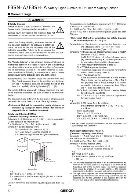
The "<strong>Safety</strong> distance" is the minimum distance that must be<br />
maintained between the <strong>F3SN</strong>-A/F3SH-A and a hazardous<br />
part of a machine in order to stop the machine before someone<br />
or something reaches it. The safety distance is calculated<br />
based on the following equation when a person moves<br />
perpendicular to the detection zone of a light curtain.<br />
<strong>Safety</strong> distance (S) = Intrusion speed into the detection zone<br />
(K) × Total response time for the machine and light curtain<br />
(T) + Additional distance calculated based on the<br />
detection capability of the light curtain (C) ......(1)<br />
The safety distance varies with national standards and individual<br />
machine standards. Be sure to refer to related standards.<br />
The equation is also different if the direction of intrusion is not<br />
perpendicular to the detection zone of the light curtain.<br />
Method for calculating safety distance as<br />
provided by European Norm EN999 (for intrusion<br />
perpendicular to the detection zone)<br />
<strong>Safety</strong> <strong>Light</strong> <strong>Curtain</strong> <strong>F3SN</strong>-A<br />
[Detection capability: 40mm or less]<br />
Substitute K = 2,000 mm/s and C = 8 (d − 14 mm) in equation<br />
(1) and calculate as shown below.<br />
S = 2,000 mm/s × (Tm + Ts) + 8 (d − 14 mm) ......(2)<br />
Where: S = <strong>Safety</strong> distance (mm)<br />
Tm = Machine response time (s) ∗1<br />
Ts = <strong>Light</strong> curtain response time (s) ∗2<br />
d = Detection capability of the light curtain (mm)<br />
Hazardous part<br />
WARNING<br />
<strong>Safety</strong> distance<br />
Detection zone<br />
Beam center-line<br />
Intrusion direction<br />
e.g.:<br />
Tm = 0.05 s, Ts = 0.01 s, d =14 mm:<br />
S = 2,000 mm/s × (0.05 s + 0.01 s) + 8 (14 mm − 14 mm)<br />
= 120 mm<br />
Use S = 100 mm if the result of equation (2) is less than 100<br />
mm.<br />
Recalculate using the following equation with K = 1,600 mm/s<br />
if the result is over 500 mm.<br />
S = 1,600 mm/s × (Tm + Ts) + 8 (d − 14 mm) ......(3)<br />
Use S = 500 mm if the result from equation (3) is less than<br />
500 mm.<br />
Method for calculating the safety distance<br />
as provided by ANSI B11.19 (US)<br />
<strong>Safety</strong> distance (S) = Intrusion speed into the detection zone<br />
(K) × Response time (Ts + Tc + Tr + Tbm)<br />
+ Additional distance (Dpf) ......(5)<br />
Where: K = Intrusion speed (Recommended value in OSHA<br />
standards is 1,600 mm/s)<br />
ANSI B11.19. does not define Intrusion speed<br />
(K). When determining K, consider possible factors<br />
including physical ability of operators.<br />
Ts = Time required for machine to stop (s)<br />
Tr = <strong>F3SN</strong>-A response time (s) ∗<br />
Tc = Maximum response time required for machine<br />
control circuit to apply brake (s)<br />
Tbm = Additional time (s)<br />
If the machine is provided with a brake monitor,<br />
Tbm = brake monitor setting time − (Ts + Tc). If<br />
not provided with a brake monitor, it is recommended<br />
to determine a value more than 20% of<br />
(Ts + Tc) as the additional time.<br />
Dpf = Additional distance. Dpf is calculated as follows<br />
based on ANSI standards.<br />
Dpf = 3.4 × (d − 7.0): d is the detection capability of<br />
the light curtain (mm).<br />
e.g.:<br />
Where: K = 1,600 mm/s, Ts + Tc = 0.06 s,<br />
Brake monitor setting time = 0.1 s, Tr = 0.1 s,<br />
d = 14 mm,<br />
From equation (5):<br />
Tbm = 0.1 − 0.06 = 0.04 s<br />
Dpf = 3.4 × (14 − 7.0) = 23.8 mm<br />
S = 1,600 × (0.06 + 0.1 − 0.04) + 23.8 = 215.8 mm<br />
∗ The light curtain response time refers to the time required for output<br />
to change from ON to OFF.<br />
<strong>Multi</strong>-<strong>beam</strong> <strong>Safety</strong> <strong>Sensor</strong> F3SH-A<br />
[Detection capability: over 40mm]<br />
Substitute K = 1,600 mm/s and C = 850 mm in equation (1)<br />
and calculate as shown below.<br />
S = 1,600 mm/s × (Tm + Ts) + 850 ......(4)<br />
Where: S = <strong>Safety</strong> distance (mm)<br />
Tm = Machine response time (s) ∗1<br />
Ts = <strong>Light</strong> curtain response time (s) ∗2<br />
e.g.:<br />
Tm = 0.05 s, Ts = 0.01 s:<br />
S = 1,600 mm/s × (0.05 s + 0.01 s) + 850 mm<br />
= 946 mm<br />
∗1. The machine response time refers to the maximum time from the<br />
moment the machine receives a stop signal to the moment the<br />
hazardous part of the machine stops. The machine response<br />
time should be measured on actual machines. The machine<br />
response time should be measured and confirmed periodically.<br />
∗2. The light curtain response time refers to the time required for output<br />
to change from ON to OFF. When using a Controller, add the<br />
response time for the Controller to the response time for the<br />
<strong>Sensor</strong> (see above) when calculating the safe distance.<br />
12