Safety Light Curtain / Multi-beam Safety Sensor F3SN-A ... - Omron
Safety Light Curtain / Multi-beam Safety Sensor F3SN-A ... - Omron
Safety Light Curtain / Multi-beam Safety Sensor F3SN-A ... - Omron

Create successful ePaper yourself
Turn your PDF publications into a flip-book with our unique Google optimized e-Paper software.
<strong>F3SN</strong>-A/F3SH-A <strong>Safety</strong> <strong>Light</strong> <strong>Curtain</strong>/<strong>Multi</strong>-<strong>beam</strong> <strong>Safety</strong> <strong>Sensor</strong><br />
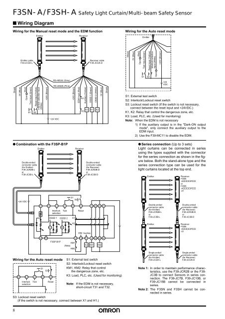
■ Wiring Diagram<br />
Wiring for the Manual reset mode and the EDM function<br />
Emitter<br />
Receiver<br />
Wiring for the Auto reset mode<br />
Emitter<br />
Emitter cable<br />
F39-JC A-L<br />
Receiver cable<br />
F39-JC A-D<br />
Shield<br />
0V (Blue)<br />
(Red)<br />
Open<br />
Test input (Green)<br />
Reset input (Yellow)<br />
Interlock selection<br />
input (White)<br />
+24V (Brown)<br />
S1<br />
S3<br />
Open<br />
Shield<br />
0V (Blue)<br />
(Red)<br />
Open<br />
Test input (Green)<br />
S1<br />
Reset input (Yellow)<br />
S2<br />
Interlock selection input<br />
(White)<br />
+24V (Brown)<br />
RS-485(A) (Gray)<br />
RS-485(B) (Pink)<br />
+24 VDC<br />
+24V (Brown)<br />
EDM input (Red)<br />
K1<br />
Auxiliary (Yellow)<br />
OSSD 1 (Green)<br />
OSSD 2 (White)<br />
0V (Blue)<br />
K3 K1 K2<br />
K2<br />
Shield<br />
+24<br />
VDC<br />
S1: External test switch<br />
S2: Interlock/Lockout reset switch<br />
S3: Lockout reset switch (If the switch is not necessary,<br />
connect between the reset input and +24VDC.)<br />
K1, K2: Relay that control the dangerous zone, etc.<br />
K3: Load, PLC, etc. (Used for monitoring)<br />
Note: When the EDM is not necessary<br />
1) If the auxiliary output is in the "Dark-ON output<br />
mode", only connect the auxiliary output to the<br />
EDM input.<br />
2) Use the F39-MC11 to disable the EDM.<br />
● Combination with the F3SP-B1P<br />
Double-ended<br />
connector cable<br />
(for Emitter)<br />
F39-JCR2B-L<br />
or<br />
F39-JC3B-L<br />
Emitter<br />
Receiver<br />
Double-ended<br />
connector cable<br />
(for Receiver)<br />
F39-JCR2B-D<br />
or<br />
F39-JC3B-D<br />
● Series connection (Up to 3 sets)<br />
<strong>Light</strong> curtains can be connected in series<br />
using the types supplied with the connector<br />
for the series connection as shown in the figure<br />
below. Both the stand-alone type and the<br />
series connection type can be used for the<br />
light curtains located at the top end.<br />
Emitter<br />
Receiver<br />
<strong>F3SN</strong><br />
-A P<br />
or<br />
<strong>F3SN</strong><br />
-A P<br />
-01<br />
+24 VDC<br />
A1<br />
H1<br />
L1<br />
Interlock<br />
selection<br />
J1<br />
Test<br />
OSSD 1 OSSD 2<br />
S1<br />
S2<br />
H1<br />
K1<br />
X1<br />
Reset<br />
13<br />
23<br />
33<br />
41<br />
Double-ended<br />
connector cable<br />
(for Emitter)<br />
F39-JCR2B-L<br />
or<br />
F39-JC3B-L<br />
Double-ended<br />
connector cable<br />
(for Receiver)<br />
F39-JCR2B-D<br />
or<br />
F39-JC3B-D<br />
K1<br />
K2<br />
K2<br />
EDM Auxiliary<br />
Emitter<br />
Receiver<br />
<strong>F3SN</strong><br />
-A P<br />
-01<br />
A2<br />
PE<br />
F3SP-B1P<br />
Wiring for the Auto reset mode<br />
H1<br />
L1<br />
Interlock<br />
selection<br />
J1<br />
Test<br />
S1<br />
S3<br />
H1 X1<br />
Reset<br />
T31<br />
KM1<br />
(Note)<br />
KM2<br />
T32<br />
P1<br />
K3<br />
14<br />
KM1<br />
24<br />
34<br />
KM2<br />
S1: External test switch<br />
S2: Interlock/Lockout reset switch<br />
KM1, KM2: Relay that control<br />
the dangerous zone, etc.<br />
K3: Load, PLC, etc. (Used for monitoring)<br />
Note: If the EDM is not necessary,<br />
short-circuit T31 and T32.<br />
S3: Lockout reset switch<br />
(If the switch is not necessary, connect between X1 and H1.)<br />
42<br />
Single-ended<br />
connector cable<br />
(for Emitter)<br />
F39-JC A-L<br />
Single-ended<br />
connector cable<br />
(for Receiver)<br />
F39-JC A-D<br />
Note 1: In order to maintain performance characteristics,<br />
use the F39-JCR2B or the F39-<br />
JC3B to connect <strong>Sensor</strong>s in series connection.<br />
The F39-JC7B, F39-JC10B, or<br />
F39-JC15B cannot be connected in<br />
series.<br />
Note 2: The <strong>F3SN</strong> and F3SH cannot be connected<br />
in series.<br />
8