Safety Light Curtain / Multi-beam Safety Sensor F3SN-A ... - Omron
Safety Light Curtain / Multi-beam Safety Sensor F3SN-A ... - Omron
Safety Light Curtain / Multi-beam Safety Sensor F3SN-A ... - Omron

You also want an ePaper? Increase the reach of your titles
YUMPU automatically turns print PDFs into web optimized ePapers that Google loves.
<strong>Safety</strong> <strong>Light</strong> <strong>Curtain</strong>/<strong>Multi</strong>-<strong>beam</strong> <strong>Safety</strong> <strong>Sensor</strong> <strong>F3SN</strong>-A/F3SH-A<br />
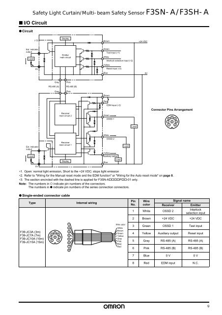
■ I/O Circuit<br />
● Circuit<br />
(∗3)<br />
Display<br />
Brown<br />
2<br />
+24 VDC<br />
Ext. indicator<br />
output<br />
Load<br />
4<br />
Emitter<br />
main circuit<br />
Green<br />
3<br />
Test input (∗1)<br />
White<br />
1<br />
Interlock selection input (∗2)<br />
7<br />
0V<br />
Yellow<br />
4<br />
Reset input (∗2)<br />
Blue<br />
7<br />
0V<br />
5<br />
Gray<br />
RS-485 (A)<br />
6<br />
Pink<br />
RS-485 (B)<br />
Gray<br />
5<br />
Pink<br />
6<br />
Brown<br />
2<br />
Receiver<br />
main circuit 2<br />
Red<br />
8<br />
EDM input (∗2)<br />
Green<br />
3<br />
OSSD 1<br />
Load<br />
Connector Pins Arrangement<br />
5<br />
6<br />
7 8<br />
1<br />
4<br />
3<br />
2<br />
Ext. indicator<br />
output<br />
Load<br />
8<br />
7<br />
0V<br />
Receiver<br />
main circuit 1<br />
Display<br />
White<br />
1<br />
OSSD 2<br />
Yellow<br />
4<br />
Auxiliary output<br />
Load<br />
Blue<br />
7<br />
∗1. Open: normal light emission, Short to the +24 VDC: stops light emission<br />
∗2. Refer to "Wiring for the Manual reset mode and the EDM function" or "Wiring for the Auto reset mode" on page 8.<br />
∗3. The section encircled with the dashed line is applied for <strong>F3SN</strong>-A!!!!P!!-01 only.<br />
Note: The numbers in " indicate pin numbers of the connectors.<br />
The numbers in ● indicate pin numbers of the series connection connectors.<br />
Load<br />
● Single-ended connector cable<br />
Type<br />
Internal wiring<br />
Pin<br />
No.<br />
Wire<br />
color<br />
Signal name<br />
Receiver<br />
Emitter<br />
1 White OSSD 2<br />
Interlock<br />
selection input<br />
2 Brown +24 VDC +24 VDC<br />
F39-JC3A (3m)<br />
F39-JC7A (7m)<br />
F39-JC10A (10m)<br />
F39-JC15A (15m)<br />
5<br />
4 6<br />
3 8 7<br />
2 1<br />
1<br />
2<br />
3<br />
4<br />
5<br />
6<br />
7<br />
8<br />
Wire color<br />
White<br />
Brown<br />
Green<br />
Yellow<br />
Gray<br />
Pink<br />
Blue<br />
Red<br />
3 Green OSSD 1 Test input<br />
4 Yellow Auxiliary output Reset input<br />
5 Gray RS-485 (A) RS-485 (A)<br />
6 Pink RS-485 (B) RS-485 (B)<br />
7 Blue 0 V 0 V<br />
8 Red EDM input N.C.<br />
9