Safety Light Curtain / Multi-beam Safety Sensor F3SN-A ... - Omron
Safety Light Curtain / Multi-beam Safety Sensor F3SN-A ... - Omron
Safety Light Curtain / Multi-beam Safety Sensor F3SN-A ... - Omron

You also want an ePaper? Increase the reach of your titles
YUMPU automatically turns print PDFs into web optimized ePapers that Google loves.
<strong>Safety</strong> <strong>Light</strong> <strong>Curtain</strong>/<strong>Multi</strong>-<strong>beam</strong> <strong>Safety</strong> <strong>Sensor</strong> <strong>F3SN</strong>-A/F3SH-A<br />
■ Correct Usage<br />
WARNING<br />
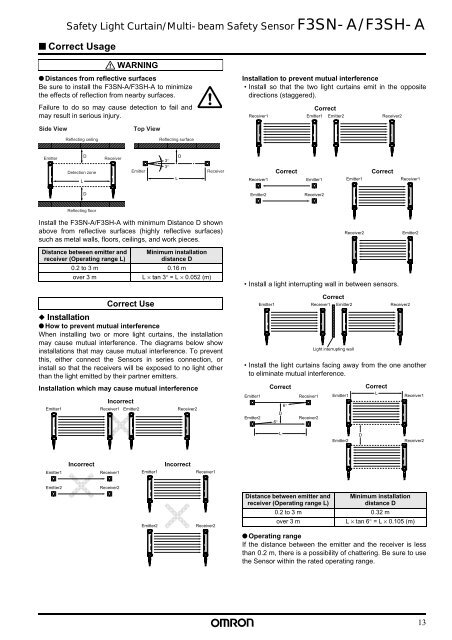
● Distances from reflective surfaces<br />
Be sure to install the <strong>F3SN</strong>-A/F3SH-A to minimize<br />
the effects of reflection from nearby surfaces.<br />
Failure to do so may cause detection to fail and<br />
may result in serious injury.<br />
Installation to prevent mutual interference<br />
• Install so that the two light curtains emit in the opposite<br />
directions (staggered).<br />
Receiver1<br />
Correct<br />
Emitter1<br />
Emitter2<br />
Receiver2<br />
Side View<br />
Reflecting ceiling<br />
Top View<br />
Reflecting surface<br />
Emitter<br />
L<br />
D<br />
Detection zone<br />
Receiver<br />
Emitter<br />
3°<br />
3°<br />
L<br />
D<br />
Receiver<br />
Receiver1<br />
Correct<br />
Emitter1<br />
Emitter1<br />
Correct<br />
Receiver1<br />
D<br />
Emitter2<br />
Receiver2<br />
Reflecting floor<br />
Install the <strong>F3SN</strong>-A/F3SH-A with minimum Distance D shown<br />
above from reflective surfaces (highly reflective surfaces)<br />
such as metal walls, floors, ceilings, and work pieces.<br />
Distance between emitter and<br />
receiver (Operating range L)<br />
Minimum installation<br />
distance D<br />
0.2 to 3 m 0.16 m<br />
over 3 m<br />
L × tan 3° = L × 0.052 (m)<br />
Receiver2<br />
• Install a light interrupting wall in between sensors.<br />
Emitter2<br />
Correct Use<br />
◆ Installation<br />
● How to prevent mutual interference<br />
When installing two or more light curtains, the installation<br />
may cause mutual interference. The diagrams below show<br />
installations that may cause mutual interference. To prevent<br />
this, either connect the <strong>Sensor</strong>s in series connection, or<br />
install so that the receivers will be exposed to no light other<br />
than the light emitted by their partner emitters.<br />
Installation which may cause mutual interference<br />
Emitter1<br />
Incorrect<br />
Receiver1<br />
Emitter2<br />
Receiver2<br />
• Install the light curtains facing away from the one another<br />
to eliminate mutual interference.<br />
Emitter1<br />
Emitter2<br />
Emitter1<br />
Correct<br />
D<br />
6°<br />
6°<br />
Receiver1<br />
Receiver2<br />
Receiver1<br />
Correct<br />
Emitter2<br />
<strong>Light</strong> interrupting wall<br />
Emitter1<br />
Correct<br />
L<br />
Receiver2<br />
Receiver1<br />
L<br />
Emitter2<br />
D<br />
Receiver2<br />
Emitter1<br />
Incorrect<br />
Receiver1<br />
Emitter1<br />
Incorrect<br />
Receiver1<br />
Emitter2<br />
Receiver2<br />
Emitter2<br />
Receiver2<br />
Distance between emitter and<br />
receiver (Operating range L)<br />
Minimum installation<br />
distance D<br />
0.2 to 3 m 0.32 m<br />
over 3 m<br />
L × tan 6° = L × 0.105 (m)<br />
● Operating range<br />
If the distance between the emitter and the receiver is less<br />
than 0.2 m, there is a possibility of chattering. Be sure to use<br />
the <strong>Sensor</strong> within the rated operating range.<br />
13