New Aspects of Monitoring with a CMOS camera for ... - Prometec
New Aspects of Monitoring with a CMOS camera for ... - Prometec
New Aspects of Monitoring with a CMOS camera for ... - Prometec

Create successful ePaper yourself
Turn your PDF publications into a flip-book with our unique Google optimized e-Paper software.
Published at ICALEO‘02 (Welding Monitor PD 2000)<br />
<strong>New</strong> <strong>Aspects</strong> <strong>of</strong> <strong>Monitoring</strong> <strong>with</strong> a <strong>CMOS</strong><br />
<strong>camera</strong> <strong>for</strong> Laser Materials Processing<br />
Joerg Beersiek<br />
PROMETEC GmbH, Aachen, Germany<br />
1. Abstract<br />
A new system <strong>for</strong> process monitoring <strong>of</strong> laser beam welding based on a<br />
<strong>CMOS</strong>-<strong>camera</strong> was presented in <strong>for</strong>mer presentations [1,2]. The system observes<br />
the welding process online and coaxial to the laser beam. Until now we have got<br />
various experiences <strong>with</strong> this system in industrial applications and experimental<br />
trials.<br />
For example the system yields interesting results <strong>for</strong> cutting processes <strong>with</strong><br />
regard to incomplete cut and development <strong>of</strong> dross.<br />
Another application will show the availability <strong>of</strong> the system <strong>for</strong> welding in the<br />
automotive industry. One <strong>of</strong> the most interesting processes in this industry is the<br />
welding <strong>of</strong> zinc coated steel sheet in an overlapped joint configuration. Due to<br />
the low evaporation temperature <strong>of</strong> zinc, it is necessary to weld this material<br />
<strong>with</strong> a defined gap between the two plates. Recorded films are analyzed and<br />
some effects as a consequence <strong>of</strong> different gap widths are presented in the films.<br />
The films and the resulting curves show the possibility to monitor certain weld<br />
failures, caused by different gaps in between the joint.<br />
2. Introduction<br />
The answer <strong>of</strong> the workpiece interacting <strong>with</strong> a high power<br />
laser is a strong emission <strong>of</strong> secondary radiation. This radiation<br />
carries in<strong>for</strong>mation about the dynamics <strong>of</strong> the laser process and<br />
the quality <strong>of</strong> the resulting weld seam or cutting kerf [3].<br />
The secondary radiation is used by a lot <strong>of</strong> optical sensor<br />
devices to monitor the working process.<br />
The most frequently used system in research and commercially<br />
available process diagnostic systems [3] is a photo diode <strong>with</strong> optical<br />
filters delimiting the detected radiation to a certain spectral<br />
range. The advantages <strong>of</strong> such detectors are high temporal resolution<br />
<strong>of</strong> the recorded signals and a low price compared to<br />
other devices like spectrographs or <strong>camera</strong>s. A disadvantage <strong>of</strong><br />
the photo detector is its one-dimensional view (i.e. spatially integrating<br />
the signal) <strong>of</strong> the process which limits the signal evaluation<br />
to an amplitude and frequency analysis <strong>of</strong> the recorded<br />
data.<br />
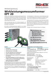
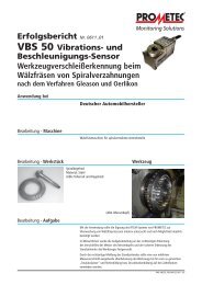
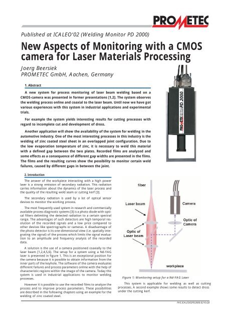
A solution is the use <strong>of</strong> a <strong>camera</strong> positioned coaxially to the<br />
laser beam [1,2,4,5,6]. The setup <strong>for</strong> a system using a Nd-YAG<br />
laser is presented in figure 1. This is an exceptional position <strong>for</strong><br />
the <strong>camera</strong> because it is possible to obtain in<strong>for</strong>mation from the<br />
inner parts <strong>of</strong> the keyhole. The s<strong>of</strong>tware <strong>of</strong> the <strong>camera</strong> evaluates<br />
different failures and process parameters online <strong>with</strong> the help <strong>of</strong><br />
characteristic regions <strong>with</strong>in the image <strong>of</strong> the <strong>camera</strong>. Today this<br />
system is used in industrial applications to monitor welding<br />
processes.<br />
However it is possible to use the recorded films to analyze the<br />
process and to improve process parameters. These possibilities<br />
are described in the following chapters using an example <strong>for</strong> the<br />
welding <strong>of</strong> zinc coated steel.<br />
Figure 1: <strong>Monitoring</strong> setup <strong>for</strong> a Nd-YAG Laser<br />
This system is applicable <strong>for</strong> welding as well as cutting<br />
processes. A second example shows some results to detect dross<br />
under the cutting kerf.<br />
PVE.ICALEO02PD2000.0210.GB
Published at ICALEO‘02 (Welding Monitor PD 2000)<br />
3. Observation <strong>of</strong> zinc coated steel sheets<br />
The welding <strong>of</strong> zinc coated steel in an overlapped joint is difficult.<br />
Due to the lower boiling point <strong>of</strong> zinc (~900 °C) in comparison<br />
to the melting point <strong>of</strong> steel (~1530 °C) the heating <strong>of</strong><br />
the workpiece induces blowholes in the weld, if no gap is present<br />
between the two sheets. The gap enables the evaporated<br />
zinc to exhaust from the interaction zone.<br />
On the other hand if the gap becomes too wide the connection<br />
between the two plates will be lost. However, to make sure<br />
that the gap has the specified value, it is necessary to monitor<br />
the process <strong>with</strong> respect to the gap width.<br />
This article will discuss one effect, which could be dangerous<br />
<strong>for</strong> the weld quality <strong>of</strong> such lap joints. Under normal conditions<br />
a small gap is useful <strong>for</strong> the process as described be<strong>for</strong>e and only<br />
one keyhole and meltpool is <strong>for</strong>med in the interaction zone. This<br />
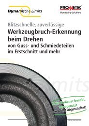
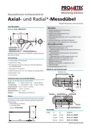
situation is sketched on the left side <strong>of</strong> figure 2. Additionally a<br />
typical picture from the coaxial adopted <strong>camera</strong> (figure 1) is presented<br />
in figure 2. A green circle in front <strong>of</strong> the keyhole can be<br />
recognized in the picture. It shows the combustion front <strong>of</strong> the<br />
zinc on the upper surface <strong>of</strong> the plate. The green region behind<br />
this circle depicts <strong>for</strong> the whole keyhole. In the center <strong>of</strong> the keyhole<br />
region an intensity minimum is visible. This minimum stands<br />
<strong>for</strong> full penetration. This effect is well documented in <strong>for</strong>mer<br />
papers [1,5].<br />
weld is <strong>with</strong>out visible failures when viewed from above and<br />
below.<br />
In figure 2 the image on the right side presents a typical picture<br />
from the coaxial <strong>camera</strong> system <strong>for</strong> this situation. Instead <strong>of</strong><br />
the intensity minimum in the center <strong>of</strong> the keyhole a small<br />
intensity peak is observed and correlates <strong>with</strong> this situation. The<br />
interpretation <strong>of</strong> this result is that the <strong>camera</strong> looks through the<br />
keyhole in the upper plate <strong>of</strong> the workpiece and observes the<br />
second keyhole in the plate below. We use this effect to monitor<br />
the process <strong>with</strong> our system.<br />
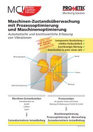
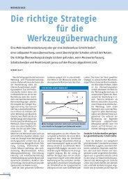
An algorithm was applied, which is able to find this peak in<br />
the image <strong>of</strong> the keyhole. The time resolved curve is presented<br />
in figure 3. Excluding the start situation the algorithm shows a<br />
strong correlation <strong>with</strong> the effect <strong>of</strong> not connected plates.<br />
Figure 2: welding <strong>of</strong> zinc coated steel <strong>with</strong> different gaps<br />
The connection <strong>of</strong> the two plates fails, when the gap width<br />
increases to a point when there is not enough melt to bridge the<br />
gap. In most cases the upper meltpool collapses under these conditions.<br />
The resulting weld seam is disturbed and after welding<br />
a strong deterioration<br />
<strong>of</strong> weld quality is<br />
obvious.<br />
Sometimes the<br />
welding conditions<br />
are similar to the situation<br />
described on<br />
the right side <strong>of</strong> figure<br />
2. The gap is just<br />
wide enough to loose<br />
contact between the<br />
2 meltpools <strong>of</strong> the<br />
two plates and the<br />
laser beam is strong<br />
enough to produce<br />
two different welding<br />
processes on both<br />
plates <strong>with</strong>out <strong>of</strong> any<br />
connection. This is a<br />
very difficult situation<br />
<strong>for</strong> the user because<br />
the quality <strong>of</strong> the<br />
Figure 3: time resolved search <strong>for</strong> the peak in the center <strong>of</strong><br />
the keyhole<br />
4. <strong>Monitoring</strong> <strong>of</strong> dross during a cutting process<br />
Another possible application <strong>for</strong> a coaxial monitoring system<br />
is the cutting process. An example is presented in this paper,<br />
which shows the influence <strong>of</strong> dross under the cutting kerf on the<br />
images observed <strong>with</strong> our <strong>camera</strong>.<br />
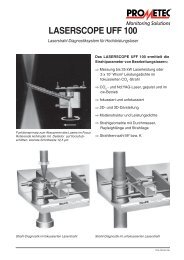
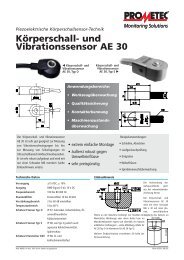
The application uses a CO 2 -Laser <strong>with</strong> a ZnSe-lens as the optic<br />
<strong>for</strong> the laser beam (figure 4). Hence, the <strong>camera</strong> looks through a<br />
plate, which is transparent <strong>for</strong> light <strong>with</strong> a wavelength higher<br />
than 550 nm and reflects light <strong>of</strong> the CO 2 - Laser beam. Under<br />
these conditions the optic <strong>of</strong> the <strong>camera</strong> is a combination <strong>of</strong> the<br />
ZnSe-lens and the lens <strong>of</strong> the <strong>camera</strong>.<br />
Figure 4: <strong>Monitoring</strong> setup <strong>for</strong> cutting <strong>with</strong> a CO 2 -laser beam and a ZnSe-optic<br />
The application is the<br />
automatic production <strong>of</strong><br />
models <strong>for</strong> a specified<br />
subject like car bodies.<br />
The model will be<br />
<strong>for</strong>med by plates lying on<br />
top <strong>of</strong> each other. Under<br />
these circumstances dross<br />
will disturb the <strong>for</strong>m <strong>of</strong><br />
the stacked plates and<br />
inevitably the model<br />
itself. This guideline<br />
makes a monitoring system<br />
necessary to ensure a<br />
process <strong>with</strong>out <strong>of</strong> dross.<br />
Our procedure to find<br />
a possibility to monitor a<br />
new process (like cutting)<br />
is, to analyze films, which<br />
correlate <strong>with</strong> the specified<br />
process attribute.<br />
The first step is to record<br />
PVE.ICALEO02PD2000.0210.GB
Published at ICALEO‘02 (Welding Monitor PD 2000)<br />
Figure 5: Images <strong>with</strong> changing gas pressure<br />
a film while cutting <strong>with</strong> process parameters producing<br />
dross and compare the images <strong>with</strong> images from a cutting<br />
process <strong>with</strong>out dross.<br />
The most significant process parameter to produce<br />
dross is the pressure <strong>of</strong> the cutting gas. Some typical<br />
images are presented in figure 5 under different pressure<br />
conditions. Other process parameters are kept constant. It<br />
is obvious that the intensity in the center <strong>of</strong> the image<br />
increases <strong>with</strong> decreasing pressure <strong>of</strong> the cutting gas. This<br />
effect correlates <strong>with</strong> the probability to produce dross.<br />
The breakpoint is close to 8 bar. A cut <strong>with</strong> 6 bar gas pressure<br />
produces dross everywhere.<br />
The interpretation <strong>of</strong> these images is that <strong>with</strong> decreasing<br />
gas pressure the thickness <strong>of</strong> the melt at the cutting<br />
front increases. With this the source <strong>of</strong> the radiation<br />
increases and more molten material is present to produce dross.<br />
The images show the possibility to detect dross <strong>for</strong>mation by<br />
the intensity <strong>of</strong> the center <strong>of</strong> the cutting process. Based on these<br />
results an algorithm which uses a histogram <strong>of</strong> the pictures in<br />
the region <strong>of</strong> the cutting front was selected to analyze the<br />
process.<br />
In figure 6 three typical histograms from the pictures <strong>with</strong><br />
changing gas pressure are presented. The most obvious change<br />
in the histograms is the shift <strong>of</strong> the maximum to higher values if<br />
Figure 6: Histogram Analysis<br />
gas pressure decreases. There<strong>for</strong>e an algorithm was developed,<br />
which looks <strong>for</strong> the maximum <strong>with</strong>in the histogram. This algorithm<br />
was used to make a time resolved analysis <strong>of</strong> the working<br />
process. In figure 7 a typical result <strong>for</strong> the time resolved analysis<br />
is presented. An octagon was cut and from one side the kerf<br />
<strong>with</strong> the resulting analysis <strong>of</strong> the recorded film is presented. The<br />
correlation <strong>of</strong> the signal <strong>with</strong> the kerf is obvious and a future<br />
monitoring system can use this result <strong>with</strong> a limit to detect dross<br />
or no dross.<br />
Figure 7: Time resolved Analysis<br />
PVE.ICALEO02PD2000.0210.GB
Published at ICALEO‘02 (Welding Monitor PD 2000)<br />
5. Conclusion<br />
Two new aspects <strong>of</strong> monitoring material processing <strong>with</strong> a<br />
<strong>camera</strong> positioned coaxial to the laserbeam are presented in this<br />
article.<br />
In the first part results <strong>of</strong> welding zinc coated steel are presented.<br />
Due to the evaporation temperature <strong>of</strong> zinc, zinc coated<br />
steel in an overlapped joint will be welded normally <strong>with</strong> gap<br />
between the two plates.<br />
If the gap width becomes to wide the connection <strong>of</strong> the two<br />
plates is lost and two separate seams are <strong>for</strong>med in the upper<br />
and in the lower plate, which appear visually to be good. This<br />
phenomena could be detected using the <strong>camera</strong> based system.<br />
The second part shows a cutting application. The task is the<br />
observation <strong>of</strong> dross. Dross <strong>for</strong>mation can be intensified if the<br />
pressure <strong>of</strong> the cutting gas decreases. This results in a higher<br />
intensity directly at the cutting front, which can be used to monitor<br />
the cutting process <strong>for</strong> dross <strong>for</strong>mation.<br />
6. References<br />
[1] J. Beersiek<br />
A <strong>CMOS</strong> <strong>camera</strong> as a tool <strong>for</strong> process analysis not only <strong>for</strong> laserbeam<br />
welding<br />
ICALEO 2001, Section F206<br />
[2] J. Beersiek<br />
On-line monitoring <strong>of</strong> Keyhole Instabilities during Laser Beam<br />
Welding<br />
ICALEO 99, Section D, pp. 49-58<br />
[3] A. Sun, E. Kannatey-Asibu, Jr., M. Gartner<br />
Sensor systems <strong>for</strong> real-time monitoring <strong>of</strong> laserweld quality<br />
Journal <strong>of</strong> Laser Applications, Volume 11, Number 4, pp. 153-168,<br />
1999<br />
[4] J. Beersiek, R. Poprawe, W. Schulz, H. Gu, R.E. Mueller, W.W. Duley<br />
On-line monitoring <strong>of</strong> penetration depth in laser beam welding<br />
ICALEO 97, Section E<br />
[5] Abels P., Kaierle S., Kratzsch C.<br />
Universal coaxial process control system <strong>for</strong> laser materials processing<br />
ICALEO 99, Section E, pp 99-108<br />
[6] S. Kaierle, P. Abels, G. Kapper, C. Kratzsch, J. Michel, W. Schulz, R.<br />
Poprawe<br />
State <strong>of</strong> the Art and <strong>New</strong> Advances in Process Control <strong>for</strong> Laser<br />
Materials Processing<br />
Proc. ICALEO 2001, Section E<br />
Subject to technical modifications ©2002 PROMETEC<br />
PROMETEC GmbH<br />
Juelicher Str. 338<br />
D-52070 Aachen<br />
www.prometec.com<br />
Phone: +49/241/16609-0<br />
Fax: +49/241/16609-50<br />
prometec-de@prometec.com<br />
<strong>Monitoring</strong> <strong>of</strong> Machines,<br />
Processes, Tools and Lasers<br />
Subsidiary companies and representations<br />
in Europe, America and Asia<br />
PVE.ICALEO02PD2000.0210.GB<br />
Your Representative :