practical applications of in-process monitoring for laser ... - Prometec
practical applications of in-process monitoring for laser ... - Prometec
practical applications of in-process monitoring for laser ... - Prometec

You also want an ePaper? Increase the reach of your titles
YUMPU automatically turns print PDFs into web optimized ePapers that Google loves.
Proceed<strong>in</strong>gs <strong>of</strong> the 23 rd International Congress on Applications <strong>of</strong> Lasers and Electro-Optics 2004<br />
PRACTICAL APPLICATIONS OF IN-PROCESS MONITORING FOR LASER PROCESSES -<br />
NOT ONLY FOR SINGLE WELDS AND COMMON MATERIALS.<br />
Joerg Beersiek 1 , Thomas Devermann 1 , Klaus Behler 2<br />
1<br />
PROMETEC GmbH, Jülicher Str. 338, 52070 Aachen, Germany<br />
2 University <strong>of</strong> Applied Sciences, Wiesenstr. 14, 35390 Gießen-Friedberg, Germany<br />
Abstract/Manuscript<br />
Laser weld<strong>in</strong>g is by now a conventional <strong>in</strong>dustrial<br />
technology. Besides the prevalent <strong>process</strong>es to<br />
manufacture s<strong>in</strong>gle welds and endless seams more<br />
complex weld operations <strong>in</strong>volv<strong>in</strong>g multiple welds<br />
with differ<strong>in</strong>g jo<strong>in</strong>t designs <strong>in</strong> one work piece are<br />
becom<strong>in</strong>g common. Monitor<strong>in</strong>g <strong>of</strong> such parts require<br />
the weld monitor<strong>in</strong>g systems to <strong>of</strong>fer easily<br />
manageable solutions. For welded parts whose<br />
function is imperative <strong>for</strong> the secure operation <strong>of</strong><br />
systems, the secure <strong>in</strong>-<strong>process</strong> judgment <strong>of</strong> weld<br />
<strong>process</strong> quality is <strong>in</strong>dispensable.<br />
This paper discusses the functionality <strong>of</strong> a CMOS<br />
camera based monitor<strong>in</strong>g system <strong>for</strong> such purposes<br />
with help <strong>of</strong> case studies from e.g. the automotive<br />
<strong>in</strong>dustry. The basic work<strong>in</strong>g pr<strong>in</strong>ciple <strong>of</strong> this system<br />
<strong>for</strong> the monitor<strong>in</strong>g <strong>of</strong> <strong>laser</strong> <strong>process</strong>es has been<br />
published <strong>in</strong> <strong>for</strong>mer presentations.<br />
The way <strong>of</strong> solv<strong>in</strong>g unique monitor<strong>in</strong>g tasks with the<br />
system is presented us<strong>in</strong>g <strong>practical</strong> examples. These<br />
examples show the capabilities <strong>of</strong> a camera based<br />
<strong>process</strong> monitor<strong>in</strong>g system like geometrical resolution,<br />
adaptable algorithms and <strong>in</strong>dependence <strong>of</strong> the weld<strong>in</strong>g<br />
direction.<br />
Pos.<br />
Sketch<br />
Description <strong>of</strong> the<br />
Application<br />
Material<br />
Jo<strong>in</strong>t<br />
configuration<br />
Type <strong>of</strong><br />
Mach<strong>in</strong>e<br />
Type <strong>of</strong><br />
Laser<br />
Power<br />
Range<br />
Monitor<strong>in</strong>g<br />
Task(s)<br />
Interface<br />
User<br />
1<br />
Weld<strong>in</strong>g <strong>of</strong> thick<br />
section steel beams<br />
synchronal with two<br />
<strong>process</strong><strong>in</strong>g heads <strong>in</strong> a<br />
T-jo<strong>in</strong>t configuration<br />
Mild steel<br />
Double Fillet jo<strong>in</strong>t<br />
Special weld<strong>in</strong>g<br />
mach<strong>in</strong>e with two<br />
<strong>process</strong><strong>in</strong>g heads<br />
CO2-<strong>laser</strong><br />
12 kW<br />
Laser beam<br />
position with<br />
regard to the<br />
jo<strong>in</strong>t; Penetration<br />
depth<br />
Pr<strong>of</strong>ibus<br />
Power plants<br />
2<br />
Endless weld<strong>in</strong>g <strong>of</strong><br />
pr<strong>of</strong>iles<br />
Mild steel,<br />
galvanized<br />
Lap jo<strong>in</strong>t<br />
Tube weld<strong>in</strong>g<br />
mach<strong>in</strong>e with dual<br />
focus<br />
CO2-<strong>laser</strong><br />
2 - 5 kW<br />
Penetration<br />
depth; Lack <strong>of</strong><br />
fusion; Focal<br />
position; Laser<br />
power<br />
Pr<strong>of</strong>ibus<br />
Automotive<br />
3<br />
Circumferential weld<br />
on gear parts<br />
High strength<br />
steel<br />
Butt jo<strong>in</strong>t<br />
Special weld<strong>in</strong>g<br />
mach<strong>in</strong>e with<br />
stationary<br />
<strong>process</strong><strong>in</strong>g head<br />
and rotary chuck<br />
Nd:YAG <strong>laser</strong> 1.5 - 2.5 kW<br />
Penetration<br />
depth; Part<br />
position; Weld<br />
<strong>of</strong>fset; Gas<br />
variations<br />
Pr<strong>of</strong>ibus<br />
Automotive<br />
4<br />
Various jo<strong>in</strong>ts on seat<br />
rails<br />
Mild Steel<br />
Fillet jo<strong>in</strong>ts, Butt<br />
jo<strong>in</strong>ts, Flare Bevel<br />
jo<strong>in</strong>t<br />
Robot <strong>laser</strong> weld<strong>in</strong>g<br />
Nd:YAG <strong>laser</strong><br />
cell<br />
3 kW<br />
Weld length,<br />
Laser power,<br />
Focal position,<br />
Gaps, Blow outs<br />
Pr<strong>of</strong>ibus<br />
Automotive<br />
5<br />
Heat Exchanger<br />
(Var. Types)<br />
Titanium,<br />
Hastaloy,<br />
Nickel etc.<br />
Overlap-Jo<strong>in</strong>ts<br />
Robot <strong>laser</strong><br />
weld<strong>in</strong>g cell<br />
Nd:YAG<br />
<strong>laser</strong><br />
3-4 kW<br />
Weld<strong>in</strong>g<br />
Speed, Laser<br />
Power, Focal<br />
Position, Gas<br />
Supply, Gaps<br />
Pr<strong>of</strong>ibus<br />
Var.<br />
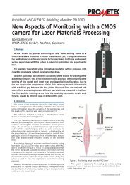
table 1<br />
Applications overview <strong>of</strong> the WELDING MONITOR PD2000
Introduction<br />
Today, the use <strong>of</strong> <strong>in</strong> <strong>process</strong> monitor<strong>in</strong>g systems is a<br />
common method to ensure quality <strong>in</strong> an <strong>in</strong>dustrial<br />
<strong>laser</strong> weld<strong>in</strong>g production <strong>process</strong>. There are lots <strong>of</strong><br />
different systems based on analysis <strong>of</strong> the radiation <strong>of</strong><br />
the plasma plume or analysis <strong>of</strong> the back reflection <strong>of</strong><br />
the <strong>laser</strong> light, or camera based systems, like the<br />
camera system <strong>of</strong> <strong>Prometec</strong>, which analyzes plasma<br />
and meltpool coaxial to the <strong>laser</strong> beam with a high<br />
spatial resolution.<br />
Today, the camera system is used <strong>for</strong> different<br />
<strong>applications</strong> and <strong>in</strong>tegrated <strong>in</strong> a number <strong>of</strong> production<br />
l<strong>in</strong>es. Some examples <strong>of</strong> different solved <strong>applications</strong><br />
are given <strong>in</strong> table 1.<br />
Additionally, the camera system can be used <strong>for</strong><br />
experiments and <strong>applications</strong> to get <strong>in</strong>terest<strong>in</strong>g view<br />
on weld<strong>in</strong>g <strong>process</strong>es. There<strong>for</strong>e trials were executed<br />
<strong>in</strong> cooperation with Pr<strong>of</strong>. Dr. Behler at the company<br />
Trumpf <strong>in</strong> Schramberg, Germany.<br />
The aim was to enlarge the work<strong>in</strong>g field <strong>of</strong> <strong>laser</strong><br />
<strong>process</strong>es at the hump<strong>in</strong>g border, to f<strong>in</strong>d possibilities<br />
<strong>for</strong> monitor<strong>in</strong>g the aris<strong>in</strong>g <strong>of</strong> hump<strong>in</strong>g failures and to<br />
validate theoretical ideas [3-8] with the help <strong>of</strong> our<br />
camera system[1,2].<br />
In this paper, the result<strong>in</strong>g images <strong>in</strong> comparison to<br />
the weld<strong>in</strong>g result will be discussed and <strong>in</strong>terpreted.<br />
Experimental setup<br />
In any case our camera system is positioned coaxially<br />
to the <strong>laser</strong> beam [1,2]. This is an exceptional<br />
position <strong>for</strong> the camera because it is possible to<br />
obta<strong>in</strong> <strong>in</strong><strong>for</strong>mation from the <strong>in</strong>ner parts <strong>of</strong> the<br />
keyhole. The setup <strong>of</strong> a system us<strong>in</strong>g a Nd-YAG <strong>laser</strong><br />
is presented <strong>in</strong> figure 1.<br />
Dur<strong>in</strong>g an <strong>in</strong>dustrial <strong>process</strong> the s<strong>of</strong>tware <strong>of</strong> the<br />
camera evaluates different failures and <strong>process</strong><br />
parameters onl<strong>in</strong>e with the help <strong>of</strong> characteristic<br />
regions with<strong>in</strong> the image <strong>of</strong> the camera.<br />
However it is possible to use the recorded films to<br />
analyze the <strong>process</strong> and to improve <strong>process</strong><br />
parameters. These possibilities are described us<strong>in</strong>g<br />
the example <strong>of</strong> the hump<strong>in</strong>g effect.<br />
figure 1<br />
Laser<br />
Monitor<strong>in</strong>g setup <strong>for</strong> a Nd-YAG<br />
With this setup a Nd:YAG <strong>laser</strong> with an output power<br />
<strong>of</strong> P L = 3,5 kW, was used . Dur<strong>in</strong>g the entire<br />
experiments, the output power and the focal position<br />
was constant.<br />
The used material <strong>for</strong> all experiments was a standard<br />
mild steel, uncoated partial penetrated. The weld<strong>in</strong>g<br />
speed and power distribution (Tw<strong>in</strong> spot optic) will<br />
be changed over the experiments.<br />
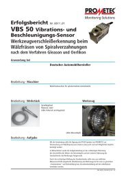
The result<strong>in</strong>g images <strong>of</strong> the camera are presented <strong>in</strong><br />
figure 2.<br />
The camera delivers greyscaled images. In order to<br />
<strong>in</strong>crease the contrast <strong>of</strong> the picture, the images are<br />
presented <strong>in</strong> false color. The color table is given <strong>in</strong><br />
The two presented images are averaged over a full<br />
weld seam and the zone, which is illum<strong>in</strong>ated by the<br />
<strong>laser</strong> beam is highlighted by a circle <strong>in</strong> the image.<br />
They show the <strong>in</strong>teraction zone between the <strong>laser</strong><br />
beam and the workpiece. The images show the<br />
temperature radiation <strong>of</strong> the melt pool and the<br />
keyhole. Differences <strong>in</strong> the <strong>in</strong>tensity will be<br />
<strong>in</strong>terpreted as differences <strong>in</strong> temperature.
f=200mm<br />
Laser beam<br />
Laser beam<br />
f=100mm<br />
1 mm<br />
1 mm<br />
Diameter <strong>of</strong> <strong>laser</strong> beam: 0,4 mm<br />
Parameters: Nd:YAG-Laser; P L : 3,5 kW; v S : 20 m/m<strong>in</strong>;<br />
Diameter <strong>of</strong> <strong>laser</strong> beam: 0,2 mm<br />
Color table:<br />
≅ 100<br />
≅ 150<br />
≅ 200<br />
≅ 255<br />
figure 2<br />
Dimensions <strong>of</strong> the images <strong>of</strong> the camera system at different focal length, f<br />
The resolution <strong>of</strong> the image is controlled by the lens <strong>of</strong><br />
the focus<strong>in</strong>g head <strong>of</strong> the <strong>laser</strong> beam and by the imag<strong>in</strong>g<br />
optic <strong>of</strong> the camera. The change <strong>of</strong> the focal length <strong>of</strong><br />
the focus<strong>in</strong>g head from f=200 mm to f=100 mm causes<br />
an <strong>in</strong>crease <strong>of</strong> the image resolution by a factor <strong>of</strong> two.<br />
There<strong>for</strong>e the number <strong>of</strong> pixels, which are illum<strong>in</strong>ated<br />
by the <strong>in</strong>teraction zone, are nearly the same. In both<br />
cases the width <strong>of</strong> the weld was imaged on 40 pixels <strong>of</strong><br />
the CCD- chip <strong>of</strong> the camera. Each pixel had an image<br />
area <strong>of</strong> 6.7 x 6.7 µm.<br />
The image with a focal length f=200 mm shows a spot<br />
with higher <strong>in</strong>tensity beh<strong>in</strong>d the keyhole region. This<br />
spot is <strong>in</strong>terpreted as the result <strong>of</strong> the melt flow from<br />
figure 3 with the weld<strong>in</strong>g speed <strong>of</strong> 8 m/m<strong>in</strong>. The<br />
image shows a circular <strong>in</strong>tensity distribution and<br />
complies to the region around the keyhole. The<br />
temperature <strong>of</strong> the melt beh<strong>in</strong>d the keyhole seemed to<br />
be too low <strong>for</strong> the camera. At 15 m/m<strong>in</strong>, the velocity <strong>of</strong><br />
the melt flow <strong>in</strong>creases and hot material appears from<br />
the deeper regions <strong>of</strong> the keyhole to the surface. The<br />
<strong>in</strong>tensity distribution <strong>in</strong>creases and acquires a<br />
cyl<strong>in</strong>drical shape. A comparison <strong>of</strong> the images between<br />
8 m/m<strong>in</strong> and 15 m/m<strong>in</strong> shows, that the temperature at<br />
the deeper regions <strong>of</strong> the keyhole. In analogy to a stern<br />
wave <strong>of</strong> a motorboat the <strong>process</strong> generated a stationary<br />
wave <strong>in</strong> the melt pool beh<strong>in</strong>d the keyhole. This effect<br />
is <strong>of</strong>ten shown <strong>in</strong> the follow<strong>in</strong>g chapters.<br />
focal length f=200mm<br />
In the experiments, the weld<strong>in</strong>g speed was <strong>in</strong>creased<br />
up to the threshold <strong>of</strong> hump<strong>in</strong>g. The temperature<br />
distribution <strong>in</strong> the keyhole and <strong>in</strong> the melt pool was<br />
recorded by the camera. The result<strong>in</strong>g images are<br />
presented<br />
<strong>in</strong><br />
the front <strong>of</strong> the keyhole was shifted to the back and the<br />
<strong>in</strong>tensity gradient at the front <strong>in</strong>creases <strong>for</strong> 15 m/m<strong>in</strong>.
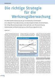
8m/m<strong>in</strong> 15 m/m<strong>in</strong> 20 m/m<strong>in</strong> 22 m/m<strong>in</strong> 22,3 m/m<strong>in</strong> 22,5 m/m<strong>in</strong> 23 m/m<strong>in</strong><br />
Parameters: Nd:YAG-Laser; P L : 3,5 kW; f= 200 mm<br />
Hump<strong>in</strong>g<br />
figure 3<br />
creation <strong>of</strong> Hump<strong>in</strong>g with a focal length f= 200mm<br />
Additionally, the temperature or the <strong>in</strong>tensity at the<br />
center <strong>of</strong> the keyhole <strong>in</strong>creases. These effects were<br />
observed <strong>in</strong> <strong>for</strong>mer presentations and are theoretically<br />
apprehended [6, 7]. Due to the higher speed <strong>of</strong> the<br />
weld<strong>in</strong>g the <strong>laser</strong> beam has to <strong>in</strong>crease preheat<strong>in</strong>g <strong>of</strong><br />
the weld, if the shape <strong>of</strong> the capillary is to be kept<br />
constant. The <strong>in</strong>crease <strong>of</strong> the temperature <strong>in</strong> the center<br />
shows the <strong>in</strong>crease <strong>of</strong> the evaporation rate <strong>in</strong> the<br />
keyhole, which is necessary to uphold the shape <strong>of</strong> the<br />
keyhole.<br />
If the weld<strong>in</strong>g speed is <strong>in</strong>creased, up to 20 m/m<strong>in</strong>, the<br />
temperature at the center decreases and the hot spot<br />
beh<strong>in</strong>d the keyhole occurs. The whole <strong>in</strong>tensity<br />
distribution acquires a figure eight shape. The hot spot<br />
is <strong>in</strong>terpreted as the result <strong>of</strong> a hot melt flow com<strong>in</strong>g<br />
from hotter and deeper parts <strong>of</strong> the keyhole. The<br />
decrease <strong>of</strong> <strong>in</strong>tensity <strong>in</strong> the center <strong>of</strong> the keyhole<br />
<strong>in</strong>dicates a flatter absorption front and a change <strong>in</strong> the<br />
shape <strong>of</strong> the keyhole.<br />
When the speed is <strong>in</strong>creased further, a very sharp<br />
threshold <strong>for</strong> the hump<strong>in</strong>g effect occurs at a speed<br />
between 22,3 m/m<strong>in</strong> and 22,5 m/m<strong>in</strong>. This effect <strong>in</strong> the<br />
melt pool corresponds to a drastic change <strong>in</strong> the images<br />
<strong>of</strong> the camera. The whole <strong>in</strong>tensity distribution <strong>in</strong> the<br />
image decreases. The whole melt pool seemed to<br />
absorb less energy. This is <strong>in</strong>terpreted as an abrupt<br />
change <strong>of</strong> speed <strong>in</strong> the melt flow. Due to the higher<br />
speed <strong>of</strong> the melt flow and the short time <strong>of</strong> direct<br />
contact with the <strong>laser</strong> beam, the melt goes not have the<br />
time to absorb more power from the <strong>laser</strong> and the melt<br />
becomes colder.<br />
The hot spot beh<strong>in</strong>d the keyhole is comparable to the<br />
hot spot at lower weld<strong>in</strong>g speed. The difference is that<br />
the spot is colder and there<strong>for</strong>e the melt freezes quicker<br />
and the melt flow has no time <strong>for</strong> relaxation. This is<br />
the reason <strong>for</strong> the occurrence <strong>of</strong> hump<strong>in</strong>g.<br />
focal length f=100mm<br />
The shape <strong>of</strong> the keyhole and the speed <strong>of</strong> the melt<br />
flow imp<strong>in</strong>ge on the occurrence <strong>of</strong> hump<strong>in</strong>g. The shape<br />
<strong>of</strong> the keyhole and the melt pool are changed us<strong>in</strong>g<br />
different focal length. There<strong>for</strong>e the results <strong>for</strong> a focal<br />
length <strong>of</strong> f=200mm should be compared with another<br />
focal length. Accord<strong>in</strong>g to literature [3-8] it is known,<br />
that the hump<strong>in</strong>g effect can be shifted to higher<br />
weld<strong>in</strong>g speed by the use <strong>of</strong> a smaller focal length.<br />
There<strong>for</strong>e, a focal length <strong>of</strong> f=100mm was used <strong>for</strong> the<br />
comparison.<br />
The result<strong>in</strong>g images are presented <strong>in</strong> figure 4.
10 m/m<strong>in</strong> 15 m/m<strong>in</strong> 20 m/m<strong>in</strong> 25 m/m<strong>in</strong> 30 m/m<strong>in</strong> 35 m/m<strong>in</strong> 40 m/m<strong>in</strong> 45 m/m<strong>in</strong><br />
Parameters: Nd:YAG-Laser; P L : 3,5 kW; f= 100 mm<br />
figure 4<br />
Dependence <strong>of</strong> the averaged camera image on weld<strong>in</strong>g speed us<strong>in</strong>g a focal length <strong>of</strong> f=100mm<br />
Similar to the results with f=200mm the length <strong>of</strong> the<br />
melt pool <strong>in</strong>creases at higher weld<strong>in</strong>g speed. In<br />
contrast to these results the <strong>in</strong>tensity and there<strong>for</strong>e the<br />
temperature <strong>in</strong> the center <strong>of</strong> the keyhole <strong>in</strong>creases with<br />
higher speed. This result <strong>in</strong>dicates that the shape <strong>of</strong> the<br />
keyhole is comparable over all welds. Nevertheless the<br />
temperature <strong>of</strong> the melt decreases aga<strong>in</strong> at higher<br />
speed. At a speed <strong>of</strong> 25 m/m<strong>in</strong> aga<strong>in</strong> a hot spot occurs.<br />
Even at 30 m/m<strong>in</strong> a second spot occurs. The<br />
occurrence <strong>of</strong> hump<strong>in</strong>g will be discussed <strong>in</strong> detail <strong>in</strong><br />
figure 5 and figure 6.<br />
V s = 25 m/m<strong>in</strong><br />
V s = 30 m/m<strong>in</strong><br />
Camera<br />
image<br />
Detail <strong>of</strong><br />
weld seam<br />
Camera<br />
image<br />
Detail <strong>of</strong><br />
weld seam<br />
1 mm<br />
1 mm<br />
crossection<br />
crossection<br />
0,5 mm<br />
0,5 mm<br />
Parameters: Nd:YAG-Laser; P L : 3,5 kW; f= 100 mm<br />
figure 5<br />
occurrence <strong>of</strong> hump<strong>in</strong>g I
Us<strong>in</strong>g a focal length <strong>of</strong> 100 mm the hump<strong>in</strong>g effect<br />
occurs at a speed <strong>of</strong> 30 m/m<strong>in</strong> <strong>for</strong> the first time. In the<br />
images this effect corresponds with the occurrence <strong>of</strong><br />
a second hot spot at the end <strong>of</strong> the melt pool. This<br />
k<strong>in</strong>d <strong>of</strong> hump<strong>in</strong>g is well known from <strong>for</strong>mer<br />
publications [3-7] and corresponds to a bellied shape<br />
<strong>in</strong> the cross section <strong>of</strong> the weld seam. From now on<br />
this k<strong>in</strong>d <strong>of</strong> hump<strong>in</strong>g is called hump<strong>in</strong>g I.<br />
At 25 m/m<strong>in</strong> the basic approach <strong>of</strong> the bellied shape<br />
is identifiable but the weld seam is flatter and the<br />
re<strong>in</strong><strong>for</strong>cement is not as dist<strong>in</strong>ctive as <strong>in</strong> the case <strong>of</strong><br />
30 m/m<strong>in</strong>.<br />
If the weld<strong>in</strong>g speed <strong>in</strong>creases up to 35 m/m<strong>in</strong><br />
(figure 6) the hump<strong>in</strong>g effect vanishes and the<br />
result<strong>in</strong>g weld seam is smooth aga<strong>in</strong>. The difference<br />
<strong>in</strong> the image <strong>of</strong> the melt pool is obvious. The melt is<br />
cooler and the image shows only one hot spot.<br />
At 40 m/m<strong>in</strong> the hump<strong>in</strong>g effect occurs aga<strong>in</strong> and the<br />
effect shows the now expected behavior <strong>of</strong> a cooler<br />
melt pool. This k<strong>in</strong>d <strong>of</strong> hump<strong>in</strong>g is called from now<br />
on hump<strong>in</strong>g II.<br />
V s = 35 m/m<strong>in</strong><br />
V s = 40 m/m<strong>in</strong><br />
Camera<br />
image<br />
Detail <strong>of</strong><br />
weld seam<br />
Camera<br />
image<br />
Detail <strong>of</strong><br />
weld seam<br />
1 mm<br />
1 mm<br />
crossection<br />
crossection<br />
0,5 mm<br />
0,5 mm<br />
Parameters: Nd:YAG-Laser; P L : 3,5 kW; f= 100 mm<br />
figure 6<br />
occurrence <strong>of</strong> hump<strong>in</strong>g II<br />
Tw<strong>in</strong> spot optic<br />
Another way to change the shape <strong>of</strong> the keyhole and<br />
there<strong>for</strong>e the conditions <strong>of</strong> hump<strong>in</strong>g generation is the<br />
use <strong>of</strong> a tw<strong>in</strong> spot optic.<br />
Under this aim the best results were achieved us<strong>in</strong>g a<br />
tw<strong>in</strong> spot optic with a distance <strong>of</strong> 400µm. The<br />
correspond<strong>in</strong>g images are given <strong>in</strong> figure 8.<br />
Tw<strong>in</strong> spot optics with different distances between the<br />
two <strong>laser</strong> spots were tested with regard to their<br />
<strong>in</strong>fluence on the occurrence <strong>of</strong> hump<strong>in</strong>g and the aim to<br />
suppress the <strong>for</strong>mation <strong>of</strong> hump<strong>in</strong>g.
S<strong>in</strong>gle<br />
Spot<br />
Tw<strong>in</strong>spot<br />
200 µm<br />
Tw<strong>in</strong>spot<br />
300 µm<br />
Tw<strong>in</strong>spot<br />
400 µm<br />
Tw<strong>in</strong>spot<br />
500 µm<br />
10 m/m<strong>in</strong><br />
10 m/m<strong>in</strong><br />
10 m/m<strong>in</strong><br />
10 m/m<strong>in</strong><br />
10 m/m<strong>in</strong><br />
Laser beam<br />
Laser beam<br />
Laser beam<br />
1 mm<br />
Parameters: Nd:YAG-Laser; P L : 3,5 kW; f= 100 mm<br />
figure 7<br />
Influence on keyhole <strong>for</strong>mation us<strong>in</strong>g different distances between the two focal spots <strong>of</strong> tw<strong>in</strong><br />
spot optic (0 to 500 µm)<br />
The weld<strong>in</strong>g results show the hump<strong>in</strong>g effect only at<br />
a weld<strong>in</strong>g speed <strong>of</strong> 42 m/m<strong>in</strong>. The so called hump<strong>in</strong>g<br />
I effect was suppressed by the tw<strong>in</strong> spot optic and the<br />
correspond<strong>in</strong>g images shows aga<strong>in</strong> the effect <strong>of</strong><br />
cool<strong>in</strong>g <strong>for</strong> hump<strong>in</strong>g II at 42 m/m<strong>in</strong>.<br />
The image <strong>for</strong> 20m/m<strong>in</strong> shows a hot bridge between<br />
the two <strong>laser</strong> spots. With <strong>in</strong>creas<strong>in</strong>g speed this<br />
develops to a hot spot beh<strong>in</strong>d the first keyhole. But<br />
this spot is <strong>in</strong>fluenced by the keyhole <strong>of</strong> the second<br />
<strong>laser</strong> spot. This may be the reason <strong>for</strong> suppress<strong>in</strong>g the<br />
hump<strong>in</strong>g I effect.
20 m/m<strong>in</strong> 25 m/m<strong>in</strong> 30 m/m<strong>in</strong> 35 m/m<strong>in</strong> 40 m/m<strong>in</strong> 42 m/m<strong>in</strong><br />
Parameters: Nd:YAG-Laser; P L : 3,5 kW; f= 100 mm<br />
Hump<strong>in</strong>g II<br />
figure 8 occurrence <strong>of</strong> hump<strong>in</strong>g us<strong>in</strong>g a tw<strong>in</strong> spot optic with a spot distance <strong>of</strong> 400 µm<br />
Conclusion<br />
The hump<strong>in</strong>g effect can be suppressed with the use <strong>of</strong><br />
a tw<strong>in</strong> spot optic. A detailed description <strong>of</strong> these<br />
results will be given <strong>in</strong> the near future [7]. The<br />
occurrence <strong>of</strong> hump<strong>in</strong>g can be observed <strong>in</strong>-<strong>process</strong><br />
us<strong>in</strong>g a camera positioned coaxial to the <strong>laser</strong> beam.<br />
Due to the hot spots beh<strong>in</strong>d the keyhole, the presence<br />
and the absence <strong>of</strong> hump<strong>in</strong>g can be monitored<br />
def<strong>in</strong>itely.<br />
With these results it is planned to build up a closed<br />
loop <strong>for</strong> the weld<strong>in</strong>g speed to prevent the weld<strong>in</strong>g<br />
<strong>process</strong> <strong>for</strong> hump<strong>in</strong>g effects.<br />
In addition to that the images can be used <strong>in</strong> scientific<br />
work to understand the melt flow dur<strong>in</strong>g weld<strong>in</strong>g.<br />
The <strong>in</strong>terpretation <strong>of</strong> the <strong>in</strong>tensity spots beh<strong>in</strong>d the<br />
keyhole as the result <strong>of</strong> a hot wave must be<br />
<strong>in</strong>vestigated further and verified.<br />
References<br />
[1] Beersiek, J. (2002) New Aspects <strong>of</strong><br />
Monitor<strong>in</strong>g with a CMOS camera <strong>for</strong> Laser<br />
Materials Process<strong>in</strong>g<br />
ICALEO 2002<br />
[2] Beersiek J. (2001) A CMOS camera as a<br />
tool <strong>for</strong> <strong>process</strong> analysis not only <strong>for</strong> <strong>laser</strong><br />
beam weld<strong>in</strong>g<br />
ICALEO 2001, Section F206<br />
[3] Bradstreet, B. (July 1968) Effect <strong>of</strong><br />
Surface Tension and Metal Flow on Weld<br />
Bead Formation<br />
Weld<strong>in</strong>g Research Supplement
[4] Mendez, P. F; Eagar, T. W (October 2003)<br />
Penetration and Defect Formation <strong>in</strong> High-<br />
Current Arc Weld<strong>in</strong>g<br />
Weld<strong>in</strong>g Journal<br />
[5] Beck, M; et al. (1990) Aspects <strong>of</strong><br />
Keyhole/Melt Interaction <strong>in</strong> High Speed<br />
Laser Weld<strong>in</strong>g<br />
Proc. 8 th Int. Symp. On Gas Flow and<br />
Chemical Lasers (GCL), Madrid<br />
[6] Schmidt, H. (1994) Hochgeschw<strong>in</strong>digkeits-<br />
Schweißen von Fe<strong>in</strong>stblechen mit CO 2 -<br />
Laserstrahlung unter besonderer Berücksichtigung<br />
des Hump<strong>in</strong>g-Effektes<br />
Diss. RWTH Aachen,<br />
Wissenschaftsverlag Ma<strong>in</strong>z, Aachen<br />
[7] Pirch, N; et al. (1992) Die Hump<strong>in</strong>g<br />
Instabilität beim Schweißen mit Laserstrahlung<br />
Proc. Konf. Laser ´91, München<br />
[8] Behler, K. to be published