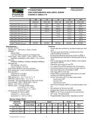
V54C3128(16/80/40)4VC 128Mbit SDRAM 3.3 VOLT, TSOP II / BGA ...
V54C3128(16/80/40)4VC 128Mbit SDRAM 3.3 VOLT, TSOP II / BGA ...
V54C3128(16/80/40)4VC 128Mbit SDRAM 3.3 VOLT, TSOP II / BGA ...

Create successful ePaper yourself
Turn your PDF publications into a flip-book with our unique Google optimized e-Paper software.
ProMOS TECHNOLOGIES<br />
Power On and Initialization<br />
The default power on state of the mode register is<br />
supplier specific and may be undefined. The<br />
following power on and initialization sequence<br />
guarantees the device is preconditioned to each<br />
users specific needs. Like a conventional DRAM,<br />
the Synchronous DRAM must be powered up and<br />
initialized in a predefined manner. During power on,<br />
all VCC and VCCQ pins must be built up<br />
simultaneously to the specified voltage when the<br />
input signals are held in the “NOP” state. The power<br />
on voltage must not exceed VCC+0.3V on any of<br />
the input pins or VCC supplies. The CLK signal<br />
must be started at the same time. After power on,<br />
an initial pause of 200 µs is required followed by a<br />
precharge of both banks using the precharge<br />
command. To prevent data contention on the I/O<br />
bus during power on, it is required that the DQM and<br />
CKE pins be held high during the initial pause<br />
period. Once all banks have been precharged, the<br />
Mode Register Set Command must be issued to<br />
initialize the Mode Register. A minimum of eight<br />
Auto Refresh cycles (CBR) are also required.These<br />
may be done before or after programming the Mode<br />
Register. Failure to follow these steps may lead to<br />
unpredictable start-up modes.<br />
Programming the Mode Register<br />
The Mode register designates the operation<br />
mode at the read or write cycle. This register is divided<br />
into 4 fields. A Burst Length Field to set the<br />
length of the burst, an Addressing Selection bit to<br />
program the column access sequence in a burst cycle<br />
(interleaved or sequential), a CAS Latency Field<br />
to set the access time at clock cycle and a Operation<br />
mode field to differentiate between normal operation<br />
(Burst read and burst Write) and a special<br />
Burst Read and Single Write mode. The mode set<br />
operation must be done before any activate command<br />
after the initial power up. Any content of the<br />
mode register can be altered by re-executing the<br />
<strong>V54C3128</strong>(<strong>16</strong>/<strong>80</strong>/<strong>40</strong>)<strong>4VC</strong><br />
mode set command. All banks must be in precharged<br />
state and CKE must be high at least one<br />
clock before the mode set operation. After the mode<br />
register is set, a Standby or NOP command is required.<br />
Low signals of RAS, CAS, and WE at the<br />
positive edge of the clock activate the mode set operation.<br />
Address input data at this timing defines parameters<br />
to be set as shown in the previous table.<br />
Read and Write Operation<br />
When RAS is low and both CAS and WE are high<br />
at the positive edge of the clock, a RAS cycle starts.<br />
According to address data, a word line of the selected<br />
bank is activated and all of sense amplifiers associated<br />
to the wordline are set. A CAS cycle is<br />
triggered by setting RAS high and CAS low at a<br />
clock timing after a necessary delay, t RCD , from the<br />
RAS timing. WE is used to define either a read<br />
(WE = H) or a write (WE = L) at this stage.<br />
<strong>SDRAM</strong> provides a wide variety of fast access<br />
modes. In a single CAS cycle, serial data read or<br />
write operations are allowed at up to a 200MHz data<br />
rate. The numbers of serial data bits are the burst<br />
length programmed at the mode set operation, i.e.,<br />
one of 1, 2, 4, 8 and full page. Column addresses<br />
are segmented by the burst length and serial data<br />
accesses are done within this boundary. The first<br />
column address to be accessed is supplied at the<br />
CAS timing and the subsequent addresses are generated<br />
automatically by the programmed burst<br />
length and its sequence. For example, in a burst<br />
length of 8 with interleave sequence, if the first address<br />
is ‘2’, then the rest of the burst sequence is 3,<br />
0, 1, 6, 7, 4, and 5.<br />
Full page burst operation is only possible using<br />
sequential burst type. Full Page burst operation<br />
does not terminate once the burst length has been<br />
reached. (At the end of the page, it will wrap to the<br />
start address and continue.) In other words, unlike<br />
burst length of 2, 4, and 8, full page burst continues<br />
until it is terminated using another command.<br />
<strong>V54C3128</strong>(<strong>16</strong>/<strong>80</strong>/<strong>40</strong>)<strong>4VC</strong> Rev. 1.3 November 2008<br />
13