V54C3128(16/80/40)4VC 128Mbit SDRAM 3.3 VOLT, TSOP II / BGA ...
V54C3128(16/80/40)4VC 128Mbit SDRAM 3.3 VOLT, TSOP II / BGA ...
V54C3128(16/80/40)4VC 128Mbit SDRAM 3.3 VOLT, TSOP II / BGA ...

Create successful ePaper yourself
Turn your PDF publications into a flip-book with our unique Google optimized e-Paper software.
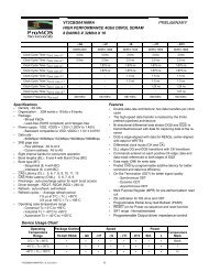
ProMOS TECHNOLOGIES<br />
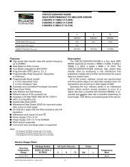
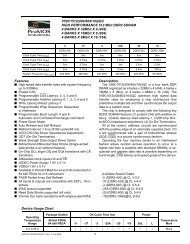
<strong>V54C3128</strong>(<strong>16</strong>/<strong>80</strong>/<strong>40</strong>)<strong>4VC</strong><br />
Recommended Operation and Characteristics for LV-TTL<br />
T A = 0 to 70 °C (Commercial), -<strong>40</strong> to 85°C (Industrial), -<strong>40</strong> to 105°C (Wide), -<strong>40</strong> to 125°C (Extended) ; V SS =<br />
0 V; V CC ,V CCQ = <strong>3.3</strong> V ± 0.3 V<br />
Limit Values<br />
Parameter<br />
Symbol<br />
min.<br />
max.<br />
Unit<br />
Notes<br />
Input high voltage V IH 2.0 Vcc+0.3 V 1, 2<br />
Input low voltage V IL – 0.3 0.8 V 1, 2<br />
Output high voltage (I OUT = – 4.0 mA) V OH 2.4 – V<br />
Output low voltage (I OUT = 4.0 mA) V OL – 0.4 V<br />
Input leakage current, any input<br />
(0 V < V IN < 3.6 V, all other inputs = 0 V)<br />
Output leakage current<br />
(I/O is disabled, 0 V < V OUT < V CC )<br />
I I(L) – 5 5 µA<br />
I O(L) – 5 5 µA<br />
Note:<br />
1. All voltages are referenced to V SS .<br />
2. V IH may overshoot to V CC + 2.0 V for pulse width of < 4ns with <strong>3.3</strong>V. V IL may undershoot to -2.0 V for pulse width < 4.0 ns with<br />
<strong>3.3</strong>V. Pulse width measured at 50% points with amplitude measured peak to DC reference.<br />
Operating Currents (T A = 0 to 70 °C (Commercial), -<strong>40</strong> to 85°C (Industrial) ,-<strong>40</strong> to 105°C (Wide), -<strong>40</strong> to<br />
125°C (Extended), V CC = <strong>3.3</strong>V ± 0.3V)<br />
(Recommended Operating Conditions unless otherwise noted)<br />
Max.<br />
Symbol Parameter & Test Condition<br />
-5 -6 -7 / -7PC -10<br />
Unit<br />
Note<br />
ICC1<br />
Operating Current<br />
t RC = t RCMIN. , t RC = t CKMIN .<br />
Active-precharge command cycling,<br />
without Burst Operation<br />
1 bank operation 145 130 120 110 mA 7<br />
ICC2P Precharge Standby Current<br />
t CK = min. 2 2 2 2 mA 7<br />
ICC2PS<br />
in Power Down Mode<br />
t<br />
CS =V IH , CKE≤ V CK = Infinity 2 2 2 2 mA 7<br />
IL(max)<br />
ICC2N Precharge Standby Current<br />
t CK = min. 25 25 25 25 mA<br />
ICC2NS<br />
in Non-Power Down Mode<br />
t<br />
CS =V IH , CKE≥ V CK = Infinity 15 15 15 15 mA<br />
IL(max)<br />
ICC3N<br />
ICC3P<br />
ICC4<br />
ICC5<br />
ICC6<br />
No Operating Current<br />
t CK = min, CS = V IH(min)<br />
bank ; active state ( 4 banks)<br />
Burst Operating Current<br />
t CK = min<br />
Read/Write command cycling<br />
Auto Refresh Current<br />
t CK = min<br />
Auto Refresh command cycling<br />
Self Refresh Current<br />
Self Refresh Mode, CKE≤ 0.2V<br />
CKE ≥ V IH(MIN.) 45 <strong>40</strong> <strong>40</strong> <strong>40</strong> mA<br />
CKE ≤ V IL(MAX.)<br />
(Power down mode)<br />
5 5 5 5 mA<br />
<strong>16</strong>0 150 1<strong>40</strong> 130 mA 7,8<br />
210 200 190 1<strong>80</strong> mA 7<br />
Standard 2 2 2 2 mA<br />
Low-Power <strong>80</strong>0 <strong>80</strong>0 <strong>80</strong>0 <strong>80</strong>0 uA<br />
Notes:<br />
7. These parameters depend on the cycle rate and these values are measured by the cycle rate under the minimum value of t CK and<br />
<strong>V54C3128</strong>(<strong>16</strong>/<strong>80</strong>/<strong>40</strong>)<strong>4VC</strong> Rev. 1.3 November 2008<br />
17