Unfiltered FQPSK: Another Interpretation and Further Enhancements
Unfiltered FQPSK: Another Interpretation and Further Enhancements
Unfiltered FQPSK: Another Interpretation and Further Enhancements

Create successful ePaper yourself
Turn your PDF publications into a flip-book with our unique Google optimized e-Paper software.
then typical waveforms for the I <strong>and</strong> Q IJF encoder outputs<br />
are illustrated in Figure 2.<br />
An identical modulation to x I (t) (<strong>and</strong> likewise for<br />
x Q (t)) generated from the combination of (1) <strong>and</strong> (2) can<br />
be obtained directly from the binary data sequence {d In }<br />
itself, without the need for defining a 4-ary mapping<br />
based on the transition properties of the sequence. In<br />
particular, if we define the two-symbol wide raised<br />
cosine pulse shape<br />
pt ( ) = sin<br />
then the I modulation<br />
x () t = ∑ d p( t−<br />
nT)<br />
I<br />
will be identical to that generated by the above IJF<br />
scheme. Similarly,<br />
⎛ ⎞<br />
x () t = d p( t n T)<br />
Q ∑ − +<br />
Qn<br />
s<br />
n=−∞<br />
⎝ 2⎠<br />
∞ 1<br />
(a)<br />
(c)<br />
∞<br />
n=−∞<br />
( )<br />
⎛ π t+<br />
T /<br />
⎜<br />
⎝ 2T<br />
2 s 2<br />
In<br />
s<br />
⎞<br />
⎟, −Ts<br />
/ 2≤ t ≤3Ts<br />
/ 2<br />
⎠<br />
s<br />
(b)<br />
(d)<br />
(3)<br />
(4)<br />
(5)<br />
would also be identical to that generated by the above<br />
IJF scheme. A quadrature modulation scheme formed<br />
from x I (t) of (4) <strong>and</strong> x Q (t) of (5) is precisely what Austin<br />
<strong>and</strong> Chang [7] referred to as SQORC modulation, namely,<br />
independent I <strong>and</strong> Q modulations with overlapping<br />
raised cosine pulses on each channel. The resulting carrier<br />
modulated waveform is described by<br />
xt () = x1()cos t ωct+<br />
xQ()sin<br />
t ωct<br />
Symbol-by-symbol cross correlator mapping for <strong>FQPSK</strong><br />
Before revealing the modification of <strong>FQPSK</strong>, which<br />
results in a transmitted signal having a continuous first<br />
derivative, we first recast the original characterization<br />
of <strong>FQPSK</strong> in terms of a cross correlation operation performed<br />
on the pair of IJF encoder outputs every half<br />
symbol interval into a mapping performed directly on<br />
the input I <strong>and</strong> Q data sequences every full symbol interval.<br />
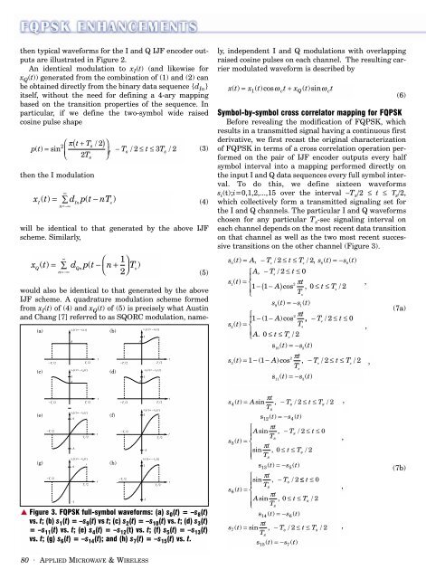
To do this, we define sixteen waveforms<br />
s i (t);i=0,1,2,...,15 over the interval –T s /2 ≤ t ≤ Τ s /2,<br />
which collectively form a transmitted signaling set for<br />
the I <strong>and</strong> Q channels. The particular I <strong>and</strong> Q waveforms<br />
chosen for any particular T s -sec signaling interval on<br />
each channel depends on the most recent data transition<br />
on that channel as well as the two most recent successive<br />
transitions on the other channel (Figure 3).<br />
s () t = A, −T /<br />
s<br />
2≤ t ≤ T /<br />
s<br />
2, s () t = −s () t<br />
0 8 0<br />
⎧A, −T / 2≤ s<br />
t ≤0<br />
⎪<br />
s()<br />
1<br />
t = ⎨<br />
2 πt<br />
,<br />
⎪<br />
1−( 1−<br />
A) cos , 0≤ t ≤T<br />
/ 2<br />
s<br />
⎩<br />
Ts<br />
s ()<br />
9<br />
t =−s()<br />
1<br />
t<br />
⎧<br />
2 π t<br />
⎪1−( 1−<br />
A)cos<br />
, −Ts<br />
/ 2≤ t ≤0<br />
s () t =<br />
T<br />
2 ⎨<br />
s<br />
,<br />
⎪<br />
⎩A. 0≤<br />
t ≤Ts<br />
/ 2<br />
s10() t =−s2()<br />
t<br />
2 πt<br />
s ( t) = −( − A)cos , −Ts<br />
/ ≤ t ≤Ts<br />
/<br />
3<br />
1 1 2 2 ,<br />
Ts<br />
s () t =−s () t<br />
11<br />
3<br />
(6)<br />
(7a)<br />
(e)<br />
(g)<br />
(f)<br />
(h)<br />
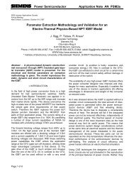
▲ Figure 3. <strong>FQPSK</strong> full-symbol waveforms: (a) s 0 (t) = –s 8 (t)<br />
vs. t; (b) s 1 (t) = –s 9 (t) vs t; (c) s 2 (t) = –s 10 (t) vs. t; (d) s 3 (t)<br />
= –s 11 (t) vs. t; (e) s 4 (t) = –s 12 (t) vs. t; (f) s 5 (t) = –s 13 (t)<br />
vs. t; (g) s 6 (t) = –s 14 (t); <strong>and</strong> (h) s 7 (t) = –s 15 (t) vs. t.<br />
πt<br />
s4( t) = Asin , −Ts<br />
/ 2≤ t ≤Ts<br />
/ 2<br />
T<br />
s<br />
12<br />
s<br />
() t =−s () t<br />
⎧ πt<br />
Asin , −Ts<br />
/ 2≤ t ≤0<br />
⎪ Ts<br />
s5()<br />
t = ⎨<br />
⎪ πt<br />
sin , 0≤<br />
t ≤Ts<br />
/ 2<br />
⎩⎪<br />
Ts<br />
s () t =−s () t<br />
13<br />
⎧ πt<br />
sin , − Ts<br />
/ 2 ≤ t ≤0<br />
⎪ Ts<br />
s6()<br />
t = ⎨<br />
⎪ πt<br />
Asin , 0 ≤ t ≤Ts<br />
/ 2<br />
⎩⎪<br />
Ts<br />
s () t =−s () t<br />
πt<br />
s7<br />
( t) = sin , −Ts<br />
/ 2≤ t ≤Ts<br />
/ 2<br />
T<br />
s<br />
14<br />
15<br />
s<br />
5<br />
6<br />
4<br />
() t =−s () t<br />
7<br />
,<br />
,<br />
,<br />
,<br />
(7b)<br />
80 · APPLIED MICROWAVE & WIRELESS