Unfiltered FQPSK: Another Interpretation and Further Enhancements
Unfiltered FQPSK: Another Interpretation and Further Enhancements
Unfiltered FQPSK: Another Interpretation and Further Enhancements

You also want an ePaper? Increase the reach of your titles
YUMPU automatically turns print PDFs into web optimized ePapers that Google loves.
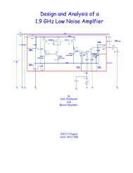
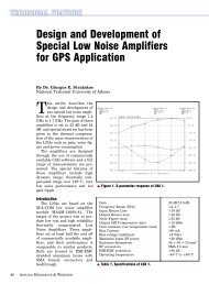
▲ Figure 5. Original <strong>and</strong> new <strong>FQPSK</strong> shapes.<br />
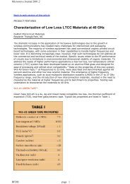
▲ Figure 6. Power spectra of conventional <strong>and</strong> enhanced <strong>FQPSK</strong>: (a)<br />
without SSPA; <strong>and</strong> (b) with SSPA.<br />
s<br />
4<br />
⎧ πt<br />
2 πt<br />
sin + ( 1− A)sin , −Ts<br />
/ 2≤ t ≤0<br />
⎪ Ts<br />
Ts<br />
() t = ⎨<br />
,<br />
⎪ πt<br />
2 πt<br />
sin −( 1− A)sin , 0 ≤ t ≤Ts<br />
/ 2<br />
⎩⎪<br />
Ts<br />
Ts<br />
() t =−s () t<br />
s 12<br />
4<br />
(10)<br />
This minor change, which produces a complete symmetry<br />
in the waveform set, has an advantage from the<br />
st<strong>and</strong>point of hardware implementation <strong>and</strong> produces a<br />
negligible change in spectral properties of the transmitted<br />
waveform. Nevertheless, for the remainder of the<br />
discussion, we shall ignore this minor change <strong>and</strong><br />
assume the version of enhanced <strong>FQPSK</strong> first introduced<br />
in this section.<br />
<strong>Interpretation</strong> of <strong>FQPSK</strong> as a trellis-coded modulation<br />
The I <strong>and</strong> Q mappings given in Tables 1 <strong>and</strong> 2 are<br />
alternately described in terms of the (0,1) representation<br />
of the I <strong>and</strong> Q data symbols <strong>and</strong> their transitions.<br />
Specifically, define<br />
D In = ∆ (1–d In )/2, D Qn = ∆ (1−d Qn )/2 (11)<br />
which both range on the set (0,1). Then, defining the<br />
BCD representation of the indices i <strong>and</strong> j by<br />
with<br />
3<br />
i= I3<br />
× 2 + I2<br />
× 2 + I1<br />
× 2 + I0<br />
× 2<br />
3<br />
2<br />
1<br />
j= Q × 2 + Q × 2 + Q × 2 + Q × 2<br />
3<br />
I = DQn ⊕ D Q D D<br />
0 Q n− , =<br />
I n<br />
⊕<br />
, 1 0 , + 1 In<br />
I = DQn , −<br />
⊕ DQn , −<br />
, Q = DIn⊕ DIn<br />
, −<br />
= I<br />
I =<br />
2<br />
D ⊕<br />
In<br />
D ,<br />
I n 1<br />
Q =<br />
2<br />
D ⊕<br />
Qn<br />
D =<br />
, −<br />
Q,<br />
n−1 I0<br />
I = D , Q = D<br />
1 1 2 1 1 2<br />
3 In 3<br />
2<br />
2<br />
Qn<br />
1<br />
(12)<br />
(13)<br />
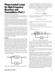
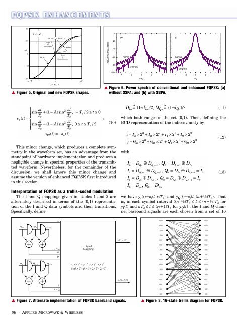
we have y I (t)=s i (t–nT s ) <strong>and</strong> y Q (t)=s j (t–(n+½)T s ). That<br />
is, in each symbol interval ((n–½)T s ≤ t ≤ (n+½)T s for<br />
y I (t) <strong>and</strong> nT s ≤ t ≤ (n+1)T s for y Q (t)), the I <strong>and</strong> Q channel<br />
baseb<strong>and</strong> signals are each chosen from a set of 16<br />
1<br />
0<br />
0<br />
0<br />
▲ Figure 7. Alternate implementation of <strong>FQPSK</strong> baseb<strong>and</strong> signals.<br />
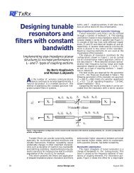
▲ Figure 8. 16-state trellis diagram for <strong>FQPSK</strong>.<br />
86 · APPLIED MICROWAVE & WIRELESS