steppii-55/56-lt - Falcom
steppii-55/56-lt - Falcom
steppii-55/56-lt - Falcom

Create successful ePaper yourself
Turn your PDF publications into a flip-book with our unique Google optimized e-Paper software.
THIS DOCUMENT IS AVAILABLE AT HTTP://WWW.FALCOM.DE/.<br />
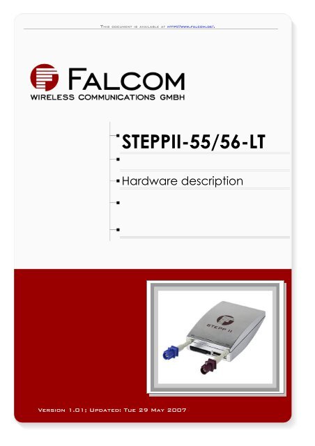
STEPPII-<strong>55</strong>/<strong>56</strong>-LT<br />
Hardware description<br />
Version 1.01; Updated: Tue 29 May 2007
STEPPII-<strong>55</strong>/<strong>56</strong>-LT HARDWARE DESCRIPTION VERSION 1.01<br />
Table of contents<br />
1 INTRODUCTION ........................................................................ 6<br />
1.1 GENERAL ............................................................................................................................... 6<br />
1.2 CIRCUIT CONCEPT .................................................................................................................... 7<br />
1.3 SCOPE OF DELIVERY ................................................................................................................. 8<br />
1.4 USED ABBREVIATIONS ................................................................................................................ 8<br />
1.5 RELATED DOCUMENTS ............................................................................................................... 9<br />
2 SECURITY ............................................................................... 10<br />
2.1 GENERAL INFORMATION ............................................................................................................ 10<br />
2.2 EXPOSURE TO RF ENERGY ....................................................................................................... 10<br />
2.3 EFFICIENT MODEM OPERATION .................................................................................................... 10<br />
2.4 ANTENNA CARE AND REPLACEMENT ............................................................................................. 11<br />
2.5 DRIVING ............................................................................................................................... 11<br />
2.6 ELECTRONIC DEVICES .............................................................................................................. 11<br />
2.7 VEHICLE ELECTRONIC EQUIPMENT ............................................................................................... 11<br />
2.8 MEDICAL ELECTRONIC EQUIPMENT ............................................................................................... 11<br />
2.9 AIRCRAFT ............................................................................................................................. 11<br />
2.10 CHILDREN .......................................................................................................................... 12<br />
2.11 BLASTING AREAS .................................................................................................................. 12<br />
2.12 POTENTIALLY EXPLOSIVE ATMOSPHERES ..................................................................................... 12<br />
2.13 NON-IONIZING RADIATION ........................................................................................................ 12<br />
2.14 BATTERY SAFETY ................................................................................................................. 12<br />
3 SAFETY STANDARDS ............................................................ 14<br />
4 TECHNICAL DATA .................................................................. 15<br />
4.1 GENERAL SPECIFICATIONS OF TERMINAL STEPPII-<strong>55</strong>/<strong>56</strong>-LT ........................................................ 15<br />
4.1.1 Power consumption ....................................................................................................... 16<br />
4.1.2 Operating temperatures ................................................................................................. 16<br />
4.2 BATTERY TECHNICAL DATA ...................................................................................................... 17<br />
4.3 TECHNICAL SPECIFICATIONS OF GSM/GPRS ENGINE* ................................................................... 18<br />
4.3.1 Air interface of the STEPPII-<strong>55</strong>/<strong>56</strong>-LT GSM/GPRS part ............................................... 19<br />
4.4 TECHNICAL SPECIFICATIONS OF GPS RECEIVER ............................................................................. 21<br />
4.5 NMEA DATA MESSAGE ........................................................................................................... 22<br />
5 FUNCTIONAL DESCRIPTION ................................................. 23<br />
5.1 HOW DOES IT WORK ................................................................................................................ 23<br />
5.2 FALCOM STEPPII-<strong>55</strong>/<strong>56</strong>-LT TYPICAL APPLICATIONS ............................................................... 24<br />
6 STEPPII-<strong>55</strong>/<strong>56</strong>-LT APPLICATION INTERFACE ..................... 27<br />
6.1 POWER SUPPLY ..................................................................................................................... 27<br />
6.1.1 Power up/down scenarios .............................................................................................. 27<br />
6.1.2 Power supply pins (14, 15 and 16) on the 16-pin connector .......................................... 27<br />
6.1.3 Automatic shutdown ...................................................................................................... 27<br />
6.1.3.1 Over vo<strong>lt</strong>age shutdown ................................................................................................................ 28<br />
6.1.4 Charging & Discharging process of the battery ............................................................. 28<br />
6.2 AUTOMATIC GPRS MULTISLOT CLASS CHANGE ............................................................................ 28<br />
6.3 DETERMINING THE EXTERNAL EQUIPMENT TYPE ............................................................................ 28<br />
7 HARDWARE INTERFACES .................................................... 30<br />
This confidential document is a property of FALCOM and may not be copied or circulated without previous permission.<br />
Page 2
STEPPII-<strong>55</strong>/<strong>56</strong>-LT HARDWARE DESCRIPTION VERSION 1.01<br />
7.1 INTERFACE A (16-PIN MOLEX 43045-1609) .............................................................................. 31<br />
7.1.1 Description of the 16-pin connector ............................................................................... 31<br />
7.1.2 Special pin description ................................................................................................... 32<br />
7.1.2.1 Analog inputs (pin 2, 4) ................................................................................................................ 32<br />
7.1.2.2 Inputs (pin 6, 8, 10, 12) ................................................................................................................ 33<br />
7.1.2.3 Outputs (pin 5, 7, 9, 11) .............................................................................................................. 34<br />
7.1.2.4 BATT ON/OFF (pin 14) ................................................................................................................ 34<br />
7.1.2.5 Ignition (pin 13) ............................................................................................................................ 35<br />
7.2 INTERFACE B (SIM CARD INTERFACE MOLEX-91228-0002) .......................................................... 36<br />
7.3 INTERFACES C AND D ............................................................................................................. 36<br />
7.4 INTERFACE E (AMP <strong>55</strong>8<strong>55</strong>6-1 CONNECTOR) ............................................................................ 37<br />
7.4.1 The 15- pin connector description ................................................................................. 37<br />
7.4.2 Special pin description ................................................................................................... 38<br />
7.4.2.1 VC 5 ............................................................................................................................................. 38<br />
7.4.2.2 Boot select ................................................................................................................................... 38<br />
7.4.2.3 Serial communication signals (RxA, TxA) .................................................................................... 38<br />
7.4.2.4 Speaker outputs characteristics ................................................................................................... 39<br />
7.5 INTERFACE F (LED’S DESCRIPTION) ........................................................................................... 39<br />
7.6 INTERFACE E (MOUNTING HOLES) .............................................................................................. 40<br />
7.6.1.1 Mounting the cradle to the terminal .............................................................................................. 40<br />
7.6.1.2 Placing the terminal ......................................................................................................................41<br />
8 HOUSING ................................................................................. 42<br />
9 STEPPII-<strong>55</strong>/<strong>56</strong>-LT-MOUNTING CRADLE ............................... 43<br />
10 RF EXPOSURES ................................................................... 44<br />
11 APPENDIX ............................................................................. 45<br />
11.1 SCHEMATICS ....................................................................................................................... 45<br />
11.1.1 Installation guidance for 16-pin Molex connector ......................................................... 45<br />
11.1.2 Installation guidance for 15-pin AMP connector .......................................................... 46<br />
This confidential document is a property of FALCOM and may not be copied or circulated without previous permission.<br />
Page 3
STEPPII-<strong>55</strong>/<strong>56</strong>-LT HARDWARE DESCRIPTION VERSION 1.01<br />
Version history:<br />
Version<br />
number<br />
Author Changes Change date<br />
1.00 F. Beqiri Initial release 23/02/2007<br />
1.01 F. Beqiri<br />
The operating vo<strong>lt</strong>age (VVC+ and GND) is protected from reverse pole<br />
connection as long no grounded antenna and/or an AMP connector is NOT<br />
connected to the STEPPII (see chapter 6.1).<br />
29/05/2007<br />
This confidential document is a property of FALCOM and may not be copied or circulated without previous permission.<br />
Page 4
STEPPII-<strong>55</strong>/<strong>56</strong>-LT HARDWARE DESCRIPTION VERSION 1.01<br />
Cautions<br />
Information furnished herein by FALCOM is accurate and reliable. However, no<br />
responsibility is assumed for its use.<br />
Please, read carefully the safety precautions.<br />
If you have any technical questions regarding this document or the product<br />
described in it, please contact your vendor.<br />
General information about FALCOM and its range of products are available at the<br />
following Internet address: http://www.falcom.de/<br />
Trademarks<br />
Some mentioned products are registered trademarks of their respective companies.<br />
Copyright<br />
This documentation is copyrighted by FALCOM WIRELESS COMMUNICATIONS GmbH with all<br />
rights reserved. No part of this documentation may be produced in any form without<br />
the prior written permission of FALCOM WIRELESS COMMUNICATIONS GmbH.<br />
FALCOM Wireless Communications GmbH.<br />
No patent liability is assumed with respect to the use of the information contained<br />
herein.<br />
This confidential document is a property of FALCOM and may not be copied or circulated without previous permission.<br />
Page 5
STEPPII-<strong>55</strong>/<strong>56</strong>-LT HARDWARE DESCRIPTION VERSION 1.01<br />
1 INTRODUCTION<br />
This product manual is only addressed to qualified personnel which is well skilled in<br />
electronical/electrical installation and not addressed to private consumers/end<br />
users. The installation, implementing or setting into operation of the product can only<br />
be performed by this qualified personnel.<br />
1.1 General<br />
This description is focused on the GSM/GPRS and GPS terminal STEPPII-<strong>55</strong>/<strong>56</strong>-LT from<br />
FALCOM GmbH. It contains information about purpose and use of the STEPPII-<strong>55</strong>/<strong>56</strong>-<br />
LT concept.<br />
In order quickly to start and immediately and comprehensive to use all functions and<br />
to avoid any mistakes of STEPPII-<strong>55</strong>/<strong>56</strong>-LT terminal on your utilization, we recommend<br />
to read the following references and suggestions for using your new STEPPII-<strong>55</strong>/<strong>56</strong>-LT<br />
terminal.<br />
The STEPPII-<strong>55</strong>/<strong>56</strong>-LT is a Plug-and-Play device, which provides powerful state-of-the<br />
art technologies (GSM, GPS, internet) and makes them available for quick and easy<br />
integration into a number of applications for the vertical and horizontal market. The<br />
new STEPPII-<strong>55</strong>/<strong>56</strong>-LT concept is a Full Type Approved combined GSM/GPRS/GPS<br />
Smart Terminal.<br />
The compact design of the GSM/GPRS/GSM STEPPII-<strong>55</strong>/<strong>56</strong>-LT terminal integrates it in<br />
an all-in-one solution. This combination concept and internally embedded software<br />
(known as firmware) make it available to be used in a wild range of tracking<br />
solutions such as fleet management, vehicle tracking, navigation, emergency<br />
calling, location-based services and many others.<br />
The STEPPII-<strong>55</strong>/<strong>56</strong>-LT is designed for use on any GSM850, GSM1800 and GSM1900<br />
network. This single compact device is Tri-band GSM/GPRS engine that works on the<br />
three frequencies GSM 850MHz, GSM 1800 MHz and GSM 1900 MHz, it supports also<br />
state-of-art GPS technology for satellite navigation.<br />
The embedded firmware based on the eCos operating system for the TCP/IP<br />
communication protocol (TCP/IP stack) converts data streams into data packets<br />
and makes GPRS traffic possible for industrial and automotive applications. No PDA<br />
or laptop is needed for establishing a GPRS connection. It has its own TCP/IP and PPP<br />
stack and will work as a stand-alone terminal. STEPPII-<strong>55</strong>/<strong>56</strong>-LT features GPRS Mu<strong>lt</strong>islot<br />
class 10 and supports the GPRS coding schemes CS-1, CS-2, CS-3 and CS-4. The<br />
STEPPII-<strong>55</strong>/<strong>56</strong>-LT terminal can send and receive data by GSM and GPRS networks. It<br />
supports SMS, data and voice calls as well as Internet and e-mail. The STEPPII-<strong>55</strong>/<strong>56</strong>-LT<br />
terminal can be easily controlled by using SMS and PRSF commands provided on the<br />
embedded software for all kinds of operations.<br />
The internal advanced GPS system uses twelve parallel channels, providing highly<br />
accurate positional, speed, time and date information. Using satellite signals the<br />
embedded GPS module enables users to determine the position of device<br />
anywhere in the world. The STEPPII-<strong>55</strong>/<strong>56</strong>-LT module has an integrated TCXO that also<br />
improves the GPS system performance. Due to the temperature stabilizing its position<br />
is determined more precisely.<br />
A compact “stacked FLASH/SRAM” device stores the STEPPII-<strong>55</strong>/<strong>56</strong>-LT software in the<br />
FLASH memory section of terminal, and a static RAM section provides the additional<br />
storage capacity required by GPRS connectivity.<br />
The physical interfaces to the terminal application are made through integrated<br />
connectors. These are required for controlling the unit, receiving GPS location data,<br />
transferring data and audio signals and providing power supply lines. STEPPII-<strong>55</strong>/<strong>56</strong>-LT<br />
This confidential document is a property of FALCOM and may not be copied or circulated without previous permission.<br />
Page 6
STEPPII-<strong>55</strong>/<strong>56</strong>-LT HARDWARE DESCRIPTION VERSION 1.01<br />
provides a serial interface (2-wire and GND on the 16-pin AMP connector) giving you<br />
maximum flexibility for local use.<br />
The internal backup Battery (LiIon- 850 mA/h) is available in case of external Power<br />
failure.<br />
Figure 1 shows the front and backside of the STEPPII-<strong>55</strong>/<strong>56</strong>-LT.<br />
a) front side b) back side<br />
Figure 1: Front and back side of STEPPII-<strong>55</strong>/<strong>56</strong>-LT<br />
1.2 Circuit concept<br />
The STEPPII-<strong>55</strong>/<strong>56</strong>-LT architecture includes the following major functional components<br />
(see figure 2):<br />
� Architecture integrates:<br />
� high-performance Tri Band GSM/GPRS core<br />
� 12 parallel channel low-power GPS core<br />
� ARM7TDMI processor that controls all functions of the system<br />
� Power Control circuitry with 850 mAh Li-Ion, backup battery<br />
� Audio amplifier<br />
� Interface circuitry<br />
� Physical interfaces:<br />
� 16-pin Molex connector (Type: Molex 43045-1609, and counterpart:<br />
Casing: 43025-1600 and Box type spring contact: 43031-0001) for power<br />
supply and I/O’s<br />
� 15-pin AMP connector (Type: AMP5-<strong>55</strong>8<strong>55</strong>6-1, and counterpart: <strong>55</strong>8666-<br />
1) for audio interfaces and software update<br />
� SIM Card reader (Type: Molex-91228-0002 small SIM Card)<br />
� GSM antenna interface (Type: Connector 50 Ω Fakra/Radiall SMB-male)<br />
� GPS antenna interface (Type: Connector 50 Ω Fakra/Radiall SMB-male)<br />
This confidential document is a property of FALCOM and may not be copied or circulated without previous permission.<br />
Page 7
STEPPII-<strong>55</strong>/<strong>56</strong>-LT HARDWARE DESCRIPTION VERSION 1.01<br />
Figure 2: Architecture of the STEPPII-<strong>55</strong>/<strong>56</strong>-LT terminal<br />
1.3 Scope of delivery<br />
Check the contents of the package. In case of damaged or missing any item,<br />
please contact your dealer immediately.<br />
Concerning the STEPPII-LT, there are four different terminals, which operate in the<br />
different frequencies:<br />
� STEPPII-<strong>55</strong>-LT is a Tri-band device, which operates in the three<br />
frequencies GSM 900 MHz, DCS 1800 MHz and PCS 1900 MHz, and is<br />
available to use in the European and Asian Networks.<br />
� STEPPII-<strong>56</strong>-LT is a Tri-band device, which operates in the three<br />
frequencies GSM 850 MHz, DCS 1800 MHz and PCS 1900 MHz, and is<br />
available to use in the American Networks.<br />
Regarding the electrical interfaces, mechanical specification (dimension, form etc.)<br />
and electrical specification are the same to all terminals.<br />
Please, note that according to your requirements you can choose the desired<br />
STEPPII-LT device.<br />
1.4 Used abbreviations<br />
Abbreviation Description<br />
ASIC Application Specific Integrated Circuit<br />
DOP Dilution of Precision<br />
GPS Global Positioning System<br />
GSM Global Standard for Mobile Communications<br />
GGA GPS Fixed Data<br />
HDOP Horizontal DOP<br />
HW Hardware<br />
IMEI International Mobile Equipment Identity<br />
I/O Input/Output<br />
NMEA National Marine Electronics Association<br />
PRN Pseudorandom Noise Number – The Identity of GPS satellites<br />
This confidential document is a property of FALCOM and may not be copied or circulated without previous permission.<br />
Page 8
STEPPII-<strong>55</strong>/<strong>56</strong>-LT HARDWARE DESCRIPTION VERSION 1.01<br />
RF Radio Frequency<br />
RTC Real Time Clock<br />
RXQUAL Received Signal Quality<br />
SIM Subscriber Identification Module<br />
SMS Short Message Service<br />
SRAM Static Random Access Memory<br />
TA Terminal Adapter<br />
TE Terminal Equipment<br />
TP Transmit Protocol<br />
TTFF Time to First Fix<br />
SA Selective Availability<br />
WAAS Wide Area Augmentation System<br />
MSK Minimum Shift Keying<br />
Table 1: Used abbreviations<br />
1.5 Related documents<br />
1. ETSI GSM 07.05:“Use of Data Terminal Equipment–Data Circuit terminating Equipment<br />
interface for Short Message Service and Cell Broadcast Service”<br />
2. ETSI GSM 07.07“AT command set for GSM Mobile Equipment”<br />
3. ITU-T V.25ter “Serial asynchronous automatic dialing and control”<br />
4. SiRF binary and NMEA protocol specification<br />
5. steppII_getting_started.pdf<br />
6. steppII_firmware_2.3.xx_manual.pdf (supporting GSM & GPRS services)<br />
7. steppII_firmware_1.6.xx_manual.pdf (supporting GSM services, only)<br />
8. falcom_eCos_SDK_user_guide.pdf<br />
9. Application_notes_on_vehicle_mounting.pdf<br />
10. AppNotes_connecting_a_bar_code_scanner_to a_STEPPII.pdf<br />
This confidential document is a property of FALCOM and may not be copied or circulated without previous permission.<br />
Page 9
STEPPII-<strong>55</strong>/<strong>56</strong>-LT HARDWARE DESCRIPTION VERSION 1.01<br />
2 SECURITY<br />
IMPORTANT FOR THE EFFICIENT AND SAFE OPERATION OF YOUR GSM-MODEM, READ<br />
THIS INFORMATION BEFORE USE!<br />
Your cellular engine STEPPII-<strong>55</strong>/<strong>56</strong>-LT is one of the most exciting and innovative<br />
electronic products ever developed. With it you can stay in contact with your office,<br />
your home, emergency services and others, wherever service is provided.<br />
This chapter contains important information for the safe and reliable use of the<br />
STEPPII-<strong>55</strong>/<strong>56</strong>-LT. Please read this chapter carefully before starting to use the cellular<br />
engine STEPPII-<strong>55</strong>/<strong>56</strong>-LT.<br />
2.1 General information<br />
Your STEPPII-<strong>55</strong>/<strong>56</strong>-LT device utilizes the GSM/GPRS/GPS standard for cellular<br />
technology. GSM/GPRS is a newer radio frequency („RF“) technology than the<br />
current FM technology that has been used for radio communications for decades.<br />
The GSM standard has been established for use in the European community and<br />
elsewhere. Your modem is actually a low power radio transmitter and receiver. It<br />
sends out and receives radio frequency energy. When you use your modem, the<br />
cellular system handling your calls controls both the radio frequency and the power<br />
level of your cellular modem.<br />
For the use of the acquired devices SIM cards are needed, which are not included in<br />
the scope of delivery of the device. The SIM cards can be acquired e.g. by specific<br />
providers. From the use of the SIM cards can resu<strong>lt</strong> additional costs, which are to be<br />
borne by the purchaser (client) of the devices. The seller does not cover the extra<br />
costs for the use of the devices. The seller gives no recommendation for the use of<br />
specific SIM cards and does not liable also for the fact that the devices are usable<br />
with all available SIM cards. The seller also covers no other costs, that are needed for<br />
the application of the customer in connection with this device.<br />
2.2 Exposure to RF energy<br />
There has been some public concern about possible hea<strong>lt</strong>h effects of using a GSM<br />
modem. A<strong>lt</strong>hough research on hea<strong>lt</strong>h effects from RF energy has focused for many<br />
years on the current RF technology, scientists have begun research regarding newer<br />
radio technologies, such as GSM. After existing research had been reviewed, and<br />
after compliance to all applicable safety standards had been tested, it has been<br />
concluded that the product is fit for use.<br />
If you are concerned about exposure to RF energy there are things you can do to<br />
minimize exposure. Obviously, limiting the duration of your calls will reduce your<br />
exposure to RF energy. In addition, you can reduce RF exposure by operating your<br />
cellular modem efficiently by following the guidelines below.<br />
2.3 Efficient modem operation<br />
In order to operate your modem at the lowest power level, consistent with<br />
satisfactory call quality please take note of the following hints.<br />
If your modem has an extendible antenna, extend it fully. Some models allow you to<br />
place a call with the antenna retracted. However, your modem operates more<br />
efficiently with the antenna fully extended.<br />
This confidential document is a property of FALCOM and may not be copied or circulated without previous permission.<br />
Page 10
STEPPII-<strong>55</strong>/<strong>56</strong>-LT HARDWARE DESCRIPTION VERSION 1.01<br />
Do not hold the antenna when the modem is „IN USE“. Holding the antenna affects<br />
call quality and may cause the modem to operate at a higher power level than<br />
needed.<br />
2.4 Antenna care and replacement<br />
Do not use the modem with a damaged antenna. If a damaged antenna comes<br />
into contact with the skin, a minor burn may resu<strong>lt</strong>. Replace a damaged antenna<br />
immediately. Consu<strong>lt</strong> your manual to see if you may change the antenna yourself. If<br />
so, use only a manufacturer-approved antenna. Otherwise, have your antenna<br />
repaired by a qualified technician.<br />
Use only the supplied or approved antenna. Unauthorized antennas, modifications<br />
or attachments could damage the modem and may contravene local RF emission<br />
regulations or invalidate type approval.<br />
2.5 Driving<br />
Check the laws and regulations on the use of cellular devices in the area where you<br />
drive. Always obey them. Also, when using your modem while driving, please pay full<br />
attention to driving, pull off the road and park before making or answering a call if<br />
driving conditions so require. When applications are prepared for mobile use they<br />
should fulfill road-safety instructions of the current law!<br />
2.6 Electronic devices<br />
Most electronic equipment, for example in hospitals and motor vehicles is shielded<br />
from RF energy. However, RF energy may affect some malfunctioning or improperly<br />
shielded electronic equipment.<br />
2.7 Vehicle electronic equipment<br />
Check your vehicle manufacturer’s representative to determine if any on board<br />
electronic equipment is adequately shielded from RF energy.<br />
2.8 Medical electronic equipment<br />
Consu<strong>lt</strong> the manufacturer of any personal medical devices (such as pacemakers,<br />
hearing aids, etc.) to determine if they are adequately shielded from external RF<br />
energy.<br />
Turn your STEPPII-<strong>55</strong>/<strong>56</strong>-LT device OFF in hea<strong>lt</strong>h care facilities when any regulations<br />
posted in the area instruct you to do so. Hospitals or hea<strong>lt</strong>h care facilities may be<br />
using RF monitoring equipment.<br />
2.9 Aircraft<br />
Turn your STEPPII-<strong>55</strong>/<strong>56</strong>-LT OFF before boarding any aircraft.<br />
Use it on the ground only with crew permission.<br />
Do not use it in the air.<br />
To prevent possible interference with aircraft systems, Federal Aviation Administration<br />
(FAA) regulations require you to have permission from a crew member to use your<br />
modem while the plane is on the ground. To prevent interference with cellular<br />
systems, local RF regulations prohibit using your modem whilst airborne.<br />
This confidential document is a property of FALCOM and may not be copied or circulated without previous permission.<br />
Page 11
STEPPII-<strong>55</strong>/<strong>56</strong>-LT HARDWARE DESCRIPTION VERSION 1.01<br />
2.10Children<br />
Do not allow children to play with your STEPPII-<strong>55</strong>/<strong>56</strong>-LT device. It is not a toy. Children<br />
could hurt themselves or others (by poking themselves or others in the eye with the<br />
antenna, for example). Children could damage the modem or make calls that<br />
increase your modem bills.<br />
2.11Blasting areas<br />
To avoid interfering with blasting operations, turn your unit OFF when in a “blasting<br />
area” or in areas posted: „turn off two-way radio“. Construction crew often use<br />
remote control RF devices to set off explosives.<br />
2.12Potentially explosive atmospheres<br />
Turn your STEPPII-<strong>55</strong>/<strong>56</strong>-LT device OFF when in any area with a potentially explosive<br />
atmosphere. It is rare, but your modem or its accessories could generate sparks.<br />
Sparks in such areas could cause an explosion or fire resu<strong>lt</strong>ing in bodily injury or even<br />
death.<br />
Areas with a potentially explosive atmosphere are often, but not always, clearly<br />
marked. They include fuelling areas such as petrol stations; below decks on boats;<br />
fuel or chemical transfer or storage facilities; and areas where the air contains<br />
chemicals or particles, such as grain, dust or metal powders.<br />
Do not transport or store flammable gas, liquid or explosives, in the compartment of<br />
your vehicle, which contains your modem or accessories.<br />
Before using your modem in a vehicle powered by liquefied petroleum gas (such as<br />
propane or butane) ensure that the vehicle complies with the relevant fire and<br />
safety regulations of the country in which the vehicle is to be used.<br />
2.13Non-ionizing radiation<br />
As with other mobile radio transmitting equipment users are advised that for<br />
satisfactory operation and for the safety of personnel, it is recommended that no<br />
part of the human body is allowed to come too close to the antenna during<br />
operation of the equipment.<br />
The radio equipment shall be connected to the antenna via a non-radiating 50 Ohm<br />
coaxial cable.<br />
The antenna shall be mounted in such a position that no part of the human body will<br />
normally rest close to any part of the antenna. It is also recommended to use the<br />
equipment not close to medical devices as for example hearing aids and<br />
pacemakers.<br />
2.14Battery safety<br />
Mistreating the battery may cause the battery to get hot, crack, or inflame and<br />
cause serious injury. In order to avoid any damage and extend the life expectancy<br />
of battery, please follow the safety rules listed below before using the STEPPII-<strong>55</strong>/<strong>56</strong>-<br />
LT device:<br />
• Do not place the device (battery) on, in or near fires, apparatus that<br />
provide heat, or other high-temperature locations. Do not place the<br />
device (battery) in direct sunshine, or use or store the battery inside cars in<br />
hot weather. Doing so may cause the battery to generate heat, crack, or<br />
This confidential document is a property of FALCOM and may not be copied or circulated without previous permission.<br />
Page 12
STEPPII-<strong>55</strong>/<strong>56</strong>-LT HARDWARE DESCRIPTION VERSION 1.01<br />
inflame. Using the battery in this manner may also resu<strong>lt</strong> in a loss of<br />
performance.<br />
• Do not connect the pin 14 on the 16-pin MOLEX connector to any positive<br />
pole of supply vo<strong>lt</strong>age.<br />
• Do not disassemble the unit and modify the battery.<br />
• Immediately discontinue use of the battery if, while using, charging, or<br />
storing the battery, the battery emits an unusual smell, feels hot, or appears<br />
abnormal in any other way.<br />
This confidential document is a property of FALCOM and may not be copied or circulated without previous permission.<br />
Page 13
STEPPII-<strong>55</strong>/<strong>56</strong>-LT HARDWARE DESCRIPTION VERSION 1.01<br />
3 SAFETY STANDARDS<br />
This GSM/GPS modem complies with all applicable RF safety standards.<br />
The embedded GSM/GPRS/GPS modem meets the safety standards for RF receivers<br />
and the standards and recommendations for the protection of public exposure to RF<br />
electromagnetic energy established by government bodies and professional<br />
organizations, such as directives of the European Community, Directorate General V<br />
in matters of radio frequency electromagnetic energy.<br />
This confidential document is a property of FALCOM and may not be copied or circulated without previous permission.<br />
Page 14
STEPPII-<strong>55</strong>/<strong>56</strong>-LT HARDWARE DESCRIPTION VERSION 1.01<br />
4 TECHNICAL DATA<br />
4.1 General specifications of terminal STEPPII-<strong>55</strong>/<strong>56</strong>-LT<br />
� Power supply:<br />
� Internal battery:<br />
� Temperature:<br />
� Evaluation kit:<br />
� Physical characteristics:<br />
� Audio:<br />
� Firmware upgrade:<br />
� Serial Interface Setting:<br />
� Casing:<br />
� Supply vo<strong>lt</strong>age from +10.8 V to +32.0 V (absolute<br />
maximum ratings) suitable for direct connection to an<br />
automotive +12V or +24V DC supply. Shoul be<br />
proteced against over-vo<strong>lt</strong>age and over-current.<br />
� C onsists of a rechargeable Lithium-Ion battery with<br />
+4.2 VDC input charging circuit and a capacity of 850<br />
Ah bui<strong>lt</strong>-in in side the unit. Charging is conrtrolled<br />
externally. Pin 14 on the 16-pin MOLEX connector<br />
servers to start and stop charging of the battery.<br />
� D efau<strong>lt</strong> operating time is approx. 5 hours after full<br />
charged.<br />
� N ormal operation (without connected battery): -0 °C<br />
to +<strong>55</strong> °C (see chapter 4.1.2 for further details)<br />
� T he STEPPII-<strong>55</strong>/<strong>56</strong>-LT Eval-Board is designed to test,<br />
evaluate and make basis configuration to enable<br />
remote monitoring/configuration of the FALCOM<br />
STEPPII-<strong>55</strong>/<strong>56</strong>-LT. It provides a sample configuration for<br />
application.<br />
� S ize: <strong>55</strong>.0 ± 0.15 mm x 80.0 ± 0.15 mm x 22.0 ± 0.15 mm<br />
� W eight: ca. 120 g<br />
� 2 x Microphone, 2 x Speaker<br />
� O ver serial interface<br />
� F ull duplex serial communication, CMOS level<br />
� 2 -wire (RxA and TxA) serial communication<br />
� B aud rate: 57600 bps on the serial port<br />
� 8 data bits, no parity, 1 stop bit, no hardware<br />
� F ully shield<br />
This confidential document is a property of FALCOM and may not be copied or circulated without previous permission.<br />
Page 15
STEPPII-<strong>55</strong>/<strong>56</strong>-LT HARDWARE DESCRIPTION VERSION 1.01<br />
4.1.1 Power consumption<br />
Test conditions:<br />
All measurements have been performed at Tamb= 25 °C, VIN+ = 12 VDC and 24<br />
VDC.<br />
Average current at +12 V DC<br />
GPS/GSM on<br />
(Operating with firmware<br />
1.6.2)<br />
GPS/GPRS on<br />
(Operating with firmware<br />
2.X.XX)<br />
Average current at +24 V DC<br />
GPS/GSM on<br />
(Operating with firmware<br />
1.6.2)<br />
GPS/GPRS on<br />
(Operating with firmware<br />
2.X.XX)<br />
850 1800/1900 MHz GSM band<br />
105 105 mA in idle mode (base station sends at -85 dBm)<br />
197 153 mA in transmit mode at power level 7/3<br />
219 178 mA in transmit mode at power level 5/0 (maximum)<br />
To be defined mA<br />
Table 2: Power supply and current consumption at 12 V DC<br />
in receive mode at maximum power level 5 (3 x<br />
downstream +2 x upstream using Coding Scheme 4<br />
(CS-4))<br />
850 1800/1900 MHz GSM band<br />
75 75 mA in idle mode (base station sends at -85 dBm)<br />
111 93 mA in transmit mode at power level 7/3<br />
119 103 mA in transmit mode at power level 5/0 (maximum)<br />
To be defined mA<br />
Table 3: Power supply and current consumption at 24 V DC.<br />
4.1.2 Operating temperatures<br />
in receive mode at maximum power level 5 (3 x<br />
downstream +2 x upstream using Coding Scheme 4<br />
(CS-4))<br />
Parameter Min Typ Max Unit<br />
Ambient temperature (according to GSM 11.10) 0 25 +<strong>55</strong> °C<br />
Charging temperature 0 25 +40 °C<br />
Discharging temperature 0 25 +<strong>55</strong> °C<br />
Table 4: Operating temperature<br />
This confidential document is a property of FALCOM and may not be copied or circulated without previous permission.<br />
Page 16
STEPPII-<strong>55</strong>/<strong>56</strong>-LT HARDWARE DESCRIPTION VERSION 1.01<br />
4.2 Battery Technical Data<br />
� Electrical characteristics<br />
� Operating conditions<br />
� Nominal vo<strong>lt</strong>age (V) 3.70<br />
� Typical capacity 20°C (mA/h) 850 mA/h @ 4.2 V<br />
� Charging method Constant Current<br />
/Constant Vo<strong>lt</strong>age<br />
(CCCV)<br />
� Charging vo<strong>lt</strong>age 4.20V<br />
� Charging current 1C max<br />
� Charging low current C/100<br />
� Charging temperature range 0°C to + 40°C<br />
� Discharge current 1C max. continuous<br />
� Discharge temperature range 0°C to +<strong>55</strong>°C<br />
This confidential document is a property of FALCOM and may not be copied or circulated without previous permission.<br />
Page 17
STEPPII-<strong>55</strong>/<strong>56</strong>-LT HARDWARE DESCRIPTION VERSION 1.01<br />
4.3 Technical specifications of GSM/GPRS engine*<br />
� Frequency bands:<br />
� GSM class:<br />
� Transmit power:<br />
� GPRS connectivity:<br />
� DATA:<br />
� SMS:<br />
� SIM interface:<br />
� T ri band: GSM 850, GSM 1800, GSM 1900<br />
� T ri band: EGSM 900, GSM 1800, GSM 1900<br />
� C ompliant to GSM Phase 2/2+<br />
� S mall MS<br />
� C lass 4 (2 W) at GSM850 and GSM900<br />
� C lass 1 (1 W) at GSM1800 and GSM 1900<br />
� G PRS mu<strong>lt</strong>i-slot class 10<br />
� G PRS mobile station class B<br />
GPRS ⇒<br />
� G PRS data downlink transfer: max. 85.6 kbps (see<br />
table 3).<br />
� G PRS data uplink transfer: max. 42.8 kbps (see table<br />
5).<br />
� C oding scheme: CS-1, CS-2, CS-3 and CS-4. TCP/IP<br />
and PPP-stack.<br />
� STEPPII-<strong>55</strong>/<strong>56</strong>-LT supports two protocols PAP (Password<br />
Authentication Protocol) and CHAP (Challenge<br />
Handshake Authentication Protocol) commonly used<br />
for PPP connections.<br />
� S upports of Packet Switched Broadcast Control<br />
Channel (PBCCH) allows you to benefit from<br />
enhanced GPRS performance when offered by the<br />
network operators.<br />
CSD ⇒<br />
� C SD transmission rates: 2.4, 4.8, 9.6, 14.4 kbps, nontransparent,<br />
V.110.<br />
� U nstructured Supplementary Services Data (USSD)<br />
support.<br />
WAP ⇒<br />
� W AP compliant.<br />
� M T, MO, CB, Text and PDU mode<br />
� S MS storage: SIM card plus 25 SMS locations in the<br />
mobile equipment<br />
� T ransmission of SMS a<strong>lt</strong>ernatively over CSD or GPRS.<br />
Preferred mode can be user-defined.<br />
� S upport SIM card: 3 V<br />
This confidential document is a property of FALCOM and may not be copied or circulated without previous permission.<br />
Page 18
STEPPII-<strong>55</strong>/<strong>56</strong>-LT HARDWARE DESCRIPTION VERSION 1.01<br />
� External antenna:<br />
� Audio features:<br />
� Phonebook management:<br />
� Ringing tones:<br />
� Real time clock:<br />
� Timer function:<br />
� C onnected via 50 Ohm antenna connector.<br />
Speech codec modes:<br />
� H alf Rate (ETS 06.20)<br />
� F ull Rate (ETS 06.10)<br />
� E nhanced Full Rate (ETS 06.50/06.60/06.80)<br />
� A daptive Mu<strong>lt</strong>i Rate (AMR)<br />
Handsfree operation<br />
� E cho cancellation<br />
� N oise reduction<br />
� Supported phonebook types: SM, FD, LD, MC, RC, ON,<br />
ME<br />
� O ffers a choice of 7 different ringing tones/melodies,<br />
easily selectable with AT command<br />
� I mplemented<br />
� P rogrammable via SMS or $PSRF commands<br />
Coding scheme 1 Timeslot 2 Timeslots 4 Timeslots<br />
CS-1: 9.05 kbps 18.1 kbps 36.2 kbps<br />
CS-2: 13.4 kbps 26.8 kbps 53.6 kbps<br />
CS-3: 15.6 kbps 31.2 kbps 62.4 kbps<br />
CS-4: 21.4 kbps 42.8 kbps 85.6 kbps<br />
Table 5: Coding schemes and maximum net data rates over air interface<br />
Please note that the values listed above are the maximum ratings which, in practice,<br />
are influenced by a great variety of factors, primarily, for example, traffic variations<br />
and network coverage.<br />
* Please note that not all features given above (in this chapter) are utilized in our<br />
firmware.<br />
4.3.1 Air interface of the STEPPII-<strong>55</strong>/<strong>56</strong>-LT GSM/GPRS part<br />
Test conditions:<br />
All measurements have been performed at Tamb= 25 °C, VIN+ nom = 12 V.<br />
Parameter Min Typ Max Unit<br />
Frequency range<br />
Uplink (MS → BTS)<br />
Frequency range<br />
Downlink (BTS → MS)<br />
GSM 850 824 849 MHz<br />
GSM 1800 1710 1785 MHz<br />
GSM 1900 1850 1910 MHz<br />
GSM 850 869 894 MHz<br />
GSM 1800 1805 1880 MHz<br />
GSM 1900 1930 1990 MHz<br />
This confidential document is a property of FALCOM and may not be copied or circulated without previous permission.<br />
Page 19
STEPPII-<strong>55</strong>/<strong>56</strong>-LT HARDWARE DESCRIPTION VERSION 1.01<br />
RF power @ ARP with 50 Ω load GSM 850 31 33 35 dBm<br />
GSM 1800 28 30 32 dBm<br />
GSM 1900 28 30 32 dBm<br />
GSM 850 124<br />
GSM 1800 374<br />
GSM 1900 299 dBm<br />
Duplex spacing GSM 850 45 MHz<br />
GSM 1800 95 MHz<br />
GSM 1900 80 MHz<br />
Carrier spacing 200 kHz<br />
Mu<strong>lt</strong>iplex, Duplex TDMA/FTDMA, FDD<br />
Time slots per TDMA frame 8<br />
Frame duration 4.615 ms<br />
Time slot duration 577 µs<br />
Modulation<br />
Receiver input sensitivity @ ARP<br />
BER Class II < 2.4 %<br />
Table 6: Air Interface<br />
GMSK<br />
GSM 850 -102 -107 dBm<br />
GSM 1800 -102 -106 dBm<br />
GSM 1900 -102 -105.5 dBm<br />
This confidential document is a property of FALCOM and may not be copied or circulated without previous permission.<br />
Page 20
STEPPII-<strong>55</strong>/<strong>56</strong>-LT HARDWARE DESCRIPTION VERSION 1.01<br />
4.4 Technical specifications of GPS receiver<br />
� GPS features:<br />
� Accuracy:<br />
� DGPS Accuracy:<br />
� Datum:<br />
� Acquisition Rate:<br />
� Dynamic Conditions:<br />
� Casing:<br />
� Time – 1 PPS Pulse:<br />
� Supported protocols:<br />
� External antenna:<br />
� Memory:<br />
� O EM single board 12 channel GPS receiver, L1 1575.42<br />
MHz, C/A code 1,023 MHz chip rate.<br />
� G PS receiver with SiRFstarIIe/LP chip set<br />
� P rocessor type ARM7/TDMI<br />
� S iRF GSW2, version 2.20 (adapted for tracking<br />
solutions).<br />
� P osition 10 meters CEP without SA.<br />
� V elocity 0.1 meters/second, without SA<br />
� T ime 1 microsecond synchronized to GPS time<br />
� P osition 1 to 5 meters, typical<br />
� V elocity 0.05 meters/second, typical<br />
� W GS-84.<br />
� H ot start
STEPPII-<strong>55</strong>/<strong>56</strong>-LT HARDWARE DESCRIPTION VERSION 1.01<br />
4.5 NMEA data message<br />
� C ombo-Memory (2 MB Flash–512 KB SRAM)<br />
The STEPPII-<strong>55</strong>/<strong>56</strong>-LT device delivers data in the NMEA-0183 format.<br />
Table 7 lists each of the NMEA output messages supported by the STEPPII-<strong>55</strong>/<strong>56</strong>-LT<br />
evaluation receiver and a brief description. For further description about NMEA see<br />
Related documents[4].<br />
Option Description<br />
GGA Time, position and fix type data.<br />
GLL Latitude, longitude, UTC time of position fix and status.<br />
GSA GPS receiver operating mode, satellites used in the position solution and DOP values.<br />
VTG The number of GPS satellites in view satellite ID numbers, elevation, azimuth and SNR values.<br />
GSV The number of GPS satellites in view satellite ID numbers, elevation, azimuth and SNR values.<br />
RMC Time, date, position, course and speed data.<br />
Table 7: NMEA Output Messages<br />
This confidential document is a property of FALCOM and may not be copied or circulated without previous permission.<br />
Page 22
STEPPII-<strong>55</strong>/<strong>56</strong>-LT HARDWARE DESCRIPTION VERSION 1.01<br />
5 FUNCTIONAL DESCRIPTION<br />
5.1 How does it work<br />
It can be powered from +10.8 to +32.0 VDC. It integrates a charging management,<br />
which allows attachment to a Li-Ion backup battery. If the battery vo<strong>lt</strong>age is going<br />
low, to charge it just supply the terminal (via VC+ and GND pins) with<br />
aforementioned power source (e.g. car battery). The user external connected<br />
battery is internally monitored. A circuit example is shown in the chapter 7.1.2.4.<br />
Attached battery allows operation of terminal for some hours (it depends on the<br />
capacity of user chosen battery pack) in case of operating vo<strong>lt</strong>age (i.e. car battery)<br />
failure.<br />
A general-purpose terminal providing mu<strong>lt</strong>iple digital/analogue inputs and outputs<br />
for a different variety of uses.<br />
The STEPPII-<strong>55</strong>/<strong>56</strong>-LT provides 2 analogue inputs that are very convenient to monitor<br />
a tachometer generator, a temperature sensor as well fuel level etc. Circuit<br />
examples for digital inputs are attached on the chapter 7.1.2.1. It also provides 4<br />
digital inputs that can be used to trigger alarm SMS (i.e. they can be connected to<br />
the car alarm, to a door switch or customer specific requirements (e.g.: Panic<br />
button)). Circuit examples for digital inputs are attached in chapter 7.1.2.2. 4 digital<br />
outputs are provided to switch on/off external devices. Circuit examples for digital<br />
outputs are attached in chapter 7.1.2.3.<br />
Three other inputs are pre-defined by the manufacturer:<br />
➢ 1 x Power Supply line → which has to be connected to the vehicle<br />
battery (clamp 30) or another power source.<br />
➢ 2 x Ignition lines → which can be connected to the vehicle<br />
starter lock (clamp 15).<br />
To use the STEPPII-<strong>55</strong>/<strong>56</strong>-LT you need to insert a SIM card (available for SMS, data and<br />
voice calls. The different services, i.e. Voice, Data and SMS depend on your<br />
application) and to install the terminal indoor at the supposed location (e.g. vehicle,<br />
boat etc.). STEPPII-<strong>55</strong>/<strong>56</strong>-LT comes with a combined GSM/GPS antenna. To achieve<br />
an accurate geographical location of STEPPII-<strong>55</strong>/<strong>56</strong>-LT, it is important to place the<br />
GPS antenna so that it has a clear view to the sky (no obstacle). The STEPPII-<strong>55</strong>/<strong>56</strong>-LT<br />
terminal is not water resistant, please; give careful consideration to the installation<br />
location of terminal. The configuration of the terminal can be done by using a serial<br />
interface connection (locally) or over GSM network (remotely) using SMS<br />
commands. Note that, in order to configure the STEPPII-<strong>55</strong>/<strong>56</strong>-LT remotely the basis<br />
configuration has to be executed locally. Once the basis configuration of the<br />
STEPPII-<strong>55</strong>/<strong>56</strong>-LT terminal is locally set and stored (using STEPPII-<strong>55</strong>/<strong>56</strong>-LT Eval-Board<br />
und Configuration software) then by means of provided SMS and PFAL input<br />
messages it can be remotely configured or the present configuration can be<br />
changed. You can then control it from a remote mobile phone via SMS. The GPS<br />
position or current configuration can be received by means of any GSM phone or<br />
PC connected to a GSM modem (able to send/receive SMS, data and voice calls).<br />
Thus, you will be able remotely to monitor the position of trucks, cars and boats (with<br />
a GSM/GPRS coverage) and to receive an alarm if the device has moved from a<br />
marked position (e.g. if your truck, car or boat has been stolen), deviates off a route<br />
or to detect if a car leaves a country.<br />
This confidential document is a property of FALCOM and may not be copied or circulated without previous permission.<br />
Page 23
STEPPII-<strong>55</strong>/<strong>56</strong>-LT HARDWARE DESCRIPTION VERSION 1.01<br />
The FALCOM STEPPII-<strong>55</strong>/<strong>56</strong>-LT comprises also two audio interfaces available on the<br />
provided connectors:<br />
• Two analog audio interfaces, each with a balanced analog microphone<br />
input and a balanced analog earpiece output. Both analog interfaces<br />
provide supply circuits to feed active microphones.<br />
This means you can connect up to two audio devices in any combination. An audio<br />
interface allows the direct connection of a headset. An example of a possible<br />
installation is shown in the Appendix of this manual. The voice channel of STEPPII-<br />
<strong>55</strong>/<strong>56</strong>-LT allows you to conduct a normal telephone conversation. For this, STEPPII-<br />
<strong>55</strong>/<strong>56</strong>-LT operates in free-speech mode. Requirements are to connect a loud<br />
speaker (pins 13 and 15) and a free-speech microphone (pins 14 and 16) on the 16pin<br />
connector interface of the STEPPII-<strong>55</strong>/<strong>56</strong>-LT.<br />
After that the terminal is connected to the aforementioned power supply, its actual<br />
status is displayed by two LED’s on the front side of terminal.<br />
STEPPII-<strong>55</strong>/<strong>56</strong>-LT device provides the following LED indicators<br />
Name LED mode Function<br />
GSM<br />
(Green LED)<br />
GPS<br />
(Yellow LED)<br />
Off Terminal is off or runs in SLEEP mode.<br />
600 ms On/600 ms Off<br />
75 ms On/3 s Off<br />
75 ms On/75 ms Off/<br />
75 ms On/3 ms Off<br />
Flashing<br />
On<br />
ON<br />
Flashing (4 sec. interval)<br />
Continually flashing<br />
Table 8: Modes of the LED’s and associated functions<br />
No SIM card inserted or no PIN entered, or network search in<br />
progress, or ongoing user authentication, or network login in<br />
progress.<br />
Logged to network (monitoring control channels and user<br />
interactions).<br />
No call in progress.<br />
One or more GPRS contexts activated.<br />
Flashing Indicates GPRS data transfer: When a GPRS transfer<br />
is in progress, the LED goes on within 1 second after data<br />
packets were exchanged.<br />
Flash duration is approximately 0.5 s.<br />
On Depending on type of call:<br />
Voice call: Connected to remote party.<br />
Data call: Connected to remote party or exchange of parameters<br />
while setting up or disconnecting a call.<br />
Terminal is searching for satellites. Terminal receives invalid<br />
GPS position, no GPS fix obtained.<br />
Start-up GSM error<br />
(i.e. no SIM card inserted or incorrect PIN configuration or is not<br />
ready for operation).<br />
Valid GPS data are being received, terminal has obtained a GPS<br />
fix and ready for use.<br />
5.2 FALCOM STEPPII-<strong>55</strong>/<strong>56</strong>-LT typical applications<br />
The STEPPII-<strong>55</strong>/<strong>56</strong>-LT is a plug and play device that can be used as mobile client in a<br />
different variety of system solutions:<br />
� TRACKING<br />
�The vehicle to be tracked is fitted with a STEPPII-<strong>55</strong>/<strong>56</strong>-LT<br />
and an antenna. GPS satellites are continuously transmitting<br />
information, including when the data is being sent, which<br />
satellite sent it and the current reliability of the system. The<br />
STEPPII-<strong>55</strong>/<strong>56</strong>-LT fitted in the vehicle, receives this<br />
This confidential document is a property of FALCOM and may not be copied or circulated without previous permission.<br />
Page 24
STEPPII-<strong>55</strong>/<strong>56</strong>-LT HARDWARE DESCRIPTION VERSION 1.01<br />
� AVL<br />
� SECURITY<br />
� SETTING ALARM INPUTS<br />
� REMOTE MONITORING<br />
� ......<br />
information from at least 4 satellites and carries out the<br />
necessary calculations to determine its current position.<br />
�The embedded GPS receiver into the STEPPII-<strong>55</strong>/<strong>56</strong>-LT<br />
determines its current location, speed and heading. This<br />
data can be stored or can be directly transmitted to a<br />
control centre. The terminal reports its position to the base<br />
station over GSM or GPRS (Internet) communications<br />
network. Current position can also be displayed on digital<br />
maps installed on PC/PDA.<br />
�Such as Telephone, Position, Speed/Course, Temperature,<br />
Remote reading, Alarm, Movement, Fire, Gas, Water level<br />
and many others.<br />
�For each input several telephone numbers (destination<br />
numbers) can be configured. Beside the destination<br />
number, alarm text as SMS with the desired GPS protocol<br />
(max. 2 protocols) can be configured.<br />
�The alarm type could also be voice, and data connection.<br />
Normally the GPS antenna must be placed in a position where it can see the sky.. To<br />
get a valid position, the STEPPII-<strong>55</strong>/<strong>56</strong>-LT should get information from at least 3<br />
satellites.<br />
The STEPPII-<strong>55</strong>/<strong>56</strong>-LT supports two different kinds ofsoftware (known as “firmware”).<br />
This confidential document is a property of FALCOM and may not be copied or circulated without previous permission.<br />
Page 25
STEPPII-<strong>55</strong>/<strong>56</strong>-LT HARDWARE DESCRIPTION VERSION 1.01<br />
� Depending on the configuration, the device exchanges data with a<br />
server application (e.g. Mapping-Software, etc.). STEPPII-<strong>55</strong>/<strong>56</strong>-LT can be<br />
configured by the user via local RS232-interface or remotely over the<br />
GSM (air link see diagram marked �). This configuration is based on the<br />
STEPPII-<strong>55</strong>/<strong>56</strong>-LT operating with firmware version 1.6.2. Please, refer to the<br />
issued manual “stepp_II_software_1.6.2_manual.pdf”.<br />
� STEPPII-<strong>55</strong>/<strong>56</strong>-LT terminal supports also a firmware that uses TCP/IP stack<br />
and PPP protocol. It is an independent-customized software that<br />
provides even greater performance and flexibility for its users and system<br />
integrators to develop high-performance applications. The concept of<br />
the device is based on a simple implementation for a wide range of<br />
applications with low costs and high flexibility. The software enables you<br />
to implement applications, to track, control and monitor STEPPII-<strong>55</strong>/<strong>56</strong>-LT<br />
devices, as well as to set and poll the configuration remotely via SMS,<br />
data call or over Internet form a remote server. The software comprises<br />
a set of word-like commands termed “PFAL”. Each of these causes the<br />
terminal STEPPII-<strong>55</strong>/<strong>56</strong>-LT either to take a particular action or to read, set<br />
a particular configuration. The software provides the basic configuration<br />
settings needed when the system starts up and used as starting points for<br />
the creation of user applications. The development of user applications<br />
is based on the advanced event-handling features provided by the<br />
operating software. Events may be individually configured to be sent<br />
back GPS position data or any other information. The exact point at<br />
which you configure the STEPPII-<strong>55</strong>/<strong>56</strong>-LT depends on the application<br />
you want to develope. Events are triggered automatically at system runtime<br />
and manually when an input changes. For more information,<br />
please refer to the manual “stepp_II_software_2.4.xx_manual.pdf”.<br />
This confidential document is a property of FALCOM and may not be copied or circulated without previous permission.<br />
Page 26
STEPPII-<strong>55</strong>/<strong>56</strong>-LT HARDWARE DESCRIPTION VERSION 1.01<br />
6 STEPPII-<strong>55</strong>/<strong>56</strong>-LT APPLICATION INTERFACE<br />
6.1 Power supply<br />
The power supply for the STEPPII-<strong>55</strong>/<strong>56</strong>-LT terminal has to be a single vo<strong>lt</strong>age source<br />
of VVC+ = +10.8 V...+32.0 VDC. It must be able to provide sufficient current in a<br />
transmit GSM burst which typically rises to 1.6 A. The operating vo<strong>lt</strong>age (VVC+ and<br />
GND) is protected from reverse pole connection as long no ground antenna and/or<br />
an AMP connector is NOT connected to the STEPPII-<strong>55</strong>/<strong>56</strong>-LT.<br />
All the key functions for supplying power to the device are handled by an ASIC<br />
power supply. The ASIC provides the following features:<br />
� Stabilizes the supply vo<strong>lt</strong>ages for the GSM base band using low drop linear<br />
vo<strong>lt</strong>age regulators.<br />
� Controls the module power up and power down procedures.<br />
� A watchdog logic implemented in the base band processor periodically<br />
sends signals to the ASIC, allowing it to maintain the supply vo<strong>lt</strong>age for all<br />
digital components of STEPPII-<strong>55</strong>/<strong>56</strong>-LT GSM/GPRS core. Whenever the<br />
watchdog pulses fail to arrive constantly, the terminal is turned off.<br />
� Provides power to the SIM interface, digital outputs and handsfree set.<br />
Keep in mind that, operating vo<strong>lt</strong>age (VVC+) has to be permanently applied to the<br />
terminal, because of several STEPPII-<strong>55</strong>/<strong>56</strong>-LT components such as digital outputs and<br />
handsfree-set do not operate only from the external battery. These components are<br />
operational as long as the main power (VVC+) is applied to the STEPPII-<strong>55</strong>/<strong>56</strong>-LT<br />
terminal.<br />
6.1.1 Power up/down scenarios<br />
In general, be sure not to turn on the STEPPII-<strong>55</strong>/<strong>56</strong>-LT terminal module while it is out of<br />
the operating range of vo<strong>lt</strong>age and temperature stated in Table 11 and Table 4. The<br />
STEPPII-<strong>55</strong>/<strong>56</strong>-LT terminal would immediately switch off after having started and<br />
detected these inappropriate conditions.<br />
6.1.2 Power supply pins (14, 15 and 16) on the 16-pin connector<br />
One VC+ pin of the 16-pin connector is dedicated to connect the supply vo<strong>lt</strong>age, 3<br />
GND pins are recommended for grounding.<br />
The BAT ON/OFF pin serves for charging the internal Li-Ion battery.<br />
Signal name I/O Parameter Description<br />
VC+ I +10.8 V...+32.0 VDC, Ityp ≤ 1.6 during<br />
transmit burst. The minimum operating<br />
vo<strong>lt</strong>age must not fall below +10.0<br />
VDC, not even in case of vo<strong>lt</strong>age drop.<br />
GND - 0 V Ground<br />
BAT ON/OFF I Pull to ground (GND) to charge the<br />
internal Li-Ion battery. Leave it open to<br />
stop charging.<br />
6.1.3 Automatic shutdown<br />
Automatic shutdown takes effect if:<br />
Positive operating vo<strong>lt</strong>age.<br />
Except ground planes, newer connect this line to<br />
any power supply vo<strong>lt</strong>age.<br />
• the STEPPII-<strong>55</strong>/<strong>56</strong>-LT board is exceeding the critical limits of over or under<br />
temperature.<br />
This confidential document is a property of FALCOM and may not be copied or circulated without previous permission.<br />
Page 27
STEPPII-<strong>55</strong>/<strong>56</strong>-LT HARDWARE DESCRIPTION VERSION 1.01<br />
• the battery is exceeding the critical limits of over or under temperature.<br />
• under vo<strong>lt</strong>age is detected.<br />
The automatic shutdown procedure is equivalent to the power-down initiated, i.e.<br />
STEPPII-<strong>55</strong>/<strong>56</strong>-LT logs off from the network and the software enters a secure state<br />
avoiding loss of data.<br />
6.1.3.1 Over vo<strong>lt</strong>age shutdown<br />
For over vo<strong>lt</strong>age conditions, no hardware and software controlled shutdown is<br />
implemented. If the supply vo<strong>lt</strong>age exceeds the maximum value specified in Table<br />
11, loss of data and even unrecoverable hardware damage can occur.<br />
6.1.4 Charging & Discharging process of the battery<br />
When the battery vo<strong>lt</strong>age reaches 4.2 vo<strong>lt</strong>s per cell, the charging current is<br />
decreased to maintain a constant terminal vo<strong>lt</strong>age of 4.2 vo<strong>lt</strong>s per cell. Charging will<br />
be terminated after the battery reaches full capacity, which approximately takes 5-7<br />
hours. During this time the unit can also be used, but note that, the battery’s<br />
capacity must be higher then 3.8 V.<br />
Keep in mind, the extreme temperatures have an unfavourable influence on the<br />
rechargeable batteries. The capacity and life cycle of the batteries are reduced if<br />
they are kept at cold or warm places, e.g. in a closed car at summer or winter<br />
conditions. Try always to keep the included battery at normal temperatures<br />
between 10°C and 25°C. Outside this range, a decrease in battery performance<br />
may resu<strong>lt</strong>. The terminals STEPPII-<strong>55</strong>/<strong>56</strong>-LT with a too cold or too warm battery does<br />
not temporarily operate sometimes, even if the battery is completely charged.<br />
Especially, the achievement of battery is strongly reduced at temperatures under<br />
the freezing point.<br />
6.2 Automatic GPRS Mu<strong>lt</strong>islot Class change<br />
Temperature control is also effective for operation in GPRS Mu<strong>lt</strong>islot class 10. If the<br />
board temperature exceeds the specified limit (see 4.1.2 for temperature limits<br />
known as restricted operation) while data are transmitted over GPRS, the module<br />
automatically reverts from GPRS Mu<strong>lt</strong>islot class 10 (3 RX x 2 TX) to class 8 (4 RX x 1 TX).<br />
This reduces the power consumption and, consequently, causes the temperature of<br />
board to decrease. Once the temperature drops to a value of 5 degrees below the<br />
limit of restricted operation, STEPPII-<strong>55</strong>/<strong>56</strong>-LT returns to the higher Mu<strong>lt</strong>islot class 10. If<br />
the temperature stays at the critical level or even continues to rise, STEPPII-<strong>55</strong>/<strong>56</strong>-LT<br />
will not switch back to the higher class. After a transition from Mu<strong>lt</strong>islot class 10 to<br />
Mu<strong>lt</strong>islot class 8 a possible switchback to Mu<strong>lt</strong>islot class 10 is blocked for one minute.<br />
Please, note that there is no one single cause of switching over to a lower GPRS<br />
Mu<strong>lt</strong>islot class. Rather it is the resu<strong>lt</strong> of an interaction of several factors, such as the<br />
board temperature that depends largely on the ambient temperature, the<br />
operating mode and the transmit power. Furthermore, take into account that there<br />
is a delay until the network proceeds to a lower or, accordingly, higher Mu<strong>lt</strong>islot<br />
class. The delay time is network dependent. In extreme cases, if it takes too much<br />
time for the network and the temperature cannot drop due to this delay, the<br />
terminal may even switch off.<br />
6.3 Determining the External Equipment Type<br />
Before you connect the serial port pins on the aforementioned terminals (DCE units)<br />
to external equipment, you need to determine if the external hardware serial ports<br />
are configured as DTE or DCE.<br />
This confidential document is a property of FALCOM and may not be copied or circulated without previous permission.<br />
Page 28
STEPPII-<strong>55</strong>/<strong>56</strong>-LT HARDWARE DESCRIPTION VERSION 1.01<br />
The FALCOM STEPPII-<strong>55</strong>/<strong>56</strong>-LT is designed for use as a DCE. Based on the<br />
aforementioned conventions for DCE-DTE connections it communicates with the<br />
customer application (DTE) using the following signals:<br />
STEPPII-<strong>55</strong>/<strong>56</strong>-LT Terminal (DCE) to Application (DTE)<br />
RxA RXD<br />
Table 9: The signalling definitions between DTE and DCE.<br />
This confidential document is a property of FALCOM and may not be copied or circulated without previous permission.<br />
Page 29
STEPPII-<strong>55</strong>/<strong>56</strong>-LT HARDWARE DESCRIPTION VERSION 1.01<br />
7 HARDWARE INTERFACES<br />
This chapter describes the hardware interfaces:<br />
• pinout on the 16-pin (Molex) connector<br />
• pinout on the 15-pin (AMP) connector<br />
• RF interfaces<br />
• SIM interface<br />
• LED’s indicator<br />
Interface specifications<br />
Interface A 16-pin Molex 43045-1609<br />
Interface B SIM card reader for small SIM cards (3V)<br />
Interface C GPS RF Connector 50 Ω Fakra/Radiall (SMB-Male)<br />
Interface D GSM RF Connector 50 Ω Fakra/Radiall (SMB-Male)<br />
Interface E 15-pin AMP 5-<strong>55</strong>8<strong>55</strong>6-1<br />
Interface F Optical LEDs, GSM/GPS operating state<br />
Table 10: Interface specifications<br />
Figure 3: Interface specifications<br />
This confidential document is a property of FALCOM and may not be copied or circulated without previous permission.<br />
Page 30
STEPPII-<strong>55</strong>/<strong>56</strong>-LT HARDWARE DESCRIPTION VERSION 1.01<br />
7.1 Interface A (16-pin Molex 43045-1609)<br />
Figure 4: View of the 16-pin Molex 43045-1609 connector pin assignments<br />
7.1.1 Description of the 16-pin connector<br />
PIN NAME I/O DISCRIPTION LEVEL<br />
1 MIC N1 I(-)<br />
3 MIC P1 I(+)<br />
2 Analog Input 2 I<br />
4 Analog Input 1 I<br />
5 Out_2 O<br />
7 Out_1 O<br />
9 Out_3 O<br />
11 Out_4 O<br />
6 Inp_4 I<br />
8 Inp_3 I<br />
10 Inp_2 I<br />
12 Inp_1 I<br />
13 IGN I<br />
14 BAT ON/OFF I/O<br />
15 VC+ I<br />
Balanced microphone input. Can be used to<br />
directly feed an active microphone.<br />
If not used leave it open.<br />
RI ≈ 50 kΩ differential<br />
VImax = 20 mVpp<br />
General propose analog inputs. up to 32 V DC/8 bit resolution<br />
Open collector outputs. 300 mA max. at +10.8 .. +32V DC<br />
General propose inputs.<br />
Charging control pin which has to be pulled to<br />
ground when the internal battery should be<br />
charged, otherwise left it open.<br />
Never onnect this pin to power supply (V+).<br />
Power supply input (Input 7). The power<br />
supply must be able to meet the requirements<br />
of current consumption in a Tx burst (up to 2<br />
A). Sending with two timeslots doubles the<br />
duration of current pulses to 1154 µs (every<br />
4.616 ms)!<br />
16 GND - Negative operating vo<strong>lt</strong>age (ground). 0 V<br />
Table 11: Pin description of 16pin Molex connector<br />
HIGH ≥+10.8 .. +32 V DC<br />
LOW = 0V<br />
10.8 .. 32 V DC<br />
When pulled to GND the device starts<br />
charging the battery, otherwise if its is<br />
left open the device stops charging the<br />
battery.<br />
VI = +10.8 ... +32.0 V ±5 %<br />
Imax ≤ 2 A (during Tx burst)<br />
1 x Tx, peak current 577 µs every 4.616<br />
ms<br />
2 x Tx, peak current 1154 µs every 4.616<br />
ms<br />
This confidential document is a property of FALCOM and may not be copied or circulated without previous permission.<br />
Page 31
STEPPII-<strong>55</strong>/<strong>56</strong>-LT HARDWARE DESCRIPTION VERSION 1.01<br />
7.1.2 Special pin description<br />
7.1.2.1 Analog inputs (pin 2, 4)<br />
Analog vo<strong>lt</strong>ages up to 32 V with 8 bit resolution can be processed and remotely<br />
evaluated by a server application. Pull-up resistor to a constant input vo<strong>lt</strong>age allows<br />
for resistive transducers to ground, e.g. fuel sensor or thermistors.<br />
↓ CONNECTION EXAMPLE FOR ANALOG INPUT 2:<br />
Thus, pin 2 (analog input 2) can be connected to a temperature sensor (a NTC<br />
resistor for instance). It is possible to set a low temperature alarm and a high<br />
temperature alarm (upper and lower values), passed to required temperature.<br />
Passage through these thresholds will trigger an alarm. We recommend to use SMS<br />
as alarm type with the protocol GPIOP (SMS including vo<strong>lt</strong>age values and text. It<br />
depends on the user configuration). The SMS can be received on a mobile phone,<br />
modem or any GSM device, see illustrated example in figure below:<br />
Figure 5: Connection example for analog input 2<br />
This confidential document is a property of FALCOM and may not be copied or circulated without previous permission.<br />
Page 32
STEPPII-<strong>55</strong>/<strong>56</strong>-LT HARDWARE DESCRIPTION VERSION 1.01<br />
↓ CONNECTION EXAMPLE FOR ANALOG INPUT 1:<br />
Likewise, on pin 4 (analog input 1) you can install a tachometer generator. Its<br />
functionality is just like pin 2 (analog input 2). The maximum output vo<strong>lt</strong>age of the<br />
tachometer is +32 V (see illustrated example in figure below).<br />
� Both circuit examples (the NTC (above) and the Tachometer) are only<br />
illustrations to show the aim of the analog inputs.<br />
Figure 6: Connection example for analog input 1<br />
7.1.2.2 Inputs (pin 6, 8, 10, 12)<br />
The inputs (pin 6, 8, 10, 12) on the 16-pin connector are high active so they can be<br />
connected to +10.8 ... 32 V DC. The figure below illustrates how to connect these<br />
inputs. If one of the connected pins (inputs) is activated (for at least 1 sec), STEPPII-<br />
<strong>55</strong>/<strong>56</strong>-LT will release an alarm (SMS, Voice or data connection). The alarm type and<br />
the alarm text (alarm type SMS) depend on the configuration done by the user. The<br />
inputs can be configured by using the configuration software (Configurator_2.2). All<br />
inputs reserved for customer specific applications can be connected as shown<br />
below:<br />
Figure 7: Connection example for input 4<br />
A completed circuit example for all inputs is attached in section 11.1.1.<br />
This confidential document is a property of FALCOM and may not be copied or circulated without previous permission.<br />
Page 33
STEPPII-<strong>55</strong>/<strong>56</strong>-LT HARDWARE DESCRIPTION VERSION 1.01<br />
7.1.2.3 Outputs (pin 5, 7, 9, 11)<br />
The STEPPII-<strong>55</strong>/<strong>56</strong>-LT supports four outputs. These can be set remotely by the server<br />
application. The figures below show the schematic of possible output connections.<br />
Figure 8: Connection example 1 for output 4 (Relay)<br />
Figure 9: Connection example 2 for output 4 (LED)<br />
A completed circuit example for all outputs is attached in section 11.1.1.<br />
7.1.2.4 BATT ON/OFF (pin 14)<br />
The charging algorithm is optimized for the bui<strong>lt</strong>-in Li-Ion battery pack. The Li-Ion<br />
battery integrated into your STEPPII-<strong>55</strong>/<strong>56</strong>-LT unit contains following specifications.<br />
� Li-Ion battery pack specifies a maximum charging vo<strong>lt</strong>age of 4.2 V and<br />
a capacity of 850 mAh.<br />
� The charging current is limited to 450 mA.<br />
� The battery incorporates a protection circuit capable of detecting over<br />
vo<strong>lt</strong>age (protection against overcharging), under vo<strong>lt</strong>age (protection<br />
against deep discharging) and over current.<br />
� The internal resistance of the battery is smaller then 150 mΩ. The battery<br />
cell is insensitive to rupture, fire and gassing under extreme conditions of<br />
temperature and charging (vo<strong>lt</strong>age, current).<br />
� The battery pack is approved to satisfy the requirements of CE<br />
conformity.<br />
If the STEPPII-<strong>55</strong>/<strong>56</strong>-LT is not in use for a long time (e.g. warehouse) the BATT ON/OFF -<br />
pin should be left open.<br />
This confidential document is a property of FALCOM and may not be copied or circulated without previous permission.<br />
Page 34
STEPPII-<strong>55</strong>/<strong>56</strong>-LT HARDWARE DESCRIPTION VERSION 1.01<br />
CAUTION: 1) PLEASE, KEEP IN MIND THAT THE PIN (BATT ON/OFF) HAS IN NO CASE TO BE<br />
CONNECTED NEITHER TO THE OPERATING VOLTAGE (VVC+) PIN NOR TO ANY<br />
EXTERNAL POWER SOURCE.<br />
2) CHARGING PROCESS CAN ONLY BE ACCOMPLISHED IN A TEMPERATURE<br />
RANGE FROM 0 °C TO +40 °C, TYPICALLY 15 TO 25 °C.<br />
THE EXTREME TEMPERATURES HAVE AN UNFAVOURABLE INFLUENCE ON THE<br />
RECHARGEABLE BATTERIES. THE CAPACITY AND LIFE CYCLE OF THE BATTERIES<br />
ARE REDUCED IF THEY ARE KEPT AT COLD OR WARM PLACES, E.G. IN A<br />
CLOSED CAR AT SUMMER OR WINTER CONDITIONS. TRY ALWAYS TO KEEP THE<br />
CONNECTED BATTERY (STEPPII-<strong>55</strong>/<strong>56</strong>-LT) AT NORMAL TEMPERATURES BETWEEN<br />
15 °C AND 25 °C.<br />
Figure 10: BATT ON/OFF pin connection example.<br />
7.1.2.5 Ignition (pin 13)<br />
STEPPII-<strong>55</strong>/<strong>56</strong>-LT provides two Ignition pins (pin 13) on the Molex and AMP connectors.<br />
Their functionality is the same. The vehicle ignition line (starter lock clamp 15) can be<br />
connected to one of the IGN pins of terminals (Pin 13). Thus, it is possible to send an<br />
alarm SMS (by starting the car engine), prerequisite, the input IGN of the STEPPII-<br />
<strong>55</strong>/<strong>56</strong>-LT should be configured for this purpose. Both pins 13 on the Molex connector<br />
and AMP connector are internally connected with each other, so they can be<br />
a<strong>lt</strong>ernatively used. For more information see the corresponding figure in chapter<br />
11.1.1.<br />
Note that the STEPPII-<strong>55</strong>/<strong>56</strong>-LT’s IGN pins are not assumed to switch on the STEPPII-<br />
<strong>55</strong>/<strong>56</strong>-LT terminal, they are only input pins, which can be used for specific customer<br />
requirements.<br />
Figure 11: Ignition connection example<br />
This confidential document is a property of FALCOM and may not be copied or circulated without previous permission.<br />
Page 35
STEPPII-<strong>55</strong>/<strong>56</strong>-LT HARDWARE DESCRIPTION VERSION 1.01<br />
7.2 Interface B (SIM card interface Molex-91228-0002)<br />
The figure below shows the SIM card reader interface of the STEPPII-<strong>55</strong>/<strong>56</strong>-LT.<br />
Figure 12: View of the SIM card interface<br />
The SIM interface controls an internal small 3 V SIM card. This interface is fully<br />
compliant with GSM 11.11 recommendations concerning SIM functions.<br />
Note: The SIM should not be removed, while the module is powered on. The SIM<br />
must only be removed when the STEPPII-<strong>55</strong>/<strong>56</strong>-LT is shut down. To remove<br />
the SIM card press the Eject button (see figure 12) then pull out the SIM<br />
card holder.<br />
Note: The unit is not designed for use of single 5 V SIM cards. These cards will<br />
generate an error which cannot be distinguished from a fau<strong>lt</strong>y SIM card.<br />
7.3 Interfaces C and D<br />
The STEPPII-<strong>55</strong>/<strong>56</strong>-LT is fitted with two male SMB FAKRA connectors that accept a<br />
wide variety of GSM/GPS antenna styles. One of them (right) (see figure below), is<br />
provided for GSM RF connection. The GSM RF connector has an impedance of 50 Ω.<br />
A GSM antenna can be directly connected to this connector.<br />
The other left-one is provided for GPS RF connection. The GPS RF connector (see<br />
figure below) has an impedance of 50 Ω. Active antennas have an integrated lownoise<br />
amplifier. They can be directly connected to this connector. The integrated<br />
low-noise amplifier of the antenna is internally supplied with the specified vo<strong>lt</strong>age.<br />
FALCOM GmbH provides a combined GSM/GPS antenna, especially, for the STEPP<br />
devices, the GSM antenna operates on four frequencies: GSM 850 MHz and DCS<br />
1800/1900 MHz. The GPS antenna operates on 1575.42 MHz frequency. This antenna<br />
is suitable for mounting, covertly if required, in various locations.<br />
The order name of combined GSM/GPS antenna is: FAL-ANT-5<br />
� In order to operate properly the GPS part, it is recommended the GPS<br />
active antenna should not exceed 25 mA. The antenna vo<strong>lt</strong>age is supplied<br />
internally. The GPS antenna is protected from reverse pole connection.<br />
The figure below shows the position of GSM/GPS connectors.<br />
This confidential document is a property of FALCOM and may not be copied or circulated without previous permission.<br />
Page 36
STEPPII-<strong>55</strong>/<strong>56</strong>-LT HARDWARE DESCRIPTION VERSION 1.01<br />
Figure 13: View of the GSM/GPS antenna cable.<br />
Both GSM/GPS antenna cables with their FAKRA connectors are connected to<br />
STEPPII-<strong>55</strong>/<strong>56</strong>-LT. Both GSM and GPS antenna cables have the same length.<br />
7.4 Interface E (AMP <strong>55</strong>8<strong>55</strong>6-1 Connector)<br />
Figure 14: View of the 15-pin AMP5-<strong>55</strong>8<strong>55</strong>6-1 connector pin assignments<br />
CAUTION INSERT THE 15-PIN AMP ADAPTER KINDLY INTO THE AMP SLOT OF TERMINAL.<br />
FORCING THE ADAPTER MAY DAMAGE THE CONNECTOR PINS. IF YOU FEEL<br />
ANY RESISTANCE WHILE INSERTING THE ADAPTER INTO THE AMP SLOT OF<br />
TERMINAL, REMOVE IT IMMEDIATELY AND CHECK FOR ANY DAMAGE OF ITS<br />
CONNECTOR OR BEND PINS.<br />
7.4.1 The 15- pin connector description<br />
PIN NAME I/O DISCRIPTION LEVEL<br />
1 GND -<br />
2 GND -<br />
3 SPK N1 O(-)<br />
4 SPK P1 O(+)<br />
5 VC 5 O<br />
6 VB Battery controller<br />
Negative operating vo<strong>lt</strong>age (grounds).<br />
Analogue audio interface. Balanced audio output.<br />
Can be used to operate directly an earpiece. This<br />
audio interface is without amplifier.<br />
If not used leave it open.<br />
Power supply output.<br />
Can be used to supply external equipment which<br />
requires the same vo<strong>lt</strong>age level.<br />
0 V<br />
0 V<br />
VOmax = 1.3 Vpp<br />
100 mA at 5 V ± 5%<br />
VDC<br />
This confidential document is a property of FALCOM and may not be copied or circulated without previous permission.<br />
Page 37
STEPPII-<strong>55</strong>/<strong>56</strong>-LT HARDWARE DESCRIPTION VERSION 1.01<br />
7 MIC N2 I(-)<br />
8 MIC P2 I(+)<br />
9 SPK N2 with amplifier O<br />
10 SPK P2 with amplifier O<br />
11 Boot select I<br />
Balanced microphone input. Can be used to feed<br />
directly an active microphone.<br />
If not used leave it open.<br />
Analogue audio interface. Balanced audio output.<br />
Can be used to operate directly an earpiece.<br />
If not used leave it open.<br />
STEPPII-<strong>55</strong>/<strong>56</strong>-LT boots in debug mode if this pin<br />
is set to low. Connect it to GND in case of<br />
firmware update. For normal operation leave it<br />
open.<br />
12 NC - Not connected -<br />
RI ≈ 50 kΩ<br />
differential<br />
VImax = 20 mVpp<br />
8 Ω/1 W<br />
0 V (ground)<br />
13 IGN2 I Input 8 +10.8 ... +32 V<br />
14 RxA RS232 O<br />
15 TxA RS232 I<br />
Table 12: Pins description of 15-pin AMP connector<br />
7.4.2 Special pin description<br />
7.4.2.1 VC 5<br />
Serial interface for direct connection to the host<br />
PC (configuration, evaluation, receiving data and<br />
others) or to the STEPPII-<strong>55</strong>/<strong>56</strong>-LT Eval-Board.<br />
If not used leave open.<br />
V24, ±12 V<br />
This output can be used to power some external functions. VC 5 has to be used as a<br />
power supply for external user applications which require 100 mA at 5 V ± 5% VDC.<br />
This power supply is available when the terminal is switched on. To use this pin see<br />
chapter 11.1.2.<br />
7.4.2.2 Boot select<br />
To update a new STEPPII-<strong>55</strong>/<strong>56</strong>-LT firmware, this pin should be switched to GND<br />
(ground). Leave it open for a normal STEPPII-<strong>55</strong>/<strong>56</strong>-LT operation (tracking, call, etc.).<br />
7.4.2.3 Serial communication signals (RxA, TxA)<br />
The board supports a full duplex serial channel. The serial connection is at V24, ±12 V<br />
level. You do not need to use any level shifter. The signals on these pins are obtained<br />
to RS232 compatible signal levels. All supported variable baud rates can be<br />
controlled from any terminal software. You can directly communicate with a PC<br />
serial port. It is recommended to use the STEPPII-<strong>55</strong>/<strong>56</strong>-LT Eval-Board in order to<br />
communicate with theterminal.<br />
RxA This is the main receiving channel and is used to receive<br />
software commands to the board from any terminal<br />
software (e.g. HyperTerminal) or from user written<br />
software.<br />
TxA This is the main transmitting channel and is used to output<br />
navigation and measurement data to any terminal<br />
software (e.g. HyperTerminal) or user written software.<br />
This confidential document is a property of FALCOM and may not be copied or circulated without previous permission.<br />
Page 38
STEPPII-<strong>55</strong>/<strong>56</strong>-LT HARDWARE DESCRIPTION VERSION 1.01<br />
7.4.2.4 Speaker outputs characteristics<br />
A speaker can be connected directly to the pin 9 and pin 10. The standard level is 8<br />
Ω/1 Watt.<br />
PIN NAME DESCRIPTION LEVEL<br />
9 SPK N2 with amplifier Speaker 2 negative output 8 Ω/1 W<br />
10 SPK P2 with amplifier Speaker 2 positive output 8 Ω/1 W<br />
Table 13: Description of recommended speaker characteristics.<br />
7.5 Interface F (LED’s description)<br />
The actual state of the STEPPII-<strong>55</strong>/<strong>56</strong>-LT is displayed by two LED’s on the interface D of<br />
the terminal.<br />
The following description shows the function of these LED’s.<br />
Figure 15: View of the GSM/GPS LED’s<br />
Two LEDs show the actual state of the STEPPII-<strong>55</strong>/<strong>56</strong>-LT terminal:<br />
• Red (Battery): Battery status and ambient temperature (about its<br />
functionality see Table 8).<br />
• Green (GSM): GSM network status (about its functionality see<br />
Table 8).<br />
• Yellow (GPS): GPS status (about its functionality see Table 8).<br />
This confidential document is a property of FALCOM and may not be copied or circulated without previous permission.<br />
Page 39
STEPPII-<strong>55</strong>/<strong>56</strong>-LT HARDWARE DESCRIPTION VERSION 1.01<br />
7.6 Interface E (Mounting holes)<br />
The STEPPII-<strong>55</strong>/<strong>56</strong>-LT compact terminal provides 4 holes for attaching it to the suitable<br />
cradle. As a reference for mounting holes use figure 16 below in this section. The<br />
cradle is available in the sales package.<br />
In order to avoid any damage during mounting of the terminal is required to use<br />
(choose if the screws are damaged) properly the screws delivered with STEPPII-<br />
<strong>55</strong>/<strong>56</strong>-LT. Fasteners are 22 x 6 mm screws plus suitable washers, or customized screws.<br />
Figure 16: View of the mounting holes<br />
7.6.1.1 Mounting the cradle to the terminal<br />
Figure 17: Attached cradle to the terminal.<br />
In order to avoid any damage during mounting, place the terminal (if needed) on<br />
the cradle and push it up/down until you see both terminal and cradle holes are<br />
facing each other. Screws must be inserted with the screw head on the bottom of<br />
cradle through to the provided holes on the bottom of the STEPPII-<strong>55</strong>/<strong>56</strong>-LT. Use a<br />
suitable screwdriver to perform the rotation. Screw up kindly the appropriate screws.<br />
To avoid short circuits ensure that the customized screws (screws with different<br />
length) do not come into contact with the STEPPII-<strong>55</strong>/<strong>56</strong>-LT PCB since there are a<br />
This confidential document is a property of FALCOM and may not be copied or circulated without previous permission.<br />
Page 40
STEPPII-<strong>55</strong>/<strong>56</strong>-LT HARDWARE DESCRIPTION VERSION 1.01<br />
number of test points. Make sure that the STEPPII-<strong>55</strong>/<strong>56</strong>-LT does not move up and<br />
down inside the cradle.<br />
After you have secured up the cradle to the terminal, choose the mounting location<br />
(see next section). The terminal can be mounted in different locations on a wall or<br />
vehicle, metal or non-metal sheets. It depends on the user’s application. As a<br />
reference for mounting holes use figure 16 (blue colour).<br />
7.6.1.2 Placing the terminal<br />
CAUTION:<br />
IN ORDER TO COMPLY WITH RF EXPOSURE REQUIREMENTS, INSTALL THE<br />
TERMINAL SO THAT A MINIMUM DISTANCE OF 20 CM CAN BE MAINTAINED<br />
BETWEEN THE ANTENNA AND PERSONS. IF YOU USE AN EXTERNAL ANTENNA,<br />
INSTALL THE ANTENNA SO THAT A MINIMUM DISTANCE OF 20 CM CAN BE<br />
MAINTAINED BETWEEN THE ANTENNA AND PERSONS, WITH ANTENNA GAIN<br />
NOT EXCEEDING 3 DBI.<br />
1. Place mounted terminal in a proper location:<br />
2. The mounting location must be chosen far enough from electronic devices so<br />
that no interference takes place. Please, contact your vehicle supplier for<br />
more information.<br />
3. Make sure the screws are suitable for mounting plate.<br />
4. Drill appropriate screws (M6) the two indentations on the cradle.<br />
5. Secure the cradle and terminal and firmly fixed on the selected mounting<br />
place.<br />
� All radio-transmitting devices send signals, which may cause<br />
interference in different electronic devices (PC, television or electronic<br />
devices etc). To avoid interference, place the terminal far enough from<br />
other electronic devices.<br />
This confidential document is a property of FALCOM and may not be copied or circulated without previous permission.<br />
Page 41
STEPPII-<strong>55</strong>/<strong>56</strong>-LT HARDWARE DESCRIPTION VERSION 1.01<br />
8 HOUSING<br />
The housing material: Galvano-ABS, gloss-chromium-plated.<br />
80<br />
Figure 18: Housing of the STEPPII-<strong>55</strong>/<strong>56</strong>-LT.<br />
This confidential document is a property of FALCOM and may not be copied or circulated without previous permission.<br />
<strong>55</strong><br />
25<br />
Page 42
STEPPII-<strong>55</strong>/<strong>56</strong>-LT HARDWARE DESCRIPTION VERSION 1.01<br />
9 STEPPII-<strong>55</strong>/<strong>56</strong>-LT-MOUNTING CRADLE<br />
R0.5<br />
R1<br />
R66.25<br />
Figure 19: Mounting cradle of the STEPPII-<strong>55</strong>/<strong>56</strong>-LT<br />
30<br />
This confidential document is a property of FALCOM and may not be copied or circulated without previous permission.<br />
80<br />
O 3<br />
25<br />
O 2.4<br />
O 4.2<br />
O 6<br />
49<br />
O 2.5<br />
<strong>55</strong><br />
75<br />
Page 43
STEPPII-<strong>55</strong>/<strong>56</strong>-LT HARDWARE DESCRIPTION VERSION 1.01<br />
10 RF EXPOSURES<br />
This device contains 850/1800/1900 MHz GSM/GPRS functions that are operational in<br />
these frequencies respectively.<br />
The following statements according to the FCCs are applied for the STEPPII-<strong>55</strong>/<strong>56</strong>-LT.<br />
However, the STEPPII-<strong>55</strong>/<strong>56</strong>-LT terminal contains 1800 MHz GSM functions that are not<br />
operational (must not be used) in U.S. Territories. This filing is only applicable for<br />
850MHz GSM/1900 MHz PCS operations, whereby only these frequencies (850MHz<br />
GSM/1900 MHz PCS) are possible to be used in U.S. Territories.<br />
The external antennas used for this mobile transmitter must provide a separation<br />
distance of at least 20 cm from all persons and must not be co-located or operating<br />
in conjunction with any other antenna or transmitter.<br />
Statement according to FCC part 15.19:<br />
This device complies with Part 15 of the FCC Rules. Operation is subject to the<br />
following two conditions:<br />
1. this device may not cause harmful interference, and<br />
2. this device must accept any interference received, including interference<br />
that may cause undesired operation.<br />
Statement according to FCC part 15.21:<br />
Modifications not expressly approved by this company could void the user's<br />
authority to operate the equipment.<br />
Statement according to FCC part 15.105:<br />
NOTE: This equipment has been tested and found to comply with the limits for a Class<br />
B digital device, pursuant to Part 15 of the FCC Rules. These limits are designed to<br />
provide reasonable protection against harmful interference in a residential<br />
installation. This equipment generates, uses and can radiate radio frequency energy<br />
and, if not installed and used in accordance with the instructions, may cause<br />
harmful interference to radio communications.<br />
However, there is no guarantee that interference will not occur in a particular<br />
installation. If this equipment does cause harmful interference to radio or television<br />
reception, which can be determined by turning the equipment off and on, the user<br />
is encouraged to try to correct the interference by one or more of the following<br />
measures:<br />
• Reorient or relocate the receiving antenna.<br />
• Increase the separation between the equipment and receiver.<br />
• Connect the equipment into an outlet on a circuit different from that to<br />
which the receiver is connected.<br />
• Consu<strong>lt</strong> the dealer or an experienced radio/TV technician for help<br />
This confidential document is a property of FALCOM and may not be copied or circulated without previous permission.<br />
Page 44
STEPPII-<strong>55</strong>/<strong>56</strong>-LT HARDWARE DESCRIPTION VERSION 1.01<br />
11 APPENDIX<br />
11.1Schematics<br />
The figures below illustrate the recommended schematics for the connection of the<br />
16-pin Molex and 15-pin AMP connectors.<br />
11.1.1 Installation guidance for 16-pin Molex connector<br />
On the top of the schematic the corresponding pin out of the 16-pin Molex<br />
connector can be found.<br />
A general purpose terminal providing mu<strong>lt</strong>iple digital and analogue inputs as well as<br />
outputs for a variety of uses.<br />
The STEPPII-<strong>55</strong>/<strong>56</strong>-LT comprises 7 inputs, 4 outputs and 2 analog inputs.<br />
Of the 7 inputs, 4 inputs are free available for the user application. Three of the inputs<br />
are predefined by the manufacturer as below:<br />
- 1 x Power supply → which has to be connected to the vehicle battery<br />
(clamp 30).<br />
- 2 x Ignition lines → one from them can be connected to the vehicle<br />
starter lock (clamp 15). It can be used to trigger an alarm SMS when<br />
clamp 15 (ignition contact) of the vehicle is closed (engine of vehicle<br />
started). These pins are not provided to switch ON/OFF the STEPPII-<br />
<strong>55</strong>/<strong>56</strong>-LT terminal.<br />
4 digital inputs can be used to trigger any alarm type (SMS, voice or data), i.e. they<br />
can be connected to the car alarms or to a door switch, etc.<br />
4 digital outputs are useful to switch remotely ON/OFF an external device. A<br />
schematic below in this section shows how digital inputs/outputs can be used.<br />
Note that all provided outputs have to be used on the same level to the operating<br />
vo<strong>lt</strong>age (VVC+).<br />
4 digital outputs are useful to switch remotely ON/OFF an external device. A<br />
schematic below in this section shows how digital inputs/outputs can be used.<br />
Note that, the outputs of the STEPPII-LT and VC+ must be on the same vo<strong>lt</strong>age level<br />
when they operate.<br />
STEPPII-LT device is not protected against over-vo<strong>lt</strong>age and over-current. The<br />
operating vo<strong>lt</strong>age range must never be exceeded. The positive wire of the<br />
STEPPII-LT (input power supply) must always be protected manually with a<br />
2A fuse at +10.8 … +32 VDC. See circuit diagram below.<br />
Please note that, all ground pins of the STEPPII-LT unit should be isolated from the<br />
vehicle body to avoid ground loops.<br />
CAUTION IF YOU USE A GROUND-MOUNTED ANTENNA, TO AVOID ANY FAULT CURRENT<br />
ENSURE THAT ANTENNA GROUND DOES NOT COME INTO CONTACT WITH<br />
VEHICLE BODY. PLEASE, DOUBLE-CHECK ALL GROUNDS AND OTHER USED<br />
LINES WHETHER THEY ARE ISOLATED FROM VEHICLE GROUND.<br />
A microphone can be connected to pin 1 and pin 3 of the 16-pin Molex connector.<br />
The figure 20 shows an example for the installation of the STEPPII-I/O’s in a motor<br />
vehicle.<br />
A microphone can be connected to pin 1 and pin 3 of the 16-pin Molex connector.<br />
The figure 20 shows an example for the installation of the STEPPII-<strong>55</strong>/<strong>56</strong>-LT-I/O’s in a<br />
motor vehicle.<br />
This confidential document is a property of FALCOM and may not be copied or circulated without previous permission.<br />
Page 45
STEPPII-<strong>55</strong>/<strong>56</strong>-LT HARDWARE DESCRIPTION VERSION 1.01<br />
Figure 20: Schematic example of installation guidance<br />
11.1.2 Installation guidance for 15-pin AMP connector<br />
Figure 21 shows an example of an installation that enables voice communication.<br />
STEPPII-<strong>55</strong>/<strong>56</strong>-LT supports two differential microphone inputs and two differential<br />
speaker outputs. The integrated amplifier allows direct connection of a Hands-Freeset<br />
to Pin 9 and Pin 10.<br />
Please, note that the integrated audio interfaces are predefined on the embedded<br />
internal firmware as voice and alarm channels, where by pins (7, 8, 9 and 10)<br />
provided on the 15-pin AMP connector support voice channel and pins (1 and 3)<br />
provided on the 16-pin Molex connector support alarm channel.<br />
Figure 21: Possible installation for enabling voice connection.<br />
This confidential document is a property of FALCOM and may not be copied or circulated without previous permission.<br />
Page 46
STEPPII-<strong>55</strong>/<strong>56</strong>-LT HARDWARE DESCRIPTION VERSION 1.01<br />
Voice channel<br />
The voice channel allows you to conduct a normal telephone conversation with<br />
the FALCOM STEPPII-<strong>55</strong>/<strong>56</strong>-LT. For this, FALCOM STEPPII-<strong>55</strong>/<strong>56</strong>-LT operates in Hands-<br />
Free mode. Requirements are to connect a loud speaker to the pins 9 and 10 and<br />
a Hands-Free microphone to the pins 7 and 8 of the FALCOM STEPPII-<strong>55</strong>/<strong>56</strong>-LT 15pin<br />
connector. FALCOM STEPPII-<strong>55</strong>/<strong>56</strong>-LT will automatically answer an incoming<br />
call after the second or third ring.<br />
Alarm channel<br />
The alarm channel allows you to establish a voice call (listen-in mode) to the<br />
FALCOM STEPPII-<strong>55</strong>/<strong>56</strong>-LT, without activating the loudspeaker interface on the<br />
FALCOM STEPPII-<strong>55</strong>/<strong>56</strong>-LT. In this case, connect a Hands-Free microphone to pins 1<br />
and 3 of the FALCOM STEPPII-<strong>55</strong>/<strong>56</strong>-LT 16-pin connector.<br />
This confidential document is a property of FALCOM and may not be copied or circulated without previous permission.<br />
Page 47