AVX US Microtek EMI Filters Catalog - RYSTON Electronics sro
AVX US Microtek EMI Filters Catalog - RYSTON Electronics sro
AVX US Microtek EMI Filters Catalog - RYSTON Electronics sro

Create successful ePaper yourself
Turn your PDF publications into a flip-book with our unique Google optimized e-Paper software.
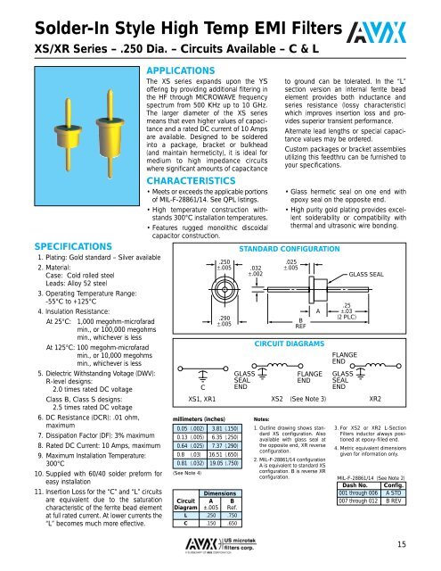
Solder-In Style High Temp <strong>EMI</strong> <strong>Filters</strong><br />
XS/XR Series – .250 Dia. – Circuits Available – C & L<br />
SPECIFICATIONS<br />
1. Plating: Gold standard – Silver available<br />
2. Material:<br />
Case: Cold rolled steel<br />
Leads: Alloy 52 steel<br />
3. Operating Temperature Range:<br />
-55°C to +125°C<br />
4. Insulation Resistance:<br />
At 25°C: 1,000 megohm-microfarad<br />
min., or 100,000 megohms<br />
min., whichever is less<br />
At 125°C: 100 megohm-microfarad<br />
min., or 10,000 megohms<br />
min., whichever is less<br />
5. Dielectric Withstanding Voltage (DWV):<br />
R-level designs:<br />
2.0 times rated DC voltage<br />
Class B, Class S designs:<br />
2.5 times rated DC voltage<br />
6. DC Resistance (DCR): .01 ohm,<br />
maximum<br />
7. Dissipation Factor (DF): 3% maximum<br />
8. Rated DC Current: 10 Amps, maximum<br />
9. Maximum Installation Temperature:<br />
300°C<br />
10. Supplied with 60/40 solder preform for<br />
easy installation<br />
11. Insertion Loss for the “C” and “L” circuits<br />
are equivalent due to the saturation<br />
characteristic of the ferrite bead element<br />
at full rated current. At lower currents the<br />
“L” becomes much more effective.<br />
APPLICATIONS<br />
The XS series expands upon the YS<br />
offering by providing additional filtering in<br />
the HF through MICROWAVE frequency<br />
spectrum from 500 KHz up to 10 GHz.<br />
The larger diameter of the XS series<br />
means that even higher values of capacitance<br />
and a rated DC current of 10 Amps<br />
are available. Designed to be soldered<br />
into a package, bracket or bulkhead<br />
(and maintain hermeticity), it is ideal for<br />
medium to high impedance circuits<br />
where significant amounts of capacitance<br />
CHARACTERISTICS<br />
• Meets or exceeds the applicable portions<br />
of MIL-F-28861/14. See QPL listings.<br />
• High temperature construction withstands<br />
300°C installation temperatures.<br />
• Features rugged monolithic discoidal<br />
capacitor construction.<br />
C<br />
XS1, XR1<br />
.250<br />
±.005<br />
.290<br />
±.005<br />
millimeters (inches)<br />
0.05 (.002) 3.81 (.150)<br />
0.13 (.005) 6.35 (.250)<br />
0.64 (.025) 7.37 (.290)<br />
0.8 (.03) 16.51 (.650)<br />
0.81 (.032) 19.05 (.750)<br />
(See Note 4)<br />
Dimensions<br />
Circuit A B<br />
Diagram ±.005 Ref.<br />
L .250 .750<br />
C .150 .650<br />
.032<br />
±.002<br />
to ground can be tolerated. In the “L”<br />
section version an internal ferrite bead<br />
element provides both inductance and<br />
series resistance (lossy characteristic)<br />
which improves insertion loss and provides<br />
superior transient performance.<br />
Alternate lead lengths or special capacitance<br />
values may be ordered.<br />
Custom packages or bracket assemblies<br />
utilizing this feedthru can be furnished to<br />
your specifications.<br />
• Glass hermetic seal on one end with<br />
epoxy seal on the opposite end.<br />
• High purity gold plating provides excellent<br />
solderability or compatibility with<br />
thermal and ultrasonic wire bonding.<br />
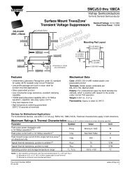
STANDARD CONFIGURATION<br />
GLASS<br />
SEAL<br />
END<br />
.025<br />
±.005<br />
B<br />
REF<br />
Notes:<br />
1. Outline drawing shows standard<br />
XS configuration. Also<br />
available with glass seal at<br />
the opposite end, XR reverse<br />
configuration.<br />
2. MIL-F-28861/14 configuration<br />
A is equivalent to standard XS<br />
configuration. B is reverse XR<br />
configuration.<br />
A<br />
CIRCUIT DIAGRAMS<br />
FLANGE<br />
END<br />
XS2 (See Note 3)<br />
.25<br />
±.03<br />
(2 PLC)<br />
FLANGE<br />
END<br />
GLASS<br />
SEAL<br />
END<br />
GLASS SEAL<br />
XR2<br />
3. For XS2 or XR2 L-Section<br />
<strong>Filters</strong> inductor always positioned<br />
at epoxy-filled end.<br />
4. Metric equivalent dimensions<br />
given for information only.<br />
MIL-F-28861/14 (See Note 2)<br />
Dash No. Config.<br />
001 through 006 A STD<br />
007 through 012 B REV<br />
15