AVX US Microtek EMI Filters Catalog - RYSTON Electronics sro
AVX US Microtek EMI Filters Catalog - RYSTON Electronics sro
AVX US Microtek EMI Filters Catalog - RYSTON Electronics sro

Create successful ePaper yourself
Turn your PDF publications into a flip-book with our unique Google optimized e-Paper software.
Advanced Technology <strong>Filters</strong><br />
Miniature – .075 Dia. - High Temperature Solder-In<br />
GENERAL DESCRIPTION<br />
<strong>AVX</strong>’s new MiniGuard Filter breaks the<br />
“small” size barrier. This microminiature<br />
solder-in has a case diameter of only<br />
.075". This is a 60% reduction in size<br />
from <strong>AVX</strong>’s previously smallest filter. An<br />
<strong>AVX</strong> proprietary manufacturing breakthrough<br />
has permitted downsizing the<br />
filter by providing highly reproducible and<br />
reliable .050" diameter MLC discoidals. In<br />
addition, the MiniGuard has a matched<br />
hermetic glass-to-metal seal on one end,<br />
and utilizes <strong>AVX</strong>’s patented non-solder<br />
construction. This technology allows<br />
installation temperatures of 300°C and<br />
eliminates the possibility of internal solder<br />
reflow. Ideal for small microwave packages,<br />
medical electronics, satellites or<br />
other applications where space is at a<br />
premium.<br />
SPECIFICATIONS<br />
1. Finish: Gold<br />
2. Material:<br />
Case: Kovar<br />
Leads: Kovar<br />
3. Operating Temperature Range:<br />
-55°C to +125°C<br />
4. Insulation Resistance:<br />
At 25°C: 1,000 megohm-microfarad<br />
min., or 100,000 megohms<br />
min., whichever is less<br />
At 125°C: 100 megohm-microfarad<br />
min., or 10,000 megohms<br />
min., whichever is less<br />
5. Dielectric Withstanding Voltage (DWV):<br />
2.0 times rated DC voltage<br />
6. DC Resistance (DCR): .02 Ω maximum<br />
7. Dissipation Factor (DF): 3% maximum<br />
8. Rated DC Current: 1.5 Amps, maximum<br />
9. Maximum Installation Temperature: 300°C<br />
10. Supplied with 60/40 solder preform for easy<br />
installation<br />
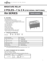
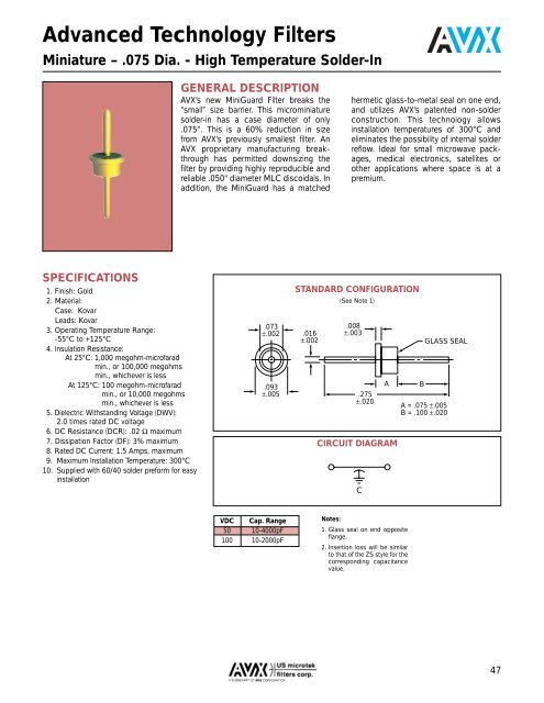
.073<br />
±.002<br />
.093<br />
±.005<br />
STANDARD CONFIGURATION<br />
.016<br />
±.002<br />
(See Note 1)<br />
.008<br />
±.003<br />
.275<br />
±.020<br />
A<br />
CIRCUIT DIAGRAM<br />
C<br />
B<br />
GLASS SEAL<br />
A = .075 ±.005<br />
B = .100 ±.020<br />
VDC Cap. Range<br />
50 10-4000pF<br />
100 10-2000pF<br />
Notes:<br />
1. Glass seal on end opposite<br />
flange.<br />
2. Insertion loss will be similar<br />
to that of the ZS style for the<br />
corresponding capacitance<br />
value.<br />
47