AVX US Microtek EMI Filters Catalog - RYSTON Electronics sro
AVX US Microtek EMI Filters Catalog - RYSTON Electronics sro
AVX US Microtek EMI Filters Catalog - RYSTON Electronics sro

Create successful ePaper yourself
Turn your PDF publications into a flip-book with our unique Google optimized e-Paper software.
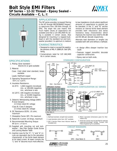
Bolt Style <strong>EMI</strong> <strong>Filters</strong><br />
SP Series – 12-32 Thread - Epoxy Sealed –<br />
Circuits Available – C, L, π<br />
SPECIFICATIONS<br />
1. Plating: Silver standard –<br />
Electro-tin or gold available<br />
2. Material:<br />
Case: Cold rolled steel standard, brass<br />
available<br />
Leads: Half/hard copper<br />
3. Operating Temperature Range:<br />
-55°C to +125°C<br />
4. Insulation Resistance:<br />
At 25°C: 1,000 megohm-microfarad<br />
min., or 100,000 megohms<br />
min., whichever is less<br />
At 125°C: 100 megohm-microfarad<br />
min., or 10,000 megohms<br />
min., whichever is less<br />
5. Dielectric Withstanding Voltage (DWV):<br />
R-level designs:<br />
2.0 times rated DC voltage<br />
Class B, Class S designs:<br />
2.5 times rated DC voltage<br />
6. DC Resistance (DCR): .01 ohm,<br />
maximum<br />
7. Dissipation Factor (DF): 3% maximum<br />
8. Rated DC Current: 10 Amps, maximum<br />
9. Recommended Mounting Torque:<br />
64 oz-in. ± 4 oz-in.<br />
10. Supplied with mounting nut and lockwasher<br />
- See Filter Design Guide Screw<br />
and Locking Washer Table<br />
11. Insertion Loss for the “C”, “L” and “π” circuits<br />
are equivalent due to the saturation<br />
characteristic of the ferrite bead element<br />
at full rated current. At lower currents the<br />
“L” and “π” become much more effective.<br />
APPLICATIONS<br />
The SP series provides increased filtering<br />
in the HF through MICROWAVE frequency<br />
spectrums from 100 KHz through 10<br />
GHz. The larger hex size means that<br />
much higher values of capacitance are<br />
available and that a 125 VAC/400 Hz rating<br />
is available in certain values. Also<br />
designed for mounting in a tapped bulkhead<br />
or with the standard nut and lockwasher<br />
provided, it is optimum in medium<br />
CHARACTERISTICS<br />
• Designed to meet or exceed the applicable<br />
portions of MIL-F-28861/9. See QPL<br />
listing.<br />
• Conservatively rated for 125 VAC/400<br />
Hz in certain values.<br />
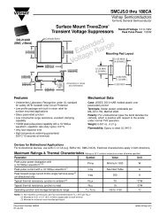
.250<br />
±.010<br />
(Std. - See Note 1)<br />
millimeters (inches)<br />
0.05 (.002) 2.36 (.093)<br />
0.13 (.005) 3.99 (.157)<br />
0.18 (.007) 4.75 (.187)<br />
0.25 (.010) 5.49 (.216)<br />
0.51 (.020) 6.12 (.241)<br />
0.58 (.023) 6.35 (.250)<br />
0.79 (.031) 7.90 (.311)<br />
0.81 (.032) 8.71 (.343)<br />
1.02 (.040) 9.45 (.372)<br />
1.14 (.045) 9.73 (.383)<br />
1.60 (.063) 23.39 (.921)<br />
1.85 (.073) — —<br />
(See Note 4)<br />
.045<br />
.157<br />
.020<br />
±.005<br />
.343<br />
±.020<br />
(See Note 5)<br />
.187<br />
±.005<br />
.250 DIA.<br />
±.005<br />
Notes:<br />
1. Nailhead standard, straight lead available.<br />
2. Lead diameters other than .032" available.<br />
3. SP2 L-Section <strong>Filters</strong> have inductor (bead) at<br />
threaded end.<br />
C<br />
SP1<br />
to low impedance circuits where significant<br />
amounts of capacitance to ground can<br />
be tolerated. In the “L” and “π” section<br />
versions an internal ferrite bead element<br />
provides both inductance and series<br />
resistance (lossy characteristic) which<br />
improves the insertion loss rolloff to 40 dB<br />
and 60 dB per decade respectively.<br />
Alternate lead diameters or lengths are<br />
available both with and without a nailhead.<br />
• π design offers steeper insertion loss<br />
rolloff.<br />
• Features rugged monolithic discoidal<br />
capacitor construction.<br />
• Epoxy seal on both ends.<br />
STANDARD CONFIGURATION<br />
.040<br />
MAX.<br />
.250<br />
.311<br />
.921<br />
±.020<br />
.093<br />
MAX.<br />
.032<br />
±.005<br />
.157<br />
±.005<br />
.343<br />
±.020<br />
CIRCUIT DIAGRAMS<br />
.216 UNEF-2A<br />
(12-32)<br />
.032 ±.002<br />
(Std. - See Note 2)<br />
ALTERNATE CONFIGURATION (SC SERIES)<br />
THRD<br />
END L 2<br />
.250<br />
±.005<br />
.311<br />
±.005<br />
.921<br />
±.020<br />
12-32 UNEF-2A<br />
20 GAUGE<br />
(.032)<br />
4. Metric equivalent dimensions given for information<br />
only.<br />
5. Small-hex version may be specified for selected<br />
capacitance/voltage ratings. Contact <strong>AVX</strong><br />
<strong>Filters</strong> Engineering for availability.<br />
SP2 (See Note 3)<br />
Pi<br />
SP3<br />
25