AVX US Microtek EMI Filters Catalog - RYSTON Electronics sro
AVX US Microtek EMI Filters Catalog - RYSTON Electronics sro
AVX US Microtek EMI Filters Catalog - RYSTON Electronics sro

You also want an ePaper? Increase the reach of your titles
YUMPU automatically turns print PDFs into web optimized ePapers that Google loves.
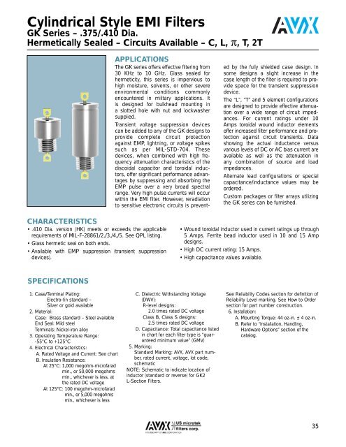
Cylindrical Style <strong>EMI</strong> <strong>Filters</strong><br />
GK Series – .375/.410 Dia.<br />
Hermetically Sealed – Circuits Available – C, L, π, T, 2T<br />
APPLICATIONS<br />
The GK series offers effective filtering from<br />
30 KHz to 10 GHz. Glass sealed for<br />
hermeticity, this series is impervious to<br />
high moisture, solvents, or other severe<br />
environmental conditions commonly<br />
encountered in military applications. It<br />
is designed for bulkhead mounting in<br />
a slotted hole with nut and lockwasher<br />
supplied.<br />
Transient voltage suppression devices<br />
can be added to any of the GK designs to<br />
provide complete circuit protection<br />
against EMP, lightning, or voltage spikes<br />
such as per MIL-STD-704. These<br />
devices, when combined with high frequency<br />
attenuation characteristics of the<br />
discoidal capacitor and toroidal inductors,<br />
offer significant performance advantages<br />
by suppressing and absorbing the<br />
EMP pulse over a very broad spectral<br />
range. Very high pulse currents will occur<br />
within the <strong>EMI</strong> filter. However, reradiation<br />
to sensitive electronic circuits is prevented<br />
by the fully shielded case design. In<br />
some designs a slight increase in the<br />
case length of the filter is required to provide<br />
space for the transient suppression<br />
device.<br />
The “L”, “T” and 5 element configurations<br />
are designed to provide effective attenuation<br />
over a wide range of circuit impedances.<br />
For current ratings under 10<br />
Amps toroidal wound inductor elements<br />
offer increased filter performance and protection<br />
against circuit transients. Data<br />
showing the actual inductance versus<br />
various levels of DC or AC bias current are<br />
available as well as the attenuation in<br />
any combination of source and load<br />
impedances.<br />
Alternate lead configurations or special<br />
capacitance/inductance values may be<br />
ordered.<br />
Custom packages or filter arrays utilizing<br />
the GK series can be furnished.<br />
CHARACTERISTICS<br />
• .410 Dia. version (HK) meets or exceeds the applicable<br />
requirements of MIL-F-28861/2,/3,/4,/5. See QPL listing.<br />
• Glass hermetic seal on both ends.<br />
• Available with EMP suppression (transient suppression<br />
devices).<br />
• Wound toroidal inductor used in current ratings up through<br />
5 Amps. Ferrite bead inductor used in 10 and 15 Amp<br />
designs.<br />
• High DC current rating: 15 Amps.<br />
• High capacitance values available.<br />
SPECIFICATIONS<br />
1. Case/Terminal Plating:<br />
Electro-tin standard –<br />
Silver or gold available<br />
2. Material:<br />
Case: Brass standard – Steel available<br />
End Seal: Mild steel<br />
Terminals: Nickel-iron alloy<br />
3. Operating Temperature Range:<br />
-55°C to +125°C<br />
4. Electrical Characteristics:<br />
A. Rated Voltage and Current: See chart<br />
B. Insulation Resistance:<br />
At 25°C: 1,000 megohm-microfarad<br />
min., or 50,000 megohms<br />
min., whichever is less, at<br />
the rated DC voltage<br />
At 125°C: 100 megohm-microfarad<br />
min., or 5,000 megohms<br />
min., whichever is less<br />
C. Dielectric Withstanding Voltage<br />
(DWV):<br />
R-level designs:<br />
2.0 times rated DC voltage<br />
Class B, Class S designs:<br />
2.5 times rated DC voltage<br />
D. Capacitance: Total capacitance listed<br />
in chart for each filter type is “guaranteed<br />
minimum value” (GMV)<br />
5. Marking:<br />
Standard Marking: <strong>AVX</strong>, <strong>AVX</strong> part number,<br />
rated current, voltage, lot code,<br />
schematic<br />
NOTE: Schematic to indicate location of<br />
inductor (standard or reverse) for GK2<br />
L-Section <strong>Filters</strong>.<br />
See Reliability Codes section for definition of<br />
Reliability Level marking. See How to Order<br />
section for part number construction.<br />
6. Installation:<br />
A. Mounting Torque: 44 oz-in. ± 4 oz-in.<br />
B. Refer to “Installation, Handling,<br />
Hardware Options” section of the<br />
catalog.<br />
35