AVX US Microtek EMI Filters Catalog - RYSTON Electronics sro
AVX US Microtek EMI Filters Catalog - RYSTON Electronics sro
AVX US Microtek EMI Filters Catalog - RYSTON Electronics sro

You also want an ePaper? Increase the reach of your titles
YUMPU automatically turns print PDFs into web optimized ePapers that Google loves.
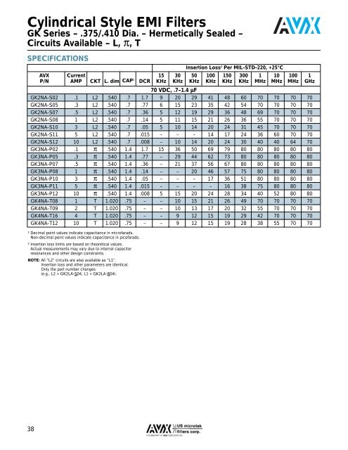
Cylindrical Style <strong>EMI</strong> <strong>Filters</strong><br />
GK Series – .375/.410 Dia. – Hermetically Sealed –<br />
Circuits Available – L, π, T<br />
SPECIFICATIONS<br />
Insertion Loss 2 Per MIL-STD-220, +25°C<br />
<strong>AVX</strong> Current 15 30 50 100 150 300 1 10 100 1<br />
P/N AMP CKT L. dim CAP 1 DCR KHz KHz KHz KHz KHz KHz MHz MHz MHz GHz<br />
70 VDC, .7–1.4 µF<br />
GK2NA-S02 .1 L2 .540 .7 1.7 9 20 29 41 48 60 70 70 70 70<br />
GK2NA-S05 .3 L2 .540 .7 .77 6 15 23 35 42 54 70 70 70 70<br />
GK2NA-S07 .5 L2 .540 .7 .36 5 12 19 29 36 48 69 70 70 70<br />
GK2NA-S08 1 L2 .540 .7 .14 5 11 15 21 26 36 55 70 70 70<br />
GK2NA-S10 3 L2 .540 .7 .05 5 10 14 20 24 31 45 70 70 70<br />
GK2NA-S11 5 L2 .540 .7 .015 – – – 14 17 24 36 60 70 70<br />
GK2NA-S12 10 L2 .540 .7 .008 – 10 14 20 24 30 40 40 64 70<br />
GK3NA-P02 .1 π .540 1.4 1.7 15 36 50 69 79 80 80 80 80 80<br />
GK3NA-P05 .3 π .540 1.4 .77 – 29 44 62 73 80 80 80 80 80<br />
GK3NA-P07 .5 π .540 1.4 .36 – 21 37 56 67 80 80 80 80 80<br />
GK3NA-P08 1 π .540 1.4 .14 – – 20 46 57 75 80 80 80 80<br />
GK3NA-P10 3 π .540 1.4 .05 – – – 17 36 51 80 80 80 80<br />
GK3NA-P11 5 π .540 1.4 .015 – – – – 16 38 75 80 80 80<br />
GK3NA-P12 10 π .540 1.4 .008 5 15 20 24 28 34 40 52 80 80<br />
GK4NA-T08 1 T 1.020 .75 – – 10 15 21 26 49 70 70 70 70<br />
GK4NA-T09 2 T 1.020 .75 – – 10 13 17 20 32 55 70 70 70<br />
GK4NA-T16 4 T 1.020 .75 – – 9 12 15 19 29 42 70 70 70<br />
GK4NA-T12 10 T 1.020 .75 – – 9 12 15 19 28 38 55 70 70<br />
1 Decimal point values indicate capacitance in microfarads.<br />
Non-decimal point values indicate capacitance in picofarads.<br />
2 Insertion loss limits are based on theoretical values.<br />
Actual measurements may vary due to internal capacitor<br />
resonances and other design constraints.<br />
NOTE: All “L2” circuits are also available as “L1”.<br />
Insertion loss and other parameters are identical.<br />
Only the part number changes<br />
(e.g., L2 = GK2LA-S04, L1 = GK2LA-R04).<br />
38