AVX US Microtek EMI Filters Catalog - RYSTON Electronics sro
AVX US Microtek EMI Filters Catalog - RYSTON Electronics sro
AVX US Microtek EMI Filters Catalog - RYSTON Electronics sro

Create successful ePaper yourself
Turn your PDF publications into a flip-book with our unique Google optimized e-Paper software.
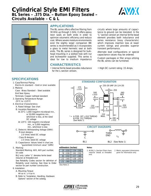
Cylindrical Style <strong>EMI</strong> <strong>Filters</strong><br />
BL Series – .375 Dia. – Button Epoxy Sealed –<br />
Circuits Available – C & L<br />
APPLICATIONS<br />
The BL series offers effective filtering from<br />
30 KHz up through 1 GHz. It offers epoxy<br />
resin seals on both ends in order to<br />
optimize volumetric efficiency and reduce<br />
cost. Where severe moisture environments<br />
exist the slightly larger companion BK<br />
series is recommended as it incorporates<br />
a glass to metal hermetic seal at both<br />
ends. The BL series is designed for bulkhead<br />
mounting in a slotted hole with nut<br />
and lockwasher supplied. This series is<br />
ideal for low to medium impedance<br />
CHARACTERISTICS<br />
• Internal ferrite bead provides inductance<br />
for the L-section version.<br />
circuits where large amounts of capacitance<br />
to ground can be tolerated. In the<br />
“L” section version an internal ferrite bead<br />
element provides both inductance and<br />
series resistance (lossy characteristic)<br />
which improves insertion loss at lower<br />
current ratings and provides superior<br />
transient performance.<br />
Alternate lead configurations or special<br />
capacitance values may be ordered.<br />
Custom packages or filter arrays utilizing<br />
the BL series can be furnished.<br />
• High DC current rating: 15 Amps.<br />
SPECIFICATIONS<br />
1. Case/Terminal Plating:<br />
Electro-tin standard – Gold or silver available<br />
2. Material:<br />
Case: Brass Standard – Steel available<br />
End Seal: Epoxy<br />
Terminals: Copper nailhead standard<br />
3. Operating Temperature Range:<br />
-55°C to +125°C<br />
4. Electrical Characteristics:<br />
A. Rated Voltage: See chart<br />
B. Insulation Resistance:<br />
At 25°C: 1,000 megohm-microfarad min.,<br />
or 50,000 megohms min.,<br />
whichever is less, at the rated<br />
DC voltage<br />
At 125°C: 100 megohm-microfarad<br />
min., or 5,000 megohms<br />
min., whichever is less<br />
C. Dielectric Withstanding Voltage (DWV):<br />
R-level designs:<br />
2.0 times rated DC voltage<br />
Class B designs:<br />
2.5 times rated DC voltage<br />
D. Capacitance: Values listed in chart are<br />
“guaranteed minimum value” (GMV)<br />
5. Marking:<br />
Standard Marking: <strong>AVX</strong>, <strong>AVX</strong> part number,<br />
lot code<br />
BL2 only: Letter “L” denotes ferrite bead<br />
inductor at threaded end<br />
See Reliability Codes section for definition of<br />
Reliability Level marking. See How to Order<br />
section for part number construction.<br />
6. Installation:<br />
A. Mounting Torque:<br />
44 oz-in. ± 4 oz-in.<br />
B. Refer to “Installation, Handling, Hardware<br />
Options” section of the catalog.<br />
millimeters (inches)<br />
.375<br />
±.010<br />
.200<br />
±.010<br />
.040<br />
±.010<br />
.150<br />
±.032<br />
* = A FOR .187 ±.010 THREAD<br />
B FOR .312 THREAD<br />
(See Note 1)<br />
.25 (.010) 2.54 (.100)<br />
.76 (.030) 3.81 (.150)<br />
.81 (.032) 4.57 (.180)<br />
1.02 (.040) 5.08 (.200)<br />
1.52 (.060) 9.53 (.375)<br />
(See Note 2)<br />
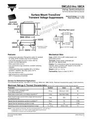
STANDARD CONFIGURATION<br />
C<br />
BL1<br />
250-28 UNF-2A (1/4-28)<br />
.150<br />
MAX.<br />
*<br />
±.010<br />
CIRCUIT DIAGRAMS<br />
Notes:<br />
1. All BL2 L-Section <strong>Filters</strong> have<br />
inductor (bead) at threaded<br />
end.<br />
.050<br />
.280<br />
±.032<br />
THRD<br />
END L 2<br />
.060<br />
REF.<br />
.030<br />
±.010<br />
BL2 (See Note 1)<br />
2. Metric equivalent dimensions<br />
given for information only.<br />
29