Saab 400130217 instructions in English - SaabDocs.com
Saab 400130217 instructions in English - SaabDocs.com
Saab 400130217 instructions in English - SaabDocs.com

You also want an ePaper? Increase the reach of your titles
YUMPU automatically turns print PDFs into web optimized ePapers that Google loves.
SCdefault<br />
9-5 Installation <strong><strong>in</strong>structions</strong><br />
SITdefault<br />
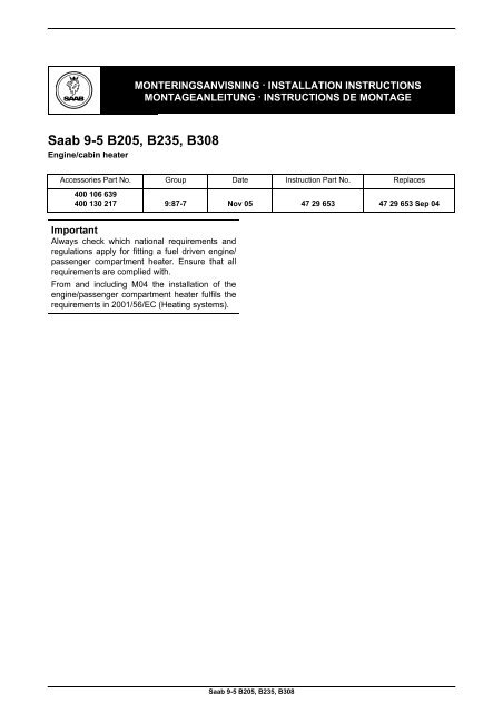
<strong>Saab</strong> 9-5 B205, B235, B308<br />
Eng<strong>in</strong>e/cab<strong>in</strong> heater<br />
MONTERINGSANVISNING · INSTALLATION INSTRUCTIONS<br />
MONTAGEANLEITUNG · INSTRUCTIONS DE MONTAGE<br />
Accessories Part No. Group Date Instruction Part No. Replaces<br />
400 106 639<br />
400 130 217 9:87-7 Nov 05 47 29 653 47 29 653 Sep 04<br />
Important<br />
Always check which national requirements and<br />
regulations apply for fitt<strong>in</strong>g a fuel driven eng<strong>in</strong>e/<br />
passenger <strong>com</strong>partment heater. Ensure that all<br />
requirements are <strong>com</strong>plied with.<br />
From and <strong>in</strong>clud<strong>in</strong>g M04 the <strong>in</strong>stallation of the<br />
eng<strong>in</strong>e/passenger <strong>com</strong>partment heater fulfils the<br />
requirements <strong>in</strong> 2001/56/EC (Heat<strong>in</strong>g systems).<br />
<strong>Saab</strong> 9-5 B205, B235, B308
2 47 29 653<br />
1 2<br />
4<br />
3<br />
5<br />
Vid tankn<strong>in</strong>g måste värmaren<br />
vara frånkopplad<br />
Switch off the heater<br />
when add<strong>in</strong>g fuel<br />
E980A222<br />
Heater kit 400 106 621 conta<strong>in</strong>s:<br />
1 Petrol heater<br />
2 Circulation pump<br />
3 Non-return valve<br />
4 Fuel Pump<br />
5 Label<br />
<strong>Saab</strong> 9-5 B205, B235, B308
47 29 653 3<br />
19<br />
6<br />
9<br />
13<br />
11<br />
20<br />
3<br />
14<br />
7<br />
10<br />
3<br />
5<br />
22<br />
16<br />
15 12<br />
4<br />
8<br />
21<br />
18<br />
17<br />
2<br />
1<br />
E980A125<br />
Mount<strong>in</strong>g kit 400 106 639 conta<strong>in</strong>s:<br />
1 Bracket<br />
2 Holder<br />
3 Coolant hoses (x3)<br />
4 Silencer<br />
5 Exhaust pipe 90°<br />
6 Clip (exhaust hose) (x2)<br />
7 Exhaust hose<br />
8 Intake hose<br />
9 Holder, coolant pump<br />
10 Splash guard<br />
11 Clips (x4)<br />
12 Screw (x3)<br />
13 Hose clip (x8)<br />
14 Cable tie (x2)<br />
15 Screw, M6<br />
16 Screw (x9)<br />
17 Screw M8 (x4)<br />
18 Nut M6<br />
19 Clamp (x3) (exhaust pipe)<br />
20 Clamp (<strong>in</strong>take)<br />
21 Bl<strong>in</strong>d rivet (x2)<br />
22 Screw M6 (x2)<br />
<strong>Saab</strong> 9-5 B205, B235, B308
4 47 29 653<br />
3<br />
23<br />
19<br />
6<br />
9<br />
13<br />
11<br />
20<br />
3<br />
14<br />
7<br />
10<br />
5<br />
22<br />
16<br />
15 12<br />
4<br />
8<br />
21<br />
18<br />
17<br />
2<br />
1<br />
E980A340<br />
Mount<strong>in</strong>g kit 400 130 217 conta<strong>in</strong>s:<br />
1 Bracket<br />
2 Holder<br />
3 Coolant hoses (x3)<br />
4 Silencer<br />
5 Exhaust pipe 90°<br />
6 Clip (exhaust hose) (x2)<br />
7 Exhaust hose<br />
8 Intake hose<br />
9 Holder, coolant pump<br />
10 Splash guard<br />
11 Clips (x4)<br />
12 Screw (x3)<br />
13 Hose clip (x8)<br />
14 Cable tie (x2)<br />
15 Screw, M6<br />
16 Screw (x9)<br />
17 Screw M8 (x4)<br />
18 Nut M6<br />
19 Clamp (exhaust pipe)<br />
20 Clamp (<strong>in</strong>take)<br />
21 Bl<strong>in</strong>d rivet (x2)<br />
22 Screw M6 (x2)<br />
23 Clamp (x2) (exhaust pipe)<br />
<strong>Saab</strong> 9-5 B205, B235, B308
47 29 653 5<br />
1<br />
2 4 5<br />
12 13<br />
3<br />
6 11 8<br />
14<br />
7<br />
9<br />
10<br />
E980A341<br />
Fuel connection kit 400 126 363 conta<strong>in</strong>s:<br />
1 Fuel l<strong>in</strong>e (x2)<br />
2 Junction hose, angled (x2)<br />
3 Clamp (x2)<br />
4 Junction hose, angled<br />
5 Fuel connection kit (tank)<br />
6 Bracket, fuel pump<br />
7 Clamp<br />
8 Rubber spacer<br />
9 Cable tie (x10)<br />
10 Cable tie<br />
11 Screw (x2)<br />
12 Hose clip (x4)<br />
13 Clamp (x3)<br />
14 Nut (x3)<br />
<strong>Saab</strong> 9-5 B205, B235, B308
6 47 29 653<br />
2<br />
5<br />
1<br />
3<br />
4 6<br />
E980A127<br />
Electric connection kit 400 106 654 conta<strong>in</strong>s:<br />
1 Wir<strong>in</strong>g harness<br />
2 Connector 2-p<strong>in</strong><br />
3 Cable tie (x11)<br />
4 Screw (x2)<br />
5 Bracket<br />
6 Grommet (x2)<br />
<strong>Saab</strong> 9-5 B205, B235, B308
47 29 653 7<br />
2<br />
4<br />
1<br />
3<br />
5 6<br />
E980A342<br />
Electric connection kit 400 130 225 conta<strong>in</strong>s:<br />
1 Wir<strong>in</strong>g harness<br />
2 Connector 2-p<strong>in</strong><br />
3 Cable tie (x11)<br />
4 Relay<br />
5 Fuse 15A<br />
6 Grommet (x2)<br />
<strong>Saab</strong> 9-5 B205, B235, B308
8 47 29 653<br />
E980A494<br />
Additional kit 32 000 515 conta<strong>in</strong>s:<br />
Cable term<strong>in</strong>al<br />
<strong>Saab</strong> 9-5 B205, B235, B308
47 29 653 9<br />
Safety regulations<br />
WARNING<br />
Read through the entire <strong>in</strong>stallation <strong><strong>in</strong>structions</strong><br />
before beg<strong>in</strong>n<strong>in</strong>g work.<br />
Work when <strong>in</strong>stall<strong>in</strong>g the heater <strong>in</strong>volves <strong>in</strong>terference<br />
with the fuel system. Please observe the follow<strong>in</strong>g<br />
po<strong>in</strong>ts <strong>in</strong> connection with assembly:<br />
Provide good ventilation. If approved fuel fume<br />
extractors are available, then they should be<br />
used.<br />
Use protective gloves! Prolonged contact with<br />
fuel can cause sk<strong>in</strong> irritation.<br />
Keep a class BE fire ext<strong>in</strong>guisher near at hand.<br />
Be m<strong>in</strong>dful of the danger of sparks occurr<strong>in</strong>g<br />
when mak<strong>in</strong>g and break<strong>in</strong>g electric circuits, <strong>in</strong><br />
the event of a short circuit, etc.<br />
Smok<strong>in</strong>g is prohibited.<br />
Assembly of the heater should be performed by<br />
qualified staff and <strong>in</strong> accordance with the <strong>in</strong>stallation<br />
<strong><strong>in</strong>structions</strong>.<br />
Important<br />
All ends must meet <strong>com</strong>pletely when jo<strong>in</strong><strong>in</strong>g fuel<br />
l<strong>in</strong>es <strong>in</strong> this kit.<br />
The heater should never be used <strong>in</strong> an enclosed<br />
space, like the garage or workshop, without the<br />
exhaust ventilation be<strong>in</strong>g used.<br />
Always turn off the heater <strong>in</strong> service stations and<br />
similar premises.<br />
Important<br />
When the heater is be<strong>in</strong>g used as a park<strong>in</strong>g<br />
heater, it will consume some of the battery's<br />
capacity. This is especially evident <strong>in</strong> cold weather<br />
when the battery is already under hard stra<strong>in</strong>. It is<br />
therefore re<strong>com</strong>mended that with ambient temperatures<br />
down to -20°, to drive the car for at least the<br />
same length of time as the heater has been runn<strong>in</strong>g.<br />
At lower temperatures we re<strong>com</strong>mend not<br />
us<strong>in</strong>g the heater for longer than 30 m<strong>in</strong>utes. The<br />
battery should also be checked at regular <strong>in</strong>tervals<br />
and recharged as necessary.<br />
The heater should be activated at least once a<br />
month, even dur<strong>in</strong>g the summer. This will prevent<br />
fuel left <strong>in</strong> the l<strong>in</strong>es from evaporat<strong>in</strong>g and leav<strong>in</strong>g<br />
deposits that can cause operational problems.<br />
<strong>Saab</strong> 9-5 B205, B235, B308
10 47 29 653<br />
4<br />
5<br />
4 6<br />
7<br />
2<br />
3<br />
7<br />
7<br />
3 E980A343<br />
1 Check the radio code and make a note of it if the<br />
car is equipped with a radio other than <strong>Saab</strong><br />
Audio System.<br />
2 LHD: Remove the sound baffle under the lefthand<br />
side of the dashboard <strong>in</strong>clud<strong>in</strong>g the data<br />
l<strong>in</strong>k connector and floor light<strong>in</strong>g where appropriate.<br />
RHD: Remove the glove box.<br />
3 Remove the left-hand sill protection strip, h<strong>in</strong>ge<br />
forward the back seat cushions, free the connector<br />
hous<strong>in</strong>g of the left-hand back-seat cushion<br />
heater (if fitted) and lift out the left-hand section<br />
of the back seat. Fold back the mat and<br />
remove the tank access cover.<br />
4 Remove the battery cover, battery cables and<br />
the battery.<br />
M02-: Remove the battery tray.<br />
5 Undo and push aside the expansion tank.<br />
6 M02-: Open the lid of the electrical centre and lift<br />
up the relay mount<strong>in</strong>g plate by push<strong>in</strong>g <strong>in</strong> the<br />
four reta<strong>in</strong><strong>in</strong>g catches<br />
7 M02-: Detach and lift up the eng<strong>in</strong>e bay electrical<br />
centre. Remove the cable tie from the electrical<br />
centre's mount<strong>in</strong>g bracket and lift away the<br />
electrical centre.<br />
<strong>Saab</strong> 9-5 B205, B235, B308
47 29 653 11<br />
-MY01<br />
MY02-<br />
8<br />
9<br />
9<br />
8<br />
8<br />
8<br />
8 8 8<br />
E980A344<br />
8 -M01: Remove the grille, headlamp surrounds,<br />
<strong>in</strong>dicator lights and the headlamps. Undo the<br />
left-hand headlamp wiper motor.<br />
Important<br />
If a spacer washer is fitted between the headlamp<br />
and the body frame it must be reta<strong>in</strong>ed for refitt<strong>in</strong>g<br />
when the headlamp is refitted.<br />
M02-05: Remove both the outer grille segments,<br />
<strong>in</strong>dicator lights, headlamps and the<br />
headlamp washer covers.<br />
9 Us<strong>in</strong>g white spirit, clean an area on the left-hand<br />
front w<strong>in</strong>g, level with the cool<strong>in</strong>g system's<br />
expansion tank. Peel off the extra label from the<br />
heater and affix it to the cleaned area.<br />
Important<br />
Under no circumstances may this label conceal<br />
any part of another label or plate.<br />
<strong>Saab</strong> 9-5 B205, B235, B308
12 47 29 653<br />
-MY01<br />
10<br />
12<br />
12<br />
MY02-<br />
12<br />
13<br />
12 12 12<br />
13<br />
E980A345<br />
10 Raise the car.<br />
WARNING<br />
Locate the right-hand lift<strong>in</strong>g po<strong>in</strong>t as far out as possible<br />
<strong>in</strong> order to allow room for mount<strong>in</strong>g the fuel<br />
pump.<br />
Remove the front spoiler shield.<br />
11 Where fitted, remove the eng<strong>in</strong>e-block heater<br />
plug from the bumper.<br />
12 -M01: Remove the 4 screws which fix the<br />
bumper to the bumper beam and the nuts which<br />
hold the bumper to the front w<strong>in</strong>g.<br />
M02-05: Remove the 6 screws which fix the<br />
bumper to the bumper beam and the 5 clips<br />
above the grille.<br />
13 -M05: Remove the 6 screws (3 on each side)<br />
where the bumper is attached to the w<strong>in</strong>g l<strong>in</strong>ers.<br />
14 M98: Where fog lights or a temperature sensor<br />
have been fitted disconnect their respective<br />
cables.<br />
M99-01: Disconnect the bumper wir<strong>in</strong>g harness<br />
connector. The connector is located under the<br />
left-hand headlamp.<br />
M02-: Disconnect the bumper wir<strong>in</strong>g harness<br />
connector. The connector is located under the<br />
right-hand headlamp.<br />
15 -M05: First loosen the bumper from the front<br />
w<strong>in</strong>gs, on both sides, and then pull the bumper<br />
forwards.<br />
<strong>Saab</strong> 9-5 B205, B235, B308
47 29 653 13<br />
21 21<br />
18<br />
19<br />
17<br />
16<br />
20<br />
22<br />
16<br />
E980A539<br />
16 M06-: Remove the bumper shell screws to the<br />
w<strong>in</strong>g l<strong>in</strong>er on both sides.<br />
17 M06-: Detach the shell from the side bracket on<br />
the left-hand side. Detach the hook us<strong>in</strong>g a<br />
screwdriver.<br />
18 M06-, cars with headlamp washers: Position a<br />
collection conta<strong>in</strong>er under the car. Remove the<br />
hose's quick-release coupl<strong>in</strong>g for the headlamp<br />
washers. Plug the hole for the washer fluid reservoir<br />
connection.<br />
19 M06-: Detach the shell from the side bracket on<br />
the right-hand side. Detach the hook us<strong>in</strong>g a<br />
screwdriver.<br />
20 M06-: Separate the connector for the front<br />
bumper harness.<br />
21 M06-: Remove the bumper shell's upper clips.<br />
Remove the screws.<br />
22 M06-: With help from an assistant, lift off the<br />
bumper shell.<br />
<strong>Saab</strong> 9-5 B205, B235, B308
14 47 29 653<br />
23<br />
23<br />
23<br />
24<br />
24<br />
23<br />
23<br />
24<br />
24<br />
24<br />
E980A540<br />
23 Remove the left-hand front wheel and the lefthand<br />
w<strong>in</strong>g l<strong>in</strong>er.<br />
24 Undo the connections to the pump and the level<br />
sensor. Empty the washer fluid reservoir.<br />
If the reservoir is fixed with bl<strong>in</strong>d rivets they must<br />
be drilled out. Punch out the core p<strong>in</strong> of each<br />
rivet and drill out, us<strong>in</strong>g first a 4 mm bit and then<br />
a 5 mm bit. Remove the washer fluid reservoir.<br />
Important<br />
This method must be employed to prevent damag<strong>in</strong>g<br />
the surround<strong>in</strong>g <strong>com</strong>ponents.<br />
<strong>Saab</strong> 9-5 B205, B235, B308
47 29 653 15<br />
27,29<br />
26<br />
27,29<br />
25<br />
32<br />
35<br />
X<br />
31<br />
32<br />
33<br />
E980A541<br />
25 Hold the bracket <strong>in</strong> front of the press fold on the<br />
chassis plate, see illustration, so that the protrusion<br />
(X) on the bracket fits <strong>in</strong>to the depression <strong>in</strong><br />
the chassis plate. Mark the position of the two<br />
holes on the underside.<br />
26 Drill two 3 mm holes on the underside of the<br />
chassis frame and screw the bracket <strong>in</strong>to position.<br />
27 Drill four 3 mm holes from the side. Remove the<br />
bracket.<br />
28 Deburr the holes and remove loose drill<strong>in</strong>gs and<br />
flakes of pa<strong>in</strong>t. Clean with Teroson FL Cleaner.<br />
Apply Standox 1K Primer Filler. Apply f<strong>in</strong>ish<br />
pa<strong>in</strong>t.<br />
29 Install the bracket.<br />
30 Position the heater <strong>in</strong> the holder so that the<br />
reta<strong>in</strong><strong>in</strong>g lugs engage properly.<br />
31 Fit the two screws that secure the heater <strong>in</strong> the<br />
holder.<br />
32 Connect the circulation pump to the heater <strong>in</strong>let<br />
with the hose and hose clips, see illustration.<br />
The pump is mounted on the bracket at a later<br />
stage <strong>in</strong> the assembly procedure.<br />
33 Connect the two p<strong>in</strong> connector from the heater<br />
to the circulation pump.<br />
34 Thread the pressure hose (respectively 46 72 317<br />
(-M01), 53 23 118 (M02-)) <strong>in</strong> through the eng<strong>in</strong>e<br />
bay. It should be manoeuvred, with the slightly<br />
wider end first, down between the radiator and<br />
the structural member and <strong>in</strong> front of the subframe's<br />
forward mount<strong>in</strong>g po<strong>in</strong>t.<br />
35 Attach the slightly wider end of the pressure<br />
hose to the heater outlet, see illustration.<br />
<strong>Saab</strong> 9-5 B205, B235, B308
16 47 29 653<br />
36<br />
36<br />
4-CYL<br />
36<br />
B<br />
A<br />
39<br />
40<br />
37<br />
44<br />
41<br />
42<br />
E980A542<br />
36 Hang up the holder, with the heater, on the hook<br />
on the front edge of the bracket and screw <strong>in</strong>to<br />
position.<br />
37 Tighten the 2 screws which reta<strong>in</strong> the heater <strong>in</strong><br />
the holder.<br />
38 Loosen the cap on the expansion tank to release<br />
any pressure <strong>in</strong> it and then tighten it down aga<strong>in</strong>.<br />
WARNING<br />
Take care if the eng<strong>in</strong>e is hot as the coolant will<br />
also be very hot. There is also a danger of gett<strong>in</strong>g<br />
burnt on the exhaust manifold.<br />
39 4-CYL: Mark the ends of the suction hose<br />
(respectively 45 77 995 (-M01), 53 23 100 (M02-))<br />
with tape or pa<strong>in</strong>t. Then manoeuvre it, with the<br />
slightly wider end first, from the eng<strong>in</strong>e bay<br />
towards the heater and fit it on to the circulation<br />
pump's <strong>in</strong>let, see illustration.<br />
40 4-CYL: Clamp the coolant hose which leads<br />
from the eng<strong>in</strong>e to the cab<strong>in</strong> heat exchanger,<br />
use tongs 30 07 739 (2), cut and shorten the<br />
hose as shown <strong>in</strong> the illustration.<br />
A 140 mm (-M01)<br />
220 mm (M02-)<br />
B 90 mm (-M01)<br />
70 mm (M02-)<br />
41 4-CYL: Fit the non-return valve, with 2 hose<br />
clips, <strong>in</strong>to the cut hose.<br />
Important<br />
The direction of flow <strong>in</strong> the non-return valve should<br />
be towards the heater unit, as shown <strong>in</strong> the illustration.<br />
The connections to the heater should be po<strong>in</strong>t<strong>in</strong>g<br />
upwards.<br />
42 4-CYL: Connect the unmarked hose (pressure<br />
hose) from the heater to the non-return valve.<br />
43 4-CYL: Place a funnel <strong>in</strong> the marked hose (suction<br />
hose), hold up the hoses and fill the heat<strong>in</strong>g<br />
system with coolant. Fill also the whole hose.<br />
44 4-CYL: Remove the funnel, p<strong>in</strong>ch off the hose<br />
and fit it to the non-return valve with a hose clip.<br />
45 4-CYL: Remove the tongs, top up with coolant<br />
and check for leaks with a pressure tester.<br />
46 4-CYL: Check that the hoses are not k<strong>in</strong>ked or<br />
twisted. They must not be touch<strong>in</strong>g hot or sharp<br />
<strong>com</strong>ponents. If necessary, fasten the hoses with<br />
the cable ties supplied.<br />
<strong>Saab</strong> 9-5 B205, B235, B308
47 29 653 17<br />
51<br />
49<br />
47<br />
52<br />
54<br />
53<br />
49<br />
48<br />
54<br />
50<br />
53<br />
54<br />
54<br />
54<br />
E980A543<br />
47 V6: Remove the eng<strong>in</strong>e cover.<br />
48 V6: Undo and set aside the turbo pressure pipe<br />
from the throttle hous<strong>in</strong>g.<br />
49 V6: Clamp the 2 coolant hoses lead<strong>in</strong>g to the<br />
throttle hous<strong>in</strong>g.<br />
50 V6: Detach the throttle cable from the throttle<br />
arm.<br />
51 V6: Unplug the limp-home solenoid connector.<br />
52 V6: Unplug the throttle hous<strong>in</strong>g's 10 p<strong>in</strong> connector.<br />
53 V6: Detach the vacuum hose and the connection<br />
to the vent<strong>in</strong>g l<strong>in</strong>e under the limp-home<br />
solenoid.<br />
54 V6: Undo the 3 throttle hous<strong>in</strong>g mount<strong>in</strong>g screws<br />
and remove the throttle hous<strong>in</strong>g.<br />
<strong>Saab</strong> 9-5 B205, B235, B308
18 47 29 653<br />
45mm<br />
57<br />
58<br />
40mm<br />
56<br />
62<br />
56<br />
59<br />
58<br />
4577995<br />
55<br />
60<br />
50mm<br />
50mm<br />
4672317<br />
E980A544<br />
55 V6: Cut the pressure hose (46 72 317) which is<br />
fixed at the other end to the heater outlet. Cut as<br />
shown <strong>in</strong> the illustration.<br />
56 V6: Mark the suction hose (45 77 995) with tape<br />
or pa<strong>in</strong>t. Cut the end of the hose as illustrated.<br />
Then manoeuvre the slightly wider, uncut end,<br />
from the eng<strong>in</strong>e bay towards the heater and<br />
connect to the <strong>in</strong>let of the circulation pump.<br />
57 V6: Measure and mark out the section to be<br />
removed from the hose between the eng<strong>in</strong>e and<br />
the cab<strong>in</strong> heat exchanger, see illustration.<br />
Clamp the coolant hose with two tongs<br />
(30 07 739) and cut the hose.<br />
58 V6: Fit the non-return valve <strong>in</strong>to the cut hose<br />
with 2 hose clips.<br />
61 V6: Remove the funnel. P<strong>in</strong>ch off the hose and<br />
attach it to the non-return valve with a hose clip,<br />
see illustration.<br />
62 V6: Remove the tongs, top up with coolant and<br />
check the system for leaks with a pressure<br />
tester.<br />
63 V6: Check that the hoses are not k<strong>in</strong>ked or<br />
twisted. They must not be touch<strong>in</strong>g hot or sharp<br />
<strong>com</strong>ponents. If necessary, fasten the hoses with<br />
the cable ties supplied.<br />
Important<br />
The direction of flow <strong>in</strong> the non-return valve should<br />
be towards the heater unit, as shown <strong>in</strong> the illustration.<br />
The heater connections must be aligned as <strong>in</strong><br />
the illustration.<br />
59 V6: Connect the unmarked hose (pressure<br />
hose) from the heater to the non-return valve,<br />
see illustration.<br />
60 V6: Place a funnel <strong>in</strong> the marked hose (suction<br />
hose), hold up the hoses and fill the heat<strong>in</strong>g system<br />
with coolant. Fill also the whole hose.<br />
<strong>Saab</strong> 9-5 B205, B235, B308
47 29 653 19<br />
64<br />
68<br />
70<br />
67<br />
65<br />
66<br />
65<br />
69<br />
66<br />
E980A545<br />
64 V6: Position the throttle hous<strong>in</strong>g and screw it<br />
down with the 3 mount<strong>in</strong>g screws. If necessary<br />
use a new gasket and smear the surfaces with a<br />
th<strong>in</strong> film of vasel<strong>in</strong>e.<br />
65 V6: Connect the 2 coolant hoses to the throttle<br />
hous<strong>in</strong>g.<br />
66 V6: Fit the vacuum hose and the connection to<br />
the vent<strong>in</strong>g l<strong>in</strong>e under the limp-home solenoid.<br />
67 V6: Connect the 10 p<strong>in</strong> connector to the throttle<br />
hous<strong>in</strong>g.<br />
68 V6: Connect the limp-home solenoid's connector.<br />
Remove the tongs from the coolant hoses.<br />
69 V6: Attach the throttle cable.<br />
70 V6: Connect the turbo pressure pipe to the throttle<br />
hous<strong>in</strong>g.<br />
<strong>Saab</strong> 9-5 B205, B235, B308
20 47 29 653<br />
72<br />
72<br />
73<br />
73<br />
E980A546<br />
71 Route the long petrol hose <strong>in</strong>side the eng<strong>in</strong>e bay<br />
as follows:<br />
WARNING<br />
Take care to prevent the fuel hose from k<strong>in</strong>k<strong>in</strong>g<br />
and susta<strong>in</strong><strong>in</strong>g damage.<br />
LHD -M01: From the battery tray - beside the<br />
expansion tank (the bend <strong>in</strong> the hose shall be<br />
located <strong>in</strong> front of the suspension strut turret) -<br />
under the brake servo - over the brake pipe to<br />
the ABS unit - over the hoses to the cab<strong>in</strong> heat<br />
exchanger and then alongside the rear brake<br />
pipes. At the boundary between the bulkhead<br />
and the floor pan the fuel hose is routed towards<br />
the ord<strong>in</strong>ary fuel pipes.<br />
LHD M02-: From the battery tray - beside the<br />
expansion tank (the bend <strong>in</strong> the hose shall be<br />
located <strong>in</strong> front of the suspension strut turret) -<br />
between the brake servo and the bulkhead -<br />
over the brake pipe - over the hoses to the cab<strong>in</strong><br />
heat exchanger and then alongside the rear<br />
brake pipes. At the boundary between the bulkhead<br />
and the floor pan the fuel hose is routed<br />
towards the ord<strong>in</strong>ary fuel pipes.<br />
RHD -M01: From the battery tray - beside the<br />
expansion tank (the bend <strong>in</strong> the hose shall be<br />
located <strong>in</strong> front of the suspension strut turret) -<br />
over the brake pipe to the ABS unit - over the<br />
hoses to the cab<strong>in</strong> heat exchanger - between<br />
the rear eng<strong>in</strong>e mount and the steer<strong>in</strong>g-box<br />
valve-block and beh<strong>in</strong>d the power-steer<strong>in</strong>g pipe<br />
and the anti-roll bar. At the boundary between<br />
the bulkhead and the floor pan the fuel hose is<br />
routed towards the ord<strong>in</strong>ary fuel pipes.<br />
RHD M02-: From the battery tray - beside the<br />
expansion tank (the bend <strong>in</strong> the hose shall be<br />
located <strong>in</strong> front of the suspension strut turret) -<br />
over the brake pipe - over the hoses to the cab<strong>in</strong><br />
heat exchanger - between the rear eng<strong>in</strong>e<br />
mount and the steer<strong>in</strong>g-box valve-block and<br />
beh<strong>in</strong>d the power steer<strong>in</strong>g pipe and the anti-roll<br />
bar. At the boundary between the bulkhead and<br />
the floor pan the fuel hose is routed towards the<br />
ord<strong>in</strong>ary fuel pipes.<br />
72 Fasten the hose to the suspension strut turret<br />
with two of the rubber covered clips.<br />
73 Fasten the hose to the wir<strong>in</strong>g harness on the<br />
bulkhead partition us<strong>in</strong>g cable ties.<br />
Important<br />
Do not tighten the cable ties just yet <strong>in</strong> order to<br />
facilitate adjustment of the fuel hose.<br />
<strong>Saab</strong> 9-5 B205, B235, B308
47 29 653 21<br />
74<br />
76<br />
78<br />
77<br />
80<br />
79<br />
74 Raise the car, remove the fuel filter cover and<br />
position the fuel pump bracket <strong>in</strong> front of the fuel<br />
filter.<br />
Important<br />
The bracket is angled. When correctly positioned<br />
the corner of the bend shall align with the edge of<br />
the hole as illustrated. Furthermore the bulge shall<br />
po<strong>in</strong>t to the right-hand side of the car.<br />
Drill two 3 mm holes <strong>in</strong> the floor us<strong>in</strong>g the<br />
bracket as a template.<br />
WARNING<br />
Be careful not to damage the exist<strong>in</strong>g fuel l<strong>in</strong>es <strong>in</strong><br />
the car.<br />
E980A547<br />
78 Us<strong>in</strong>g 8 cable ties (do not tighten excessively),<br />
fasten the fuel l<strong>in</strong>e under the car, parallel with<br />
the exist<strong>in</strong>g fuel pipes, see illustration.<br />
79 Connect the angled l<strong>in</strong>e with junction hose and<br />
two clips to the delivery side of the fuel pump.<br />
Important<br />
If necessary, adjust the pump's position so that the<br />
connector is clear of surround<strong>in</strong>g <strong>com</strong>ponents.<br />
Check also that there are no k<strong>in</strong>ks <strong>in</strong> the fuel<br />
hoses.<br />
80 Lower the fuel tank by slacken<strong>in</strong>g the four<br />
screws about 15 turns. This will lower the tank<br />
by about 15 mm.<br />
75 Deburr the holes and remove loose drill<strong>in</strong>gs,<br />
swarf and flakes of pa<strong>in</strong>t. Clean with Teroson FL<br />
Cleaner. Apply Standox 1K Primer Filler. Apply<br />
f<strong>in</strong>ish<strong>in</strong>g pa<strong>in</strong>t. Apply Terotex HV 400 or Mercasol<br />
1 cavity sealant on <strong>in</strong>ternal surfaces.<br />
76 Mount the rubber spacer onto the bracket and<br />
screw the bracket <strong>in</strong>to position.<br />
77 Fit the holder on the fuel pump and mount it on<br />
the bracket with the delivery side (the smaller<br />
connection) fac<strong>in</strong>g the left-hand side of the car,<br />
see illustration. The bracket must be mounted<br />
so that the pump's delivery connection (the<br />
smaller one) po<strong>in</strong>ts upwards.<br />
<strong>Saab</strong> 9-5 B205, B235, B308
22 47 29 653<br />
86<br />
86<br />
82<br />
83,85<br />
81<br />
E980A548<br />
81 Lower the car and connect the black cable with<br />
the r<strong>in</strong>g cable-shoe to the earth po<strong>in</strong>t G2 <strong>in</strong> front<br />
of the battery tray (-M01) or respectively earth<br />
po<strong>in</strong>t G30 (not the earth po<strong>in</strong>t where the battery<br />
m<strong>in</strong>us cable is connected) to the left of the battery<br />
tray (M02-).<br />
82 Manoeuvre the 8 p<strong>in</strong> plug down between the<br />
body frame and the left-hand front w<strong>in</strong>g and<br />
connect to the heater.<br />
Important<br />
The 8-p<strong>in</strong> heater connector is sealed with adhesive<br />
tape. The tape must be removed before connect<strong>in</strong>g<br />
it but the p<strong>in</strong>s <strong>in</strong> the connector must not be<br />
touched under any circumstances.<br />
84 -M01: Deburr the holes and remove loose swarf<br />
and flakes of pa<strong>in</strong>t. Clean with Teroson FL<br />
Cleaner. Apply Standox 1K Primer Filler. Apply<br />
f<strong>in</strong>ish pa<strong>in</strong>t.<br />
85 -M01: Hold the bracket under the radiator beam,<br />
screw <strong>in</strong> place and mount the electrical centre.<br />
V6-M01: The section of hose between the<br />
charg<strong>in</strong>g air cooler and the throttle hous<strong>in</strong>g,<br />
where two sensors are mounted, can, if necessary,<br />
be twisted when mount<strong>in</strong>g the electrical<br />
centre.<br />
86 -M01: Connect the wir<strong>in</strong>g harness's red cable<br />
with r<strong>in</strong>g cable shoe to the term<strong>in</strong>al block on the<br />
ma<strong>in</strong> fuse holder.<br />
Fasten as necessary so that the cable does not<br />
lie close to hot or sharp <strong>com</strong>ponents.<br />
83 -M01: Position the bracket for the heater's electrical<br />
centre on the radiator beam central with<br />
the bonnet catch, the electrical centre must not<br />
rest aga<strong>in</strong>st the radiator hose, and drill two<br />
5.5 mm holes us<strong>in</strong>g the bracket as a template.<br />
Important<br />
Be careful not to damage the bonnet catch cable<br />
or the vent pipe from the radiator to the expansion<br />
tank.<br />
<strong>Saab</strong> 9-5 B205, B235, B308
47 29 653 23<br />
87<br />
87 87<br />
88 88<br />
E980A549<br />
87 Remove the w<strong>in</strong>dscreen wiper arms. Use puller<br />
85 80 144.<br />
88 Remove the bonnet weatherstrip and cover<br />
panel over the bulkhead partition space.<br />
<strong>Saab</strong> 9-5 B205, B235, B308
24 47 29 653<br />
96<br />
91<br />
90<br />
94<br />
89<br />
89<br />
92<br />
93<br />
E980A550<br />
89 M02-: Route the section of cable harness with<br />
the most cables alongside the car's ord<strong>in</strong>ary<br />
harness towards the eng<strong>in</strong>e bay's electrical centre.<br />
90 Route the section of harness that shall go to the<br />
cab<strong>in</strong> between the coolant reservoir and the<br />
body. Cont<strong>in</strong>ue along the bonnet catch cable <strong>in</strong><br />
to the bulkhead space.<br />
91 M02-: Remove the tape and cable tie from the<br />
electrical centre gaiter and thread the harness<br />
through the gaiter <strong>in</strong>to the electrical centre.<br />
92 M02-: Fasten the wir<strong>in</strong>g harness from the kit to<br />
the car's wir<strong>in</strong>g harness with the edge of the<br />
tape located by the cable tie secur<strong>in</strong>g the electrical<br />
centre wir<strong>in</strong>g harness to the relay plate,<br />
and position a cable tie at the white mark<strong>in</strong>g.<br />
93 M02-: Connect the harness cable shoe which<br />
has red/grey and red/white cable to fuse FF5.<br />
94 M02-: Connect the cables to relay position FR5<br />
as follows (the mark<strong>in</strong>g on the top <strong>in</strong> brackets):<br />
Red/white cable to position 84 (1)<br />
Two red/white cables to position 80(3)<br />
Blue cable to position 82 (2)<br />
Brown cable to position 81(5)<br />
95 Fit a grommet on the wir<strong>in</strong>g harness.<br />
96 LHD: Remove the plug to the left of the bonnetcatch<br />
cable grommet, make a hole <strong>in</strong> the <strong>in</strong>sulation<br />
and push the harness through <strong>in</strong>to the<br />
cab<strong>in</strong>. The harness should be pushed through<br />
until the mark<strong>in</strong>g is level with the grommet hole.<br />
Push the grommet <strong>in</strong>to place and seal with Teroson<br />
T242 ( part No. 30 15 781) or equivalent<br />
sealer.<br />
RHD: Remove the section of <strong>in</strong>sulation matt<strong>in</strong>g<br />
where the rubber plug is situated ( this can be<br />
felt as a small bulge). Remove the rubber plug,<br />
make a hole <strong>in</strong> the <strong>in</strong>sulation and push the harness<br />
through <strong>in</strong>to the cab<strong>in</strong>. The harness should<br />
be pushed through until the mark<strong>in</strong>g is level with<br />
the grommet hole. Push the grommet <strong>in</strong>to place<br />
and seal with Teroson T242 ( part No. 30 15 781)<br />
or equivalent sealer.<br />
<strong>Saab</strong> 9-5 B205, B235, B308
47 29 653 25<br />
100<br />
98<br />
101<br />
99<br />
97<br />
E980A551<br />
97 Route the fuel pump cables (violet and black)<br />
from the bulkhead to the left-hand A-post. From<br />
there along the plastic channels <strong>in</strong> the left-hand<br />
sill, under the mat and across to the hole under<br />
the back seat.<br />
98 Drill a 15 mm hole for the grommet <strong>in</strong> the cover<br />
over the fuel tank, see illustration.<br />
99 Fit the grommet over the wir<strong>in</strong>g harness and<br />
<strong>in</strong>sert the wir<strong>in</strong>g through the hole <strong>in</strong> the cover.<br />
Press the grommet <strong>in</strong>to place.<br />
100Carefully drill a 6.2 mm hole <strong>in</strong> the connection <strong>in</strong><br />
the lid of the car's fuel pump, mak<strong>in</strong>g sure the<br />
drill does not go <strong>in</strong> at an angle.<br />
103Tape the end of the rema<strong>in</strong><strong>in</strong>g fuel pipe together<br />
with the fuel pump cables so that dirt does not<br />
<strong>com</strong>e <strong>in</strong>to the pipe and then tape the pipe and<br />
cables to the weld<strong>in</strong>g rod. Pull the pipe and<br />
cables down to the heater fuel pump.<br />
Important<br />
The drill must not be angled when drill<strong>in</strong>g as this<br />
may damage the tank connection.<br />
Remove cutt<strong>in</strong>gs.<br />
101Open the bag with the fuel connection kit and<br />
discard the <strong>in</strong>stallation <strong><strong>in</strong>structions</strong> found <strong>in</strong> the<br />
bag. Couple the larger end of the connection<br />
hose onto the tank connection with a clip and fit<br />
the other clip onto the connect<strong>in</strong>g hose. Press<br />
down the l<strong>in</strong>e with the tapered end far enough<br />
for the bend to touch the connect<strong>in</strong>g hose and fit<br />
the hose clips.<br />
102Manoeuvre a weld<strong>in</strong>g rod (about 1.5 m) <strong>in</strong>to<br />
position alongside the fuel l<strong>in</strong>es down towards<br />
the fuel filter and then on to the front of the top<br />
of the fuel tank.<br />
<strong>Saab</strong> 9-5 B205, B235, B308
26 47 29 653<br />
104<br />
105<br />
106<br />
E980A552<br />
104Connect the fuel l<strong>in</strong>e with junction hose and<br />
2 clips to the suction side of the fuel pump.<br />
Important<br />
Form the end of the fuel pipe lead<strong>in</strong>g to the pump<br />
<strong>in</strong>let (suction side) with the f<strong>in</strong>gers/hands, so that<br />
when the 90 degree junction hose is fitted it is<br />
deflected as little as possible from its orig<strong>in</strong>al<br />
shape.<br />
If the angle is too small, it is highly probable that<br />
the supply of fuel will be cut off, the hose will be<br />
damaged and malfunction<strong>in</strong>g of the heater will<br />
result.<br />
105Fit the connector to the fuel pump harness (the<br />
polarity is not important) and connect it to the<br />
pump.<br />
106Raise the fuel tank and tighten the screws.<br />
Tighten<strong>in</strong>g torque 25 Nm (18 lbf ft)<br />
Important<br />
Check that the pipes and cables are not caught<br />
up.<br />
107Fasten the fuel l<strong>in</strong>e and harness <strong>in</strong> abutment to<br />
the heater's fuel pump. Fit the fuel filter cover as<br />
fitted previously (use the heavy duty cable tie<br />
from the kit).<br />
<strong>Saab</strong> 9-5 B205, B235, B308
47 29 653 27<br />
112<br />
109<br />
110<br />
E980A553<br />
108Tighten the cable tie along the brake pipes, but<br />
do not tighten so hard that the fuel l<strong>in</strong>e is damaged.<br />
Lower the car and tighten the cable ties<br />
along the bulkhead partition as well.<br />
109Push the fuel l<strong>in</strong>e down to the heater and fit the<br />
angled connect<strong>in</strong>g hose to the fuel l<strong>in</strong>e by<br />
means of a hose clip, see illustration, with the<br />
narrow part fac<strong>in</strong>g the heater.<br />
Cars with electric vacuum pump: The fuel<br />
l<strong>in</strong>es must run between the pump and the<br />
bracket and be fastened to the bracket, see<br />
illustration, so that the fuel l<strong>in</strong>e cannot <strong>com</strong>e <strong>in</strong><br />
contact with warm or sharp objects.<br />
110Connect the hose to the heater's fuel connect<strong>in</strong>g<br />
pipe by means of a hose clip.<br />
111 Adjust the l<strong>in</strong>e so that it does not <strong>com</strong>e <strong>in</strong>to contact<br />
with hot or sharp <strong>com</strong>ponents.<br />
112Adjust the fuel pipe <strong>in</strong> the eng<strong>in</strong>e bay and fasten<br />
it with a rubber covered clip to the earth<strong>in</strong>g po<strong>in</strong>t<br />
by the battery.<br />
<strong>Saab</strong> 9-5 B205, B235, B308
28 47 29 653<br />
119<br />
116 115<br />
120<br />
113<br />
113<br />
117<br />
114<br />
116<br />
118<br />
E980A554<br />
113Fit the angled exhaust pipe onto the heater's<br />
exhaust connector with a clamp. Assemble the<br />
silencer (push the ends properly together)<br />
together with a clamp. Po<strong>in</strong>t the silencer backwards<br />
and angled towards the chassis frame, as<br />
illustrated, and tighten the clamps.<br />
Tighten<strong>in</strong>g torque 5 Nm (3.7 lbf ft)<br />
114Fit the exhaust hose on the silencer and secure<br />
it with a clip.<br />
115Fit the holder onto the exhaust hose and bend<br />
the hose over the subframe, see illustration, so<br />
that it cannot make contact with the front wheel,<br />
w<strong>in</strong>g l<strong>in</strong>er, gearbox or subframe. Make sure<br />
there is at least 40 mm clearance between the<br />
exhaust hose and the ground lead, adjust<strong>in</strong>g the<br />
ground lead connection to the gearbox by rotat<strong>in</strong>g<br />
the cable term<strong>in</strong>al if necessary.<br />
Important<br />
Check that the ground cable is mounted as shown<br />
<strong>in</strong> the illustration. If it is not, it must be repositioned.<br />
Tighten<strong>in</strong>g torque 25 Nm (18 lbf ft)<br />
116Centre punch and drill two 4 mm holes <strong>in</strong> the<br />
subframe, see illustration. Fix both exhaust<br />
hose holders to the subframe, see illustration,<br />
and bend the ends of the hose downwards and<br />
outwards towards the wheel hub. Make sure the<br />
exhaust hose will not rattle or make a noise and<br />
that there is at least 10 mm clearance between<br />
the hose and the gearbox.<br />
117Drill a 3 mm dra<strong>in</strong> hole <strong>in</strong> the exhaust hose at its<br />
lowest po<strong>in</strong>t adjacent to the silencer.<br />
118Bend the <strong>in</strong>take hose 100° at one end and connect<br />
it to the heater <strong>in</strong>take connector with a<br />
clamp.<br />
119Route the <strong>in</strong>take hose beh<strong>in</strong>d the left-hand<br />
headlamp <strong>in</strong>to the eng<strong>in</strong>e bay. Bend the upper<br />
end downwards through 180° and manoeuvre it<br />
through the triangular hole <strong>in</strong> the radiator beam<br />
re<strong>in</strong>forcement so as to prevent water enter<strong>in</strong>g<br />
the heater. The mouth of the hose should po<strong>in</strong>t<br />
towards the left-hand headlamp so as to supply<br />
the coolest possible air to the burner. Fasten the<br />
hose.<br />
120Drill a 3 mm dra<strong>in</strong> hole <strong>in</strong> the <strong>in</strong>take hose at its<br />
lowest po<strong>in</strong>t adjacent to the heater connection.<br />
<strong>Saab</strong> 9-5 B205, B235, B308
47 29 653 29<br />
124<br />
1 2 3 4 5 6 7 8 9 10 11 12 13<br />
-M03<br />
14 15 16 17 18 19 20 21 22 23 24 25<br />
BU<br />
19<br />
SID<br />
YE<br />
3<br />
MCC/ACC<br />
20 19 18 17 16 15 14 13 12 11 10 9 8 7 6 5 4 3 2 1<br />
39 38 37 36 35 34 33 32 31 30 29 28 27 26 25 24 23 22 21<br />
121<br />
124<br />
18<br />
M04-05<br />
17 18 19 20 21 22 23 24 25 26 27 28 29 30 31 32<br />
121<br />
BU<br />
1 2 3 4 5 6 7 8 9 10 11 12 13 14 15 16<br />
YE<br />
3<br />
SID<br />
MCC/ACC<br />
20 19 18 17 16 15 14 13 12 11 10 9 8 7 6 5 4 3 2 1<br />
39 38 37 36 35 34 33 32 31 30 29 28 27 26 25 24 23 22 21<br />
E980A555<br />
121-M05: Pull out the radio, the SID-unit and the air<br />
condition<strong>in</strong>g control panel from the dashboard.<br />
Unplug the connectors from the air condition<strong>in</strong>g<br />
control panel and the SID.<br />
122-M05: Route the blue (BU) and the yellow (YE)<br />
cable to the centre console and fasten them so<br />
as to avoid risk of p<strong>in</strong>ch<strong>in</strong>g.<br />
123-M05: Carefully slide apart the upper and lower<br />
sections of the connectors.<br />
124-M03: Connect the blue (BU) cable to position<br />
19 <strong>in</strong> the SID unit's connector and the yellow<br />
(YE) cable to position 3 <strong>in</strong> the connector for the<br />
air condition<strong>in</strong>g control panel. Plug <strong>in</strong> the connector.<br />
M04-05: Remove the cable term<strong>in</strong>al from the<br />
blue (BU) cable and fit the cable term<strong>in</strong>al from<br />
the kit. Connect the blue (BU) cable to position<br />
18 <strong>in</strong> the SID unit connector and the yellow (YE)<br />
cable to position 3 <strong>in</strong> the connector for the air<br />
condition<strong>in</strong>g control panel. Plug <strong>in</strong> the connector.<br />
125-M05: Plug <strong>in</strong> the connectors and <strong>in</strong>stall the<br />
radio, the SID unit and the air condition<strong>in</strong>g control<br />
panel.<br />
126-M05: Fasten the cables <strong>in</strong> place under the<br />
dashboard so that they run clear of mov<strong>in</strong>g parts<br />
and cannot give rise to rattl<strong>in</strong>g or other<br />
unwanted noise.<br />
<strong>Saab</strong> 9-5 B205, B235, B308
30 47 29 653<br />
130<br />
134 129<br />
135 134 133<br />
134<br />
132 129<br />
131<br />
130<br />
134 129<br />
E980A556<br />
127M06-: Pull the steer<strong>in</strong>g wheel out, and down,<br />
and then lock it.<br />
128M06-: Remove the upper and lower steer<strong>in</strong>g column<br />
covers, three screws.<br />
129M06-: Detach the switches for the <strong>in</strong>dicators and<br />
w<strong>in</strong>dscreen wipers.<br />
130M06-: Remove the covers and audio unit, four<br />
screws.<br />
131M06-: Remove the heat<strong>in</strong>g and ventilation panel<br />
and unplug the connector.<br />
132M06-: Remove the cover over the fuse holder on<br />
the side of the panel. Detach the light switch and<br />
other switches and unplug their connectors too.<br />
133M06-: Detach the switch for the hazard warn<strong>in</strong>g<br />
lights and unplug the connector.<br />
134M06-: Remove the <strong>in</strong>strument plate, secured<br />
with six screws and four clips.<br />
135M06-: Lift the <strong>in</strong>strument plate away.<br />
<strong>Saab</strong> 9-5 B205, B235, B308
47 29 653 31<br />
139<br />
138<br />
139<br />
137<br />
137<br />
137<br />
136 136<br />
E980A557<br />
136M06-: Remove the screws for the steer<strong>in</strong>g column<br />
gaiter.<br />
137M06-: Remove the screws for the ma<strong>in</strong> <strong>in</strong>strument<br />
unit.<br />
138M06-: Lift the ma<strong>in</strong> <strong>in</strong>strument unit away.<br />
139M06-: Unplug the connectors.<br />
<strong>Saab</strong> 9-5 B205, B235, B308
32 47 29 653<br />
140<br />
140<br />
140<br />
141<br />
142<br />
20<br />
SID<br />
M06-<br />
17 18 19 20 21 22 23 24 25 26 27 28 29 30 31 32<br />
1<br />
2<br />
3<br />
4<br />
5<br />
6<br />
7<br />
8<br />
9 10 11 12 13 14<br />
15 16<br />
3<br />
ACC<br />
BU<br />
YE<br />
1 2 3 4 5 6 7 8 9 10<br />
11 12 13 14 15 16 17 18 19 20<br />
21 22 23 24 25 26 27 28 29 30<br />
31 32 33 34 35 36 37 38 39 40<br />
E980A558<br />
140M06-: Route the blue (BU) and the yellow (YE)<br />
cable to the centre console and fasten them so<br />
as to avoid risk of p<strong>in</strong>ch<strong>in</strong>g.<br />
141M06-: Carefully slide apart the upper and lower<br />
sections of the connectors.<br />
142M06-: Remove approx. 25 cm of the tape and<br />
uncouple both cables. Remove the cable term<strong>in</strong>al<br />
from the blue (BU) cable and fit the cable term<strong>in</strong>al<br />
from the kit. Connect the blue (BU) cable<br />
to position 20 <strong>in</strong> the SID unit connector.<br />
Remove the cable term<strong>in</strong>al from the yellow<br />
cable and fit a new cable term<strong>in</strong>al. Connect the<br />
yellow (YE) cable to position 3 <strong>in</strong> the connector<br />
for the air condition<strong>in</strong>g control panel. Press the<br />
upper and lower sections of the connectors<br />
together.<br />
143M06-: Fit the ma<strong>in</strong> <strong>in</strong>strument unit.<br />
144M06-: Lift the <strong>in</strong>strument plate <strong>in</strong>to place.<br />
145M06-: Check from the driver's side that the air<br />
ducts are positioned correctly.<br />
148M06-: Fit the switch for the hazard warn<strong>in</strong>g<br />
lights and plug the connector <strong>in</strong> from beh<strong>in</strong>d.<br />
Note<br />
There is a mark<strong>in</strong>g that <strong>in</strong>dicates which side of<br />
the hazard warn<strong>in</strong>g switch should be upwards.<br />
149M06-: Connect and fit the heat<strong>in</strong>g and ventilation<br />
panel.<br />
150M06-: Fit the audio unit and the covers.<br />
151M06-: Refit the switches for the <strong>in</strong>dicators and<br />
w<strong>in</strong>dscreen wipers.<br />
152M06-: Fit the upper and lower steer<strong>in</strong>g column<br />
covers.<br />
153M06-: Fasten the cables <strong>in</strong> place under the<br />
dashboard so that they run clear of mov<strong>in</strong>g parts<br />
and cannot give rise to rattl<strong>in</strong>g or other<br />
unwanted noise.<br />
Note<br />
Check that no connectors or cables are trapped.<br />
146M06-: Fit the <strong>in</strong>strument plate, secured with six<br />
screws and four clips.<br />
147M06-: Connect and fit the light switch and other<br />
switches.<br />
Refit the cover over the fuse holder on the side<br />
of the panel.<br />
<strong>Saab</strong> 9-5 B205, B235, B308
47 29 653 33<br />
159<br />
160<br />
154<br />
154LHD: Fit the sound baffle under the <strong>in</strong>strument<br />
panel and the sill protection strip.<br />
RHD: Fit the glove box and the sill protection<br />
strip.<br />
All: Fit the fuel tank access cover, fold back the<br />
mat, fit the back seat cushions and h<strong>in</strong>ge them<br />
back.<br />
160<br />
E980A559<br />
Important<br />
Don't forget to plug <strong>in</strong> the heat<strong>in</strong>g pad, if fitted.<br />
155Fasten the heater coolant hoses with cable ties.<br />
Adjust them so that they are not squeezed or<br />
subject to damage.<br />
156Install the eng<strong>in</strong>e bay electrical centre, the relay<br />
plate and the cover. Fit the cable tie to the electrical<br />
centre mount<strong>in</strong>g bracket.<br />
157M02-: Fit the battery tray.<br />
All: Fit and connect the battery.<br />
158V6: Refit the eng<strong>in</strong>e cover.<br />
159Fit the washer reservoir <strong>in</strong> the same manner as<br />
fitted previously, connect the washer pump and<br />
the level sensor.<br />
160Position the circulation pump holder and fasten<br />
it to the upper bracket hole with a nut and screw.<br />
-M01: Fasten the heater's 8-p<strong>in</strong> connector beh<strong>in</strong>d<br />
the heater, towards the front wheel.<br />
M02-: Fasten the heater's 8-p<strong>in</strong> connector to the<br />
underside of the pump.<br />
<strong>Saab</strong> 9-5 B205, B235, B308
34 47 29 653<br />
166<br />
166<br />
165<br />
165<br />
E980A560<br />
161Bleed the cool<strong>in</strong>g system:<br />
Note<br />
The A/C or ACC should be turned OFF.<br />
165Fit the cover over the bulkhead space and the<br />
bonnet seal<strong>in</strong>g strip.<br />
166Fit the w<strong>in</strong>dscreen wiper arms.<br />
4-CYL: Start the eng<strong>in</strong>e and let it run until the<br />
thermostat opens.<br />
V6: Fill up the system to the MAX level. Screw<br />
the cap on the expansion tank, start the eng<strong>in</strong>e<br />
and warm it up at vary<strong>in</strong>g rpm until the radiator<br />
fan starts. Carefully open the expansion tank<br />
cap and top up to the MAX level. Screw down<br />
the expansion tank cap and run the eng<strong>in</strong>e at<br />
vary<strong>in</strong>g rpm until the radiator fan has started<br />
three more times.<br />
162Switch off the eng<strong>in</strong>e and allow it to cool down.<br />
Check the coolant level and top up as necessary<br />
to the MAX level.<br />
163Programme the SID unit as follows:<br />
– connect the diagnostic tool and contact SID<br />
– select PROGRAMMING<br />
– select Park<strong>in</strong>g Heater Activation and Activation<br />
By Timer<br />
– select Park<strong>in</strong>g Heater Type and Fuel Powered<br />
164First start the heater and then the eng<strong>in</strong>e. Keep<br />
them both runn<strong>in</strong>g until there is no more air <strong>in</strong><br />
the system.<br />
<strong>Saab</strong> 9-5 B205, B235, B308
47 29 653 35<br />
-MY01<br />
-MY01<br />
172<br />
172 167<br />
167 172<br />
168<br />
MY02-05<br />
172 172 172<br />
172<br />
171<br />
168<br />
168<br />
171<br />
171 168<br />
E980A561<br />
167-M05: Check that none of the metal tabs is damaged<br />
or bent down.<br />
168Fit the w<strong>in</strong>g l<strong>in</strong>er and check that the heater<br />
exhaust hose is not touch<strong>in</strong>g the l<strong>in</strong>er.<br />
169Fit the bumper to the bumper beam.<br />
-M01: Ensure that the wiper blade stop and the<br />
wiper motor shaft are correctly positioned.<br />
170-M01: Position the steel bumper re<strong>in</strong>forcement<br />
so that it is located between the w<strong>in</strong>g and the<br />
w<strong>in</strong>g l<strong>in</strong>er.<br />
171-M05: Fit the 6 screws (3 on each side) where<br />
the bumper is attached to the w<strong>in</strong>g l<strong>in</strong>ers.<br />
172-M01: Install the 4 screws which hold the bumper<br />
to the bumper beam and the nuts which hold the<br />
bumper to the front w<strong>in</strong>gs.<br />
M02-05: Install the 6 screws which hold the<br />
bumper to the bumper beam and the 5 clips<br />
which are located over the grille.<br />
<strong>Saab</strong> 9-5 B205, B235, B308
36 47 29 653<br />
174<br />
174<br />
178<br />
176 179<br />
175<br />
182<br />
182<br />
177<br />
177<br />
182<br />
182<br />
182<br />
E980A562<br />
173M06-: With help from an assistant, lift the<br />
bumper shell on.<br />
174M06-: Fit the bumper shell's upper clips. Fit the<br />
screws.<br />
175M06-: Plug <strong>in</strong> the connector for the front bumper<br />
harness on the right-hand side.<br />
176M06-: Press the shell back and press it <strong>in</strong>to the<br />
bracket on the right-hand side.<br />
177M06-: Fit the w<strong>in</strong>g l<strong>in</strong>er's screws on the righthand<br />
side.<br />
178M06-, cars with headlamp washers: Remove<br />
the plug and connect hose's quick-release coupl<strong>in</strong>g<br />
to the washer fluid reservoir.<br />
179M06-: Press the shell back and press it <strong>in</strong>to the<br />
bracket on the left-hand side.<br />
180M06-: Fit the w<strong>in</strong>g l<strong>in</strong>er's screws on the left-hand<br />
side.<br />
181M06-: Raise the car.<br />
182M06-: Fit the front spoiler shield.<br />
183M06-: Lower the car.<br />
184M98: If a temperature sensor or fog lights are fitted<br />
they should be connected.<br />
M99-: Connect the bumper wir<strong>in</strong>g harness and<br />
fit the battery cover.<br />
<strong>Saab</strong> 9-5 B205, B235, B308
47 29 653 37<br />
M02-M05 (B)<br />
M06- (C)<br />
-M05<br />
29mm<br />
68mm<br />
190,191 190,191<br />
13mm<br />
85mm<br />
A<br />
B<br />
190,<br />
191<br />
187<br />
187<br />
190,191<br />
M06-<br />
190,<br />
191<br />
C<br />
190,<br />
191<br />
187<br />
185Where applicable refit the eng<strong>in</strong>e block-heater<br />
plug to the bumper.<br />
186-M05: Fit the front spoiler shield.<br />
187-M01: Fit the left-hand headlamp wiper motor,<br />
headlamps, any spacer washer, <strong>in</strong>dicator lights,<br />
the grille and the headlamp surrounds. Ensure<br />
that the plastic guides are correctly located <strong>in</strong><br />
the ma<strong>in</strong> headlamps and check that each headlamp<br />
dra<strong>in</strong> tube is hang<strong>in</strong>g straight down and is<br />
free of k<strong>in</strong>ks.<br />
M02-05: Fit the headlamps, <strong>in</strong>dicator lights, the<br />
outer grille sections and the headlamp washer<br />
covers.<br />
188Check that the headlamp washers are function<strong>in</strong>g<br />
correctly.<br />
189M02-: Mark out the splash guard as illustrated<br />
and drill a 10 mm hole.<br />
190Fit a clip nut on the heater bracket's mount<strong>in</strong>g<br />
and three clip nuts on the splash guard (marked<br />
positions).<br />
191Fit the splash guard with a screw to the bracket<br />
(A= -M01. B=M02-05, C=M06-). Adjust the position<strong>in</strong>g<br />
aga<strong>in</strong>st the bumper shell or alternatively<br />
the bottom spoiler flange. Mark the position of<br />
the holes, remove the splash guard and drill with<br />
a 4 mm bit.<br />
E980A563<br />
192Screw the splash guard <strong>in</strong> place us<strong>in</strong>g four<br />
screws.<br />
WARNING<br />
Check that the splash guard is not touch<strong>in</strong>g the<br />
heater silencer. Adjust if necessary.<br />
<strong>Saab</strong> 9-5 B205, B235, B308
38 47 29 653<br />
194 193 196<br />
E980A564<br />
193Clean all dirt and rust from the contact surfaces<br />
of the wheel and brake disc.<br />
194Apply white high-pressure grease (part no.<br />
30 06 442) to the hub.<br />
Important<br />
Make sure that no grease gets onto the contact<br />
surfaces of the wheel and brake disc.<br />
195Alum<strong>in</strong>ium wheels: Oil the screw threads and<br />
the conical surface of the screws.<br />
196Position the wheel, fit the screws and tighten<br />
these <strong>in</strong> sequence by hand to centre the wheel.<br />
197Tighten the screws <strong>in</strong> sequence twice.<br />
Important<br />
The wheel should be freely suspended dur<strong>in</strong>g<br />
tighten<strong>in</strong>g.<br />
Tighten<strong>in</strong>g torque 110 Nm (81 lbf ft)<br />
198Lower the car.<br />
199Where applicable programme the radio code<br />
and the clock, <strong>in</strong>clud<strong>in</strong>g the date.<br />
ACC: Calibrate the ACC system also.<br />
200Fill up with washer fluid.<br />
201Clean an area <strong>in</strong> the centre of the <strong>in</strong>side of the<br />
fuel filler hatch with white spirit. Take out the<br />
warn<strong>in</strong>g label from the kit, adapt the size of the<br />
label and affix it to the cleaned area.<br />
Important<br />
Under no circumstances may this label conceal<br />
any part of another label.<br />
202Place the <strong>in</strong>stallation <strong><strong>in</strong>structions</strong> <strong>in</strong> the car and<br />
<strong>in</strong>form the customer about the safety <strong><strong>in</strong>structions</strong>.<br />
Draw attention also to the user section <strong>in</strong><br />
the <strong>in</strong>struction manual.<br />
ACC: Inform the customer that the ACC system<br />
can be programmed to operate differently when<br />
the heater is activated <strong>com</strong>pared with the orig<strong>in</strong>al<br />
program. Refer the customer to the ACC<br />
section <strong>in</strong> the user's manual but po<strong>in</strong>t out that<br />
<strong>in</strong>creas<strong>in</strong>g the fan speed will <strong>in</strong>crease the load<br />
on the battery.<br />
<strong>Saab</strong> 9-5 B205, B235, B308
47 29 653 39<br />
Electrical circuit diagram (-M01)<br />
BATTERY<br />
+<br />
RD<br />
2.5<br />
1<br />
15 A<br />
RD/BU<br />
1.0<br />
RD/WH<br />
1.0<br />
RD/GY<br />
1.0<br />
SID<br />
19<br />
A4<br />
86<br />
A1<br />
30<br />
A<br />
MCC<br />
ACC<br />
3 3<br />
85 87<br />
A5<br />
A2<br />
BU<br />
0.5<br />
YE<br />
0.5<br />
BN 0.5<br />
VT 1.0<br />
M 1<br />
2<br />
2<br />
4<br />
7<br />
1<br />
3<br />
BK<br />
1.0<br />
BK<br />
0.5<br />
SAAB<br />
COMPACT<br />
HEATER<br />
G2<br />
COMHTRY<br />
990917<br />
<strong>Saab</strong> 9-5 B205, B235, B308
40 47 29 653<br />
Electrical circuit diagram (M02-)<br />
+30<br />
5<br />
342a<br />
SID SID SID<br />
20<br />
19<br />
18<br />
(M06-) (M02-03) (M04-05)<br />
BU 0.5<br />
RD/WH 1.0<br />
(1)<br />
84<br />
86<br />
RD/WH 1.0<br />
85 87<br />
82<br />
(2)<br />
(3)<br />
80<br />
30<br />
81<br />
(5)<br />
409a<br />
(342b:FR5)<br />
RD/GY 1.5<br />
3<br />
ACC<br />
VT 1.0<br />
BN 0.5<br />
YE 0.5<br />
323a<br />
M<br />
2<br />
1<br />
BK 1.0<br />
BK 2.5<br />
2<br />
4<br />
7<br />
1<br />
3<br />
SAAB<br />
COMPACT<br />
HEATER<br />
G30<br />
E64729653<br />
051007<br />
<strong>Saab</strong> 9-5 B205, B235, B308