Commands - Sanyo Denki America, Inc.
Commands - Sanyo Denki America, Inc.
Commands - Sanyo Denki America, Inc.

Create successful ePaper yourself
Turn your PDF publications into a flip-book with our unique Google optimized e-Paper software.
3. Installation, Wiring and Operation<br />
3.4.5 Grounding<br />
Amplifier grounding: Ground the amplifier using the grounding wire from the ground connector<br />
(M4) of the amplifier case. Use single point grounding with a minimum of AWG 16 wire<br />
(1.25mm 2 ).<br />
Motor frame grounding: If the motor is grounded through the frame, then Cf x dv/dt current<br />
flows from the PMW power part of the servo amplifier through the motor floating capacitance<br />
(Cf). To prevent the effects of this current, use single point grounding for the motor frame and<br />
the servo amplifier ground. Use at least AWG18 wire (0.75mm 2 ) for grounding the motor.<br />
Grounding the wiring: If the motor is wired to a metal conduit or metal box, the metal must be<br />
grounded. Use single-point grounding.<br />
<br />
3.4.6 Short-circuit Breaker<br />
Due to the noise filter of the power input unit and the high-frequency switching noise of the PWM<br />
control, a high frequency leakage current may occur at the servo amplifier. If a short-circuit breaker is<br />
used to prevent malfunctions, use a high frequency leakage breaker.<br />
3.4.7 Motor and Encoder Wiring (CN 2,3)<br />
Connect the connectors of the encoder / motor cables (including the holding brake connections) to<br />
CN2, CN3 of the amplifier. The standard length of the motor / encoder cable is 0.5m. Use a relay cable to<br />
extend the wiring length, if necessary.<br />
* The encoder connector cable contains a motor overheating detection line. If an extension cable is<br />
used, this line must also be connected.<br />
* The holding brake is polarized. If an extension cable is used, verify the pin assignment (Section<br />
3.4.4) for correct polarization. The holding brake control function is built into the amplifier.<br />
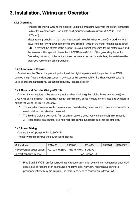
3.4.8 Power Wiring<br />
Connect the AC power to Pin 1, 2 of CN4.<br />
The following table shows the power specifications:<br />
<br />
Motor Model PBM423 PBM603 PBM604 PBM861 PBM862<br />
Power voltage specification AC100V to 230V –15% to +10% 50/60Hz<br />
Current capacity (A rms) See Section 6.4<br />
* Pins 3 and 4 of CN4 are for connecting the regeneration unit, required if a regeneration error ALM<br />
occurs due to reasons such as moving a negative load. Normally, regenerative control is<br />
performed internally by the amplifier, so there is no need to connect an external unit.<br />
3-8