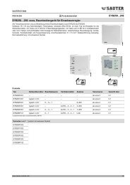
EY-RC416, ecos416: DCC volume flow controller (7194115003)
EY-RC416, ecos416: DCC volume flow controller (7194115003)
EY-RC416, ecos416: DCC volume flow controller (7194115003)

Create successful ePaper yourself
Turn your PDF publications into a flip-book with our unique Google optimized e-Paper software.
<strong>EY</strong>-<strong>RC416</strong><br />
Technical specifications of inputs and outputs<br />
Temperature measurement (NTC, Pt)<br />
The Pt1000 sensors are connected using the two-wire method<br />
between one of the input terminals for a universal input<br />
(UI01…UI04) and an earth terminal. In case of an Ni/NTC/Pt<br />
connection, the inputs do not require calibration and can be used<br />
directly. The connected sensor type and the desired offset input are<br />
chosen in the software.<br />
NTC type 2, 10 k<br />
Range: -40…150 °C<br />
Accuracy: ± 0.5 °C<br />
NTC type 3, 10 k<br />
Range: -40…150 °C<br />
Accuracy: ± 0.5 °C<br />
Circuit Period duration Value<br />
Short-circuit/<br />
override *)<br />
< 5 s<br />
> 5 s<br />
> 15 s<br />
Override = on<br />
Override = off<br />
Input = +199.9<br />
Open - -199.9<br />
PT1000, 1 k<br />
Range: -40…150 °C<br />
Accuracy: ± 1 °C<br />
PT100, 100 k<br />
Range: -40…135 °C<br />
Accuracy: ± 1 °C<br />
Circuit Period duration Value<br />
Short-circuit/<br />
override *)<br />
< 5 s<br />
> 5 s<br />
> 15 s<br />
Override = on<br />
Override = off<br />
Input = +199.9<br />
Open - -199.9<br />
*) If the input is short-circuited, this may be interpreted as an override, i.e. the relevant<br />
control loop is switched from "unoccupied" status to the "occupied/override" operating<br />
mode.<br />
Potentiometer measurement (Pot)<br />
It is possible to use the input in combination with a potentiometer if<br />
a 10 k or 100 k resistance is used. For configuration purposes,<br />
the resistance value can be limited and scaled to any desired value<br />
range in °C. A potentiometer is connected between an input<br />
terminal of a universal input (UI01…UI04) and the associated earth<br />
terminal. The measurement accuracy is ± 0.5%.<br />
Current measurement (I)<br />
The current to be measured is connected to the input terminals of<br />
the universal inputs (UI01…UI04) between UIx and earth. The<br />
signal must be potential-free. In order to use the current input on<br />
the <strong>ecos416</strong> intelligent unitary <strong>controller</strong>, either a supply of current<br />
to the sensor or a parallel input-sensor supply is required. An<br />
external voltage source of 24 V= can be used for this purpose. A<br />
249 resistance must also be connected in parallel with the input.<br />
The input is defined as a 4…20mA input by default.<br />
Voltage measurement (U)<br />
The universal inputs (UI01…UI04) are used to measure voltage.<br />
The voltage input has a range of 0…10 V. The connection is made<br />
to an input and the associated earth terminal. The voltage signal<br />
must be potential-free. The input can be adapted to different ranges<br />
via software. Parameters "min.", "max." or "offset" are available for<br />
this purpose.<br />
Digital inputs (DI)<br />
All universal inputs (UI01…UI04) can be used as digital inputs and<br />
must be connected to earth.<br />
Type of inputs:<br />
Potential-free contacts, connected to earth<br />
Opto-coupler<br />
Transistor (open collector)<br />
Digital information is connected between the input terminals<br />
(UI01…UI04) and earth. The <strong>controller</strong> applies a voltage of approx.<br />
13 V to the terminal. In normal cases (NORMAL) this corresponds<br />
to INACTIVE (bit=0) for an open contact. When a contact is closed<br />
it is ACTIVE (bit=1) and 0 V is applied, whereby the current <strong>flow</strong><br />
equates to approx. 1 mA.<br />
For each input, it is possible to define the "on" and "off" values<br />
individually, as well as the direction of operation (normal or<br />
reverse).<br />
Universal outputs<br />
The universal outputs (UO05 and UO06) can be configured as<br />
voltage outputs, via the software. The output voltage is measured<br />
between the relevant output terminal and an earth terminal (UOx, 5-<br />
6).<br />
Type of output: 0…10 V=<br />
max. 60 mA to earth<br />
Digital output (DO)<br />
Alternatively, the universal outputs (UO05 and UO06) can be<br />
configured as digital outputs. A discrete output signal is issued: 0<br />
V= for OFF and 12 V= for ON.<br />
If a relay is triggered via the universal output, a diode (1N400x<br />
family) must be connected to the connection terminals in parallel.<br />
This protects the output against voltage peaks when the relay cuts<br />
out.<br />
If the universal outputs are configured as PWM outputs, the period<br />
duration can be set between 2 s and 15 min. The period duration<br />
can be set between 0 and 100% of the "on" duration.<br />
Loading capacity of the output: Max. 20 mA at 12 V=<br />
max. load 600 <br />
The output is fitted with a self-resetting fuse.<br />
Maximum power load: 60 mA at 60 °C<br />
100 mA at 100 °C<br />
Triac outputs<br />
4 Triac Max. 1.0 A at 24 V~ per Triac<br />
The jumpers on the <strong>controller</strong> must be changed over in order to use<br />
the internal 24 V supply.<br />
If the power supply is used internally, it is protected with a 3 A fuse.<br />
If the internal power supply is used, an AXT111F202 can be<br />
controlled via the 24 V output in combination with a Triac. For an<br />
application with two AXT111F202s for heating and cooling, it is only<br />
possible to operate one AXT111 in each load case. The internal<br />
heating-cooling sequence prevents the simultaneous operation of<br />
two AXT111F202s.<br />
www.sauter-controls.com 3/5