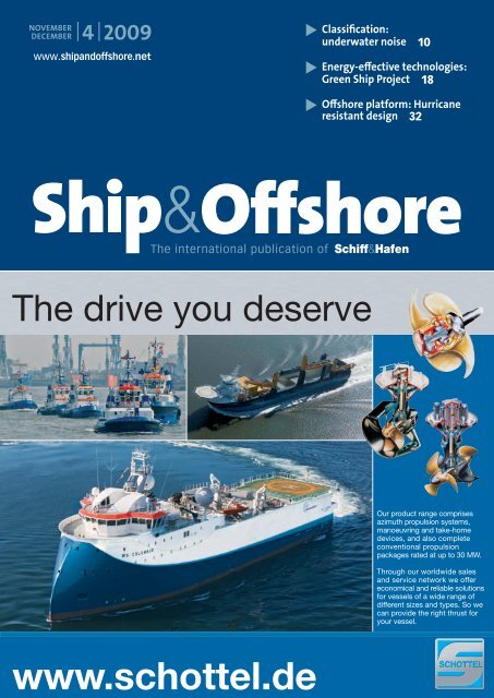
The drive you deserve - Schiff & Hafen
The drive you deserve - Schiff & Hafen
The drive you deserve - Schiff & Hafen

You also want an ePaper? Increase the reach of your titles
YUMPU automatically turns print PDFs into web optimized ePapers that Google loves.
NOVEMBER<br />
DECEMBER | 4 | 2009<br />
www.shipandoffshore.net<br />
Classification:<br />
underwater noise 10<br />
Energy-effective technologies:<br />
Green Ship Project 18<br />
Offshore platform: Hurricane<br />
resistant design 32<br />
<strong>The</strong> international publication of<br />
<strong>The</strong> <strong>drive</strong> <strong>you</strong> <strong>deserve</strong><br />
Our product range comprises<br />
azimuth propulsion systems,<br />
manoeuvring and take-home<br />
devices, and also complete<br />
conventional propulsion<br />
packages rated at up to 30 MW.<br />
Through our worldwide sales<br />
and service network we offer<br />
economical and reliable solutions<br />
for vessels of a wide range of<br />
different sizes and types. So we<br />
can provide the right thrust for<br />
<strong>you</strong>r vessel.<br />
www.schottel.de
supply industry | offshore wind energy<br />
maritime logistics | marine technology<br />
04-06 May 2010<br />
10:00 to 18:00 o’clock<br />
Rostock<br />
www.hansemesse.de<br />
International trade fair<br />
Fair forum<br />
for product presentation<br />
International logistics conference<br />
Offshore conference<br />
Foreign trade day of the<br />
German Association for Small and<br />
Medium-sized Businesses<br />
International contact forum<br />
B2B@BalticFuture<br />
Workshops and seminar on futureoriented<br />
topics of the sector<br />
<strong>The</strong> international trade fair of the maritime industry - BalticFuture - provides<br />
an ideal platform for this innovative sector. <strong>The</strong> key topics of the opening trade<br />
fair, marine supplier industry, offshore wind energy and marine logistics, will<br />
be supplemented by another seminal topic in 2010 - marine technology. Both<br />
trades cooperate intensively regarding interfering technology, development<br />
and implementation opportunities in the economic area Baltic Sea Region.<br />
Here, they get the chance to present themselves on a cross-sector basis.<br />
<strong>The</strong> topic offshore wind energy is of increasing importance for the Baltic Sea<br />
Region. Specialized vessels and professional project services are needed for<br />
the construction and operation of numerous wind farms. <strong>The</strong> BalticFuture<br />
is considered as a node for planners of innovative projects in the Baltic Sea<br />
Region. <strong>The</strong> State Fair Centre of Mecklenburg-Vorpommern with its proximity<br />
to the Baltic Sea and the maritime economy located there ensures optimum<br />
conditions for a sustainable establishment of the conference fair.<br />
Registrations and further information at:<br />
www.baltic-future.com
COMMENT | OFFSHORE<br />
Leon Schulz M.Sc.<br />
Managing Editor<br />
Malta<br />
leon.schulz@dvvmedia.com<br />
Dr.-Ing. Silke Sadowski<br />
Editor in Chief<br />
Hamburg<br />
silke.sadowski@dvvmedia.com<br />
20% steel –<br />
80% technology<br />
It is hardly surprising that many offshore<br />
companies are based around the North Sea. Its harsh<br />
environment has prompted the development of many<br />
technically advanced and innovative solutions. Norway<br />
is one of the thriving countries dedicated to the offshore<br />
industry and is optimistic about the outlook. With the oil<br />
price predicted to rise significantly in the next few years,<br />
the cluster of Norwegian offshore companies hopes for<br />
newbuilding orders to take off from the middle of next<br />
year.<br />
Apart from Norway and other established market players<br />
including Singapore, Korea and more recently Brazil,<br />
China has now also begun to build complex offshore<br />
vessels. In this issue, we describe the two sister ships<br />
Boa Thalassa and Boa Galatea built by Bergen Group Fosen<br />
in Norway (p. 30), as well as the Norwegian Ulstein PX105<br />
design, currently under construction in China (p. 36).<br />
<strong>The</strong> optimistic industry is looking beyond the North Sea to<br />
develop new challenging offshore areas, such as the deep<br />
sea off Brazil, the polar regions and offshore India. <strong>The</strong>re<br />
is a need for new technology, cost-efficient vessels and<br />
environmental awareness.<br />
Offshore survey operators have reported increased<br />
problems working in deep seas due to sound masking<br />
resulting from underwater noise. Furthermore, from the<br />
environmental point of view, mammals are said to be<br />
experiencing difficulties communicating because of an<br />
increasing level of underwater noise. <strong>The</strong> classification<br />
society DNV has taken due note of this problem and is<br />
to publish the first ever notation for underwater noise,<br />
which we describe on p. 10. Another classification societ y,<br />
Germanischer Lloyd, is supporting deep-sea mining with<br />
its new rules for underwater techno logy (p. 34).<br />
In order to meet future environmental requirements,<br />
engine manufacturers and equipment suppliers have<br />
invested intensively in improving and developing<br />
their products. This issue presents innovations such<br />
as new scrubbers to clean SO X<br />
emissions (p. 20) and a<br />
new turbocharger (p. 26). We round up our focus on<br />
propulsion with an interview with Søren H Jensen, vice<br />
president of R&D, Low Speed Engines, on the subject of<br />
the Green Ship of the Future (p. 18).<br />
<strong>The</strong> publishers are proud to announce the following two<br />
decisions taken in the interests of further strengthening our<br />
market position and highlighting our presence in deep-sea<br />
shipping as well as the pioneering offshore market. First,<br />
we will be slightly amending our title to Ship&Offshore,<br />
which better reflects our editorial content, and second,<br />
thanks to the encouragement we have had from the<br />
market, we will be continuing our successful course by<br />
increasing our publication frequency to six issues per year,<br />
thus becoming a bi-monthly.<br />
We trust <strong>you</strong> will continue to appreciate our detailed<br />
c overage of the latest technologies and breakthroughs in<br />
the maritime industry and will enjoy reading this i ssue of<br />
Ship&Offshore.
In Focus<br />
26<br />
Shipbuilding &<br />
Equipment<br />
Maritime environment<br />
10 Notation for underwater noise<br />
Industry news<br />
15 Concept for new-generation car<br />
carrier presented<br />
16 “Weak-but-steady growth”<br />
17 Pioneering technology in the<br />
FellowSHIP project<br />
Green shipping<br />
18 Danish <strong>drive</strong> towards greener<br />
power<br />
Propulsion<br />
20 Scrubbers combat marine<br />
sulphur oxide emissions<br />
22 Calculations on the oil film in<br />
sterntube bearing<br />
Propulsion<br />
Ship propulsion systems, using for instance alternative<br />
fuels or innovative propeller designs, make a major contribution<br />
to improving environmental protection. Fuel consumption<br />
and emissions can be significantly reduced<br />
thanks to new propulsion technology. And with attention<br />
to details, underwater noise can also be minimised.<br />
as from page 20<br />
Classification<br />
Nowadays, classification societies are innovative, pay<br />
attention to every detail and cooperate closely with the<br />
shipbuilding industry as well as deep-sea and offshore<br />
operators. <strong>The</strong>ir great expertise is highly sought after in<br />
the search for new solutions to current requirements,<br />
especially for Arctic und deep-sea offshore operations.<br />
page 10 and 34<br />
Compendium Marine Engineering<br />
Operation – Monitoring – Maintenance<br />
After the great success of the German edition now available in English!<br />
Find out more about this compendium and<br />
order <strong>you</strong>r copy at www.shipandoffshore.net/cme.<br />
4 Ship & Offshore | 2009 | N o 4
CONTENT | NOVEMBER/DECEMBER 2009<br />
30<br />
32<br />
Shipbuilding &<br />
Equipment<br />
Propulsion<br />
26 MAN-Diesel: Latest<br />
product developments<br />
Industry news<br />
28 Laser shaft alignment system<br />
28 Intelligent sensors<br />
28 Cooling pumps to cut energy<br />
consumption<br />
Please visit us at<br />
Marintec China<br />
Stand 2A55<br />
Offshore &<br />
Marine Technology<br />
Offshore oil & gas<br />
30 Electromagnetic sisters serving<br />
the oil & gas industry<br />
32 Hurricane resistant offshore<br />
platform design<br />
Ocean mining<br />
34 Support for deep-sea mining<br />
Newbuildings<br />
36 Flexible Platform Supply Vessels<br />
from China<br />
Renewable marine energy<br />
38 Efficient transition piece installation<br />
for wind farms<br />
Shipping &<br />
Ship Operation<br />
Navigation<br />
48 Satellite Reception of AIS Signals<br />
Industry news<br />
50 Weather warning by satellite<br />
52 KASI Malaysia extends its R&D<br />
capabilities<br />
53 New VSAT antenna<br />
54 Full-service counter-piracy<br />
organisation<br />
Regulars<br />
COMMENT ........................... 3<br />
NEWS & FACTS ................... 6<br />
BUYER‘S GUIDE ................ 39<br />
NEW SHIPS ....................... 58<br />
IMPRINT ............................. 59<br />
ABB Turbocharging.<br />
Don’t take chances.<br />
Original ABB spare parts are <strong>you</strong>r assurance of<br />
the highest quality and precision. For further<br />
information please contact <strong>you</strong>r nearest ABB<br />
Turbocharging service station.<br />
www.abb.com/turbocharging<br />
Ship & Offshore | 2009 | N o 4 5
INDUSTRY | NEWS & FAKTS FACTS<br />
ENC<br />
harmonisation<br />
Cruise ferry Cruise Europa now sails between Italy and Greece<br />
Cruise Europa has taken up service<br />
Minoan Lines | Fincantieri shipyard of Castellammare<br />
di Stabia delivered the Cruise Europa,<br />
third in a series of four innovative cruise ferries<br />
ordered by the Italian shipping group Grimaldi<br />
Group, Napoli, and co-financed by the European<br />
Investment Bank (EIB). For the EIB, the operation<br />
is in line with the policy of investing in the<br />
so-called Motorways of the Sea.<br />
With a length of 225 metres and a width of 31<br />
metres, the Cruise Europa offers 3,000 lane metres<br />
of trucks, trailers, coaches and vans, 250 passenger<br />
cars, and can carry up to 3,000 passengers.<br />
For accomodation the vessel has 413 cabins, of<br />
which there are 18 owner’s suites and 50 junior<br />
suites, in addition to 542 reclining seats. <strong>The</strong><br />
cruise ferry (54,310 gt) sails with a service speed<br />
of 28 knots.<br />
Cruise Europa now serves the daily route Ancona–<br />
Igoumenitsa–Patras v.v of Minoan Lines, a Greek<br />
shipping company and member of the Grimaldi<br />
Group.<br />
Cruise Europa has been set with high standards<br />
similar to those of a cruise ship, both regarding<br />
the public areas and the cabins, as well as for<br />
the entertainment services on board. Two restaurants,<br />
wellness and fitness areas, a supermarket,<br />
two lounges for truck <strong>drive</strong>rs, a conference<br />
centre, shops, internet point, a children’s playground<br />
are among the various amenities offered<br />
onboard.<br />
Navigation | <strong>The</strong> Norwegian<br />
H ydrographic Service (NHS)<br />
and the Directorate of Hydrography<br />
and Navigation (DHN)<br />
of the Brazilian Navy have<br />
signed a bilateral agreement to<br />
formalise the exchange of data,<br />
services, and sharing of expertise<br />
in the field of hydrography<br />
in order to enhance international<br />
maritime safety and protection<br />
of the environment and<br />
to avoid duplication of efforts<br />
between the participants.<br />
As a result of this agreement,<br />
Brazil now becomes a member<br />
of the PRIMAR regional ENC coordinating<br />
centre (RENC) operated<br />
by the NHS and will make<br />
the Brazilian ENCs directly<br />
available through the PRIMAR<br />
ENC service. Currently the ENC<br />
coverage in the Brazilian waters<br />
consists of 94 ENC cells.<br />
This agreement means that<br />
PRIMAR is now able to release<br />
the Brazilian ENCs directly.<br />
Brazil is a key partner for PRI-<br />
MAR and this cooperation will<br />
contribute to Primar’s efforts to<br />
harmonise ENCs globally.<br />
Modernization of the MRCC<br />
New sloshing guidelines<br />
GMDSS | Originally initiated by<br />
the Lithuanian Armed Forces<br />
the modernization of the Maritime<br />
Rescue Control Center<br />
(MRCC) Klaipeda and the infrastructure<br />
of the Lithuanian<br />
part of the Global Maritime<br />
Distress and Safety System<br />
(GMDSS) was finalized.<br />
Lithuanian GMDSS is a national<br />
scale solution and is intended<br />
for use in the interest of<br />
the Lithuanian Armed Forces<br />
<strong>The</strong> Lithuanian MRCC<br />
in Search and Rescue (SAR) operations,<br />
as well as sea border<br />
monitoring. <strong>The</strong> system consists<br />
of one control centre in<br />
Klaipeda and four remote sites<br />
and covers the entire GMDSS<br />
zone of Lithuania.<br />
<strong>The</strong> scope of modernization by<br />
Transas Scandinavia AB included<br />
re-equipping the sites, establishing<br />
of a new control centre<br />
and re-organizing the communication<br />
system. <strong>The</strong> complexity<br />
of the task is characterized<br />
by the need not only to supply<br />
and install new equipment, but<br />
also to relocate and integrate already<br />
existing equipment into<br />
the modernized system. <strong>The</strong><br />
main task was to provide a 24/7<br />
monitoring service using CCTV,<br />
VHF and MF/HF, supporting<br />
both voice as well as DSC communication<br />
channels.<br />
LNG | Lloyd’s Register has<br />
published a new guidance<br />
document for the design of<br />
membrane-technology liquid<br />
natural gas containment systems.<br />
<strong>The</strong> document is aimed at<br />
improving design procedures<br />
with respect to sloshing forces<br />
and has been used as part of<br />
the appraisal process for the<br />
approval of the largest LNG<br />
carriers built to date – the Q-<br />
Max type ships.<br />
<strong>The</strong> principal factors that affect<br />
the behaviour of the fluid<br />
motion are the tank shape, fill<br />
height and the ship’s motions.<br />
As a consequence of this motion,<br />
high impact forces can<br />
occur on the tank boundaries<br />
and this document concerns itself<br />
with the design procedures<br />
necessary to assess the strength<br />
of the tank boundary to these<br />
sloshing impacts.<br />
LNG sloshing is said to be a<br />
very complex issue as there are<br />
many aspects that are difficult<br />
to address explicitly by calculation<br />
or testing. Recently, there<br />
have been several incidents involving<br />
damage to LNG membrane<br />
tanks and the approach<br />
adopted in the document provides<br />
guidance on the processes<br />
necessary to ensure that these<br />
incidents will not recur.<br />
<strong>The</strong> guidance mainly applies<br />
to membrane tank LNG ships<br />
with a barred fill range typical<br />
of the vast majority of membrane<br />
tank LNG ships in current<br />
operation. It can also be<br />
applied for the assessment of<br />
membrane tank LNG ships at<br />
offshore terminals or for LNG<br />
ships with no barred fill range.<br />
6 Ship & Offshore | 2009 | N o 4
Jack-up barge under construction<br />
Gulf Marine Services | A uniquely<br />
designed self-propelled,<br />
self elevating jack-up barge is<br />
currently under construction<br />
in Abu Dhabi, United Arab<br />
Emirates. Gulf Marine Services<br />
(GMS) has developed the GMS<br />
Endurance along with Gusto<br />
MSC.<br />
<strong>The</strong> barge incorporates an operating<br />
water depth of up to<br />
65 metres, accommodation<br />
for 150 persons, deck space<br />
of 1,000m 2 , deck load of<br />
11,350 tonnes, self propelled<br />
DP2 (dynamic positioning),<br />
heavy lift crane capacity of up<br />
to 350 tonnes and four legs for<br />
faster jacking on location.<br />
This new self-propelled jackup<br />
barge design is set to operate<br />
in deeper waters and harsh<br />
environments. <strong>The</strong> design’s<br />
flexibility is said to be suited to<br />
a wider range of opportunities<br />
GMS Endurance, first of two new Gusto 2500X vessels<br />
than existing vessels currently<br />
in the market. Offshore accommodation<br />
& construction,<br />
well intervention & workovers<br />
and drilling completions are<br />
some of the key oil & gas sectors<br />
GMS Endurance has been<br />
targeted to work in.<br />
<strong>The</strong> GMS Endurance is the first<br />
of two new Gusto 2500X vessels<br />
planned by GMS over the<br />
next 12 months.<br />
New Austal high-speed catamaran<br />
Artist‘s impression of the new Austal catamaran<br />
Fast ferry | Austal will build<br />
its biggest catamaran to date<br />
following an order from Denmark’s<br />
Nordic Ferry Services.<br />
<strong>The</strong> order involves the design<br />
and construction of a 113-metre<br />
high-speed vehicle-passenger<br />
ferry, designed to carry<br />
1,400 passengers and 357 cars<br />
between Rønne, on the Danish<br />
island of Bornholm, and Ystad<br />
in south-east Sweden. <strong>The</strong> vessel<br />
will be built at the Austal<br />
facility in Henderson, Western<br />
Australia, and is scheduled for<br />
delivery in May 2011.<br />
<strong>The</strong> new vessel will be powered<br />
by four MAN Diesel 20V<br />
28/33D engines, each delivering<br />
9,100 kW at 1,000 rpm for<br />
100% MCR. Additionally, the<br />
engines have an overload capacity<br />
for a limited time (max.<br />
one hour every six hours)<br />
and can deliver 10,000 kW at<br />
1,032 rpm (110% MCR).<br />
<strong>The</strong> engines will be among<br />
the first to be turbocharged by<br />
MAN Diesel’s new TCA 33 (see<br />
page 26) generation. Due to a<br />
higher pressure rate, the new<br />
turbocharger is said to reach<br />
values of up to 500 kW per cylinder.<br />
<strong>The</strong> new vessel will have<br />
a maximum speed of 40 knots.<br />
Det Norske Veritas will survey<br />
the catamaran’s construction,<br />
ensuring compliance with the<br />
IMO’s HSC code.<br />
With a maximum speed of 40<br />
knots, the new vessel will deliver<br />
an improved transportation<br />
service to Bornholm residents<br />
while also meeting the seasonal<br />
demand generated by holiday-makers.<br />
<strong>The</strong> Rønne-Ystad<br />
route already employs another,<br />
86-metre, Austal catamaran –<br />
Villum Clausen – that entered<br />
service in 2000.<br />
Bornholm has some 43,000 inhabitants<br />
and is visited annually<br />
by about 630,000 tourists.<br />
IN BRIEF<br />
VSAT | <strong>The</strong> new Ku-band<br />
VSAT satellite called Telstar<br />
11N, launched earlier this<br />
year, has taken up service<br />
and its footprint has now<br />
been added to several<br />
satellite service providers.<br />
<strong>The</strong> Atlantic Ocean beam<br />
has meant a significant<br />
improvement for maritime<br />
VSAT communications,<br />
targeting the shipping<br />
industry sailing between<br />
North-America and Europe,<br />
including the Caribbean<br />
and West Africa.<br />
Wärtsilä | An agreement<br />
has been signed whereby<br />
Wärtsilä becomes the<br />
exclusive supplier of bilge<br />
water treatment units to<br />
the Stolt-Nielsen group.<br />
<strong>The</strong> agreement ensures<br />
that newbuildings and<br />
retrofits of existing Stolt<br />
vessels will be fitted with<br />
Wärtsilä Senitec M-series<br />
bilge water treatment<br />
units and Wärtsilä Senitec<br />
BilgeGuard(TM) bilge discharge<br />
monitoring systems.<br />
Cargotec | As part of the<br />
strategy to strengthen its<br />
global support for Mac-<br />
Gregor products, Cargotec<br />
has opened up new service<br />
stations in Zeebrugge<br />
in Belgium, Esbjerg in<br />
Denmark, Liverpool in the<br />
United Kingdom, Cadiz and<br />
Ferrol in Spain, Kaohsiung<br />
in Taiwan, and Balboa in<br />
Panama.<br />
ShipConstructor | In recognition<br />
of today’s challenging<br />
economic times,<br />
the newly released version<br />
of ShipConstructor®<br />
Software (2008 R4.4) is<br />
designed to allow customers<br />
using the level licensing<br />
option to have 50% more<br />
parts per level. <strong>The</strong> increase<br />
is targeted at small<br />
and mid-size clients who<br />
will now be able to design<br />
and model larger vessels<br />
and work on larger projects<br />
with other designers and<br />
shipyards, thus opening<br />
up new revenue streams.<br />
For enterprise level clients,<br />
ShipConstructor still offers<br />
“unlimited” level options.<br />
Ship & Offshore | 2009 | N o 4 7
INDUSTRY | NEWS & FACTS<br />
IN BRIEF<br />
Sale | Odense Steel Shipyard,<br />
Lindø, has entered<br />
into an agreement on the<br />
sale of Loksa Laevatehase<br />
AS (Loksa Shipyard) to a<br />
consortium consisting of<br />
AS Frelok, Crown Solution<br />
OÜ and OÜ Stako Diler, all<br />
Estonia. Lindø Shipyard’s<br />
orders at Loksa Shipyard<br />
will be delivered according<br />
to the original plan.<br />
Lloyd’s Register | A new<br />
global Energy business has<br />
been launched by Lloyd’s<br />
Register Group. This has<br />
been formed by merging<br />
its Oil & Gas and Chemicals<br />
& Power divisions and<br />
underlines Lloyd‘s Register‘s<br />
commitment to become<br />
the leading provider<br />
of independent assurance<br />
services to the energy and<br />
transportation industries.<br />
STX Europe | <strong>The</strong> keel of<br />
a ferry to be built for P&O<br />
Ferries was laid at STX<br />
Europe. When completed<br />
in 2010, this vessel will be<br />
the largest ferry in the English<br />
Channel. <strong>The</strong>re will be<br />
space for more than 180<br />
freight vehicles and, additionally,<br />
up to 195 tourist<br />
vehicles. <strong>The</strong> vessel will be<br />
capable of carrying up to<br />
1,750 passengers.<br />
Thorium LRIT | Collecte<br />
Localisation Satellites (CLS)<br />
and Iridium Communications<br />
Inc. announce that<br />
the U.S. Coast Guard has<br />
type-approved the CLS<br />
Thorium terminal for<br />
Long-Range Identification<br />
and Tracking (LRIT). <strong>The</strong><br />
type approval clears the<br />
way for CLS America to<br />
equip ships sailing under<br />
the U.S. flag to comply with<br />
the international LRIT carriage<br />
requirements.<br />
Hamworthy Krystallon |<br />
Fluid handling systems<br />
supplier Hamworthy has<br />
acquired Krystallon Limited,<br />
the company that<br />
pioneered gas scrubber<br />
development. Hamworthy<br />
Krystallon will be part of<br />
the Inert Gas Systems division.<br />
eInvoice<br />
platform<br />
E-Commerce | <strong>The</strong> French container<br />
shipping company CMA<br />
CGM is piloting INTTRA’s<br />
Web-based eInvoice solution<br />
with select customers in North<br />
America. <strong>The</strong> e-commerce platform<br />
for the ocean freight industry,<br />
INTTRA, enables CMA<br />
CGM and its customers to submit,<br />
receive, review and process<br />
invoices more efficiently and<br />
accurately. CMA CGM’s pilot<br />
program is said to introduce an<br />
industry invoicing platform for<br />
streamlining the submission,<br />
dispute resolution and payment<br />
processes for the ocean shipping<br />
industry. Until now, these processes<br />
included many manual<br />
steps that limited accuracy and<br />
increased operational costs. In<br />
addition, customers have had to<br />
navigate multiple systems across<br />
the industry when doing business<br />
with different carriers.<br />
Delivery of jack up drilling rig<br />
Perro Negro 6 | Jack-up drilling<br />
rig hull L202 or Perro Negro 6,<br />
which was built at Drydocks<br />
World – Graha, was recently<br />
delivered to Saipem (Portugal)<br />
Comercio Maritimo Sociedade<br />
Unipessoal LDA. Drydocks<br />
Perro Negro 6<br />
World – Graha is one of the<br />
three yards located on Batam<br />
Island, Indonesia, and is a part<br />
of Drydocks World-Southeast<br />
Asia Pte. Limited (DDW-SEA),<br />
the Southeast Asian subsidiary<br />
of Drydocks World<br />
Perro Negro 6 is a new generation<br />
MSC CJ46-X100D jack-up<br />
drilling rig, equipped for high<br />
pressure, high temperature<br />
drilling environments, with<br />
the capability of operating at<br />
110 metres water depth and<br />
9,100 metres drilling depth.<br />
<strong>The</strong> design features a large Variable<br />
Deck Load (VDL), extended<br />
deck space and 70 ft and<br />
20 ft X-Y cantilever with an automated<br />
pipe racking system.<br />
As one of the four identical<br />
Jack-Up Drilling Rigs at Drydocks<br />
World – Graha, Perro<br />
Negro 6 is said to conform to<br />
the latest standard of jack-up<br />
drilling rig requirements.<br />
New passenger boarding bridge<br />
Team Passenger Boarding Bridge at the port of Barcelona<br />
Port of Barcelona | Team, Barcelona<br />
based designer and manufacturer<br />
of passenger boarding<br />
bridges for cruise and ferry terminals,<br />
has recently completed<br />
the installation of the first of<br />
two new generation Passenger<br />
Boarding Bridges (PBBs) of the<br />
Creuers Barcelona class. <strong>The</strong>y<br />
are to operate at the A and B<br />
cruise terminals on the Adossado<br />
Quay in the port of Barcelona,<br />
Spain. <strong>The</strong> bridge was successfully<br />
placed into operation<br />
during the inaugural call of the<br />
Carnival Dream to the Mediterranean<br />
cruise port.<br />
Team was contracted by cruise<br />
operator Creuers del Port de<br />
Barcelona S.A. to design, manufacture<br />
and deliver these PBBs,<br />
capable of serving the current<br />
fleet of mega cruise ships like<br />
the Carnival Dream, the Norwegian<br />
Epic and the Oasis Class<br />
vessels of Royal Caribbean,<br />
which are equipped with overhanging<br />
life boats.<br />
Team’s new generation Creuers<br />
Barcelona class PBB can move<br />
along the whole quay and is<br />
able to connect with the various<br />
levels of the cruise ship entry<br />
doors. <strong>The</strong> seaside cabin of<br />
the PBB is equipped with an integrated<br />
hydraulically powered,<br />
telescopic tunnel and docking<br />
ramp that, when attached to<br />
the side of a cruise ship, automatically<br />
follows the vessel’s<br />
movements and will immediately<br />
undock in the event of an<br />
emergency. This PBB provides<br />
6 meters clearance for the overhanging<br />
life boats. <strong>The</strong> clearance<br />
underneath the structure<br />
allows continuous truck and<br />
supply traffic on the quayside.<br />
Team’s Passenger Boarding<br />
Bridges are compliant with all<br />
international safety and security<br />
standards.<br />
8 Ship & Offshore | 2009 | N o 4
Black-water<br />
order<br />
Jets Vacuum | Three times larger<br />
than the old Invincible class,<br />
the new British Royal Navy Aircraft<br />
Carriers HMS Queen Elisabeth<br />
and HMS Prince of Wales<br />
will be the largest warships ever<br />
built in Europe.<br />
Large ships of novel design, the<br />
building of these Carriers offers<br />
formidable challenges for all<br />
parties involved. Jets Vacuum<br />
AS, Hareid, Norway, has been<br />
involved in assisting Babcock<br />
Integrated Technology Limited<br />
with the design of the black<br />
water system and has been<br />
awarded the contract for both<br />
vessels.<br />
As manufacturer of the vacuum<br />
toilet systems for the new UK<br />
Type 45 AAW destroyer, this<br />
equipment contract for the<br />
new aircraft carriers is considered<br />
an important milestone<br />
for Jets Vacuum.<br />
<strong>The</strong> new PSV 09 CD design of STX Norway Offshore<br />
Eco-friendly platform supply vessel<br />
STX Europe | A contract on a<br />
new ”eco-friendly” platform<br />
supply vessel has been signed<br />
between STX Europe and Deep<br />
Sea Supply Navegação Maritima<br />
Ltda in Brazil, a subsidiary<br />
of Deep Sea Supply in Arendal,<br />
Norway. <strong>The</strong> vessel is scheduled<br />
for delivery in 2012, and will be<br />
built at STX Brazil Offshore SA,<br />
part of STX Europe Group.<br />
STX Norway Offshore say they<br />
have been through an extensive<br />
R&D programme over the last<br />
two years and have developed<br />
the new PSV 09 CD design for<br />
good sea keeping performance,<br />
low fuel consumption and<br />
environmental friendly operations.<br />
<strong>The</strong> patent pending<br />
hull design is optimized for<br />
eco-<strong>drive</strong> in all weather conditions,<br />
and is designed with<br />
high focus on reduction of<br />
water resis tance in various conditions.<br />
<strong>The</strong> 87.9m long and<br />
19.0m wide vessel will have a<br />
deadweight of 4,700 t and high<br />
standard accommodation for<br />
26 persons.<br />
<strong>The</strong> vessel is also said to incorporate<br />
tailor-made features in<br />
terms of range, speed, capacity<br />
and cargo flexibility to attend<br />
the challenging requirements<br />
of exploration and production<br />
support operations in the newly<br />
discovered Brazilian “presalt”<br />
oil fields.<br />
EU LRIT DC in production<br />
Long Range Identification | <strong>The</strong><br />
European Union Long Range<br />
Identification and Tracking of<br />
ships Data Centre (EU LRIT<br />
DC) entered in production following<br />
successful developmental<br />
testing.<br />
<strong>The</strong> EU LRIT DC is a combined<br />
effort of the European Commission,<br />
in cooperation with<br />
Member States, through the European<br />
Maritime Safety Agency<br />
(EMSA). <strong>The</strong> Agency is in charge<br />
of the data centre’s technical<br />
development, operation and<br />
maintenance. Currently, it is<br />
estimated that the EU LRIT DC<br />
is the biggest data centre of the<br />
whole international LRIT system.<br />
When all Member States’<br />
ships are phased in by the end<br />
of 2009 it will track around<br />
10,000 ships, which will generate<br />
a minimum of 40,000 position<br />
reports per day.<br />
At present, there are 32 Member<br />
States, EFTA countries and<br />
Overseas Territories participating<br />
in the EU LRIT DC. This<br />
number may increase if other<br />
third countries join in the future.<br />
<strong>The</strong> EU LRIT DC covers an<br />
estimated 20 to 25 percent of<br />
the world fleet subject to LRIT.<br />
In addition to tracking EUflagged<br />
ships, the EU LRIT DC<br />
also provides Member States, on<br />
request, with the LRIT information<br />
of any third country vessel<br />
bound to, or sailing within, EU<br />
waters. So it is possible to track<br />
any ship within a 1,000 nautical<br />
mile zone of a participating<br />
state’s coastline, no matter what<br />
flag the ship is flying.<br />
All maritime authorities of the<br />
Member States, such as those<br />
in charge of Search and Rescue,<br />
Port, Coastal and Flag State responsibilities,<br />
are authorised<br />
users of the system. <strong>The</strong>y can<br />
use the EU LRIT DC to better<br />
track their ships and consult or<br />
request position reports.<br />
To support the work of the<br />
competent maritime authorities<br />
of Member States, EMSA<br />
has set up a permanent monitoring<br />
function (Maritime Support<br />
Services).<br />
Transport of wind turbines on the BBC Konan<br />
Transport of wind turbines<br />
BBC Chartering | 140 wind turbine<br />
towers destined for the<br />
Greater Gabbard Wind Turbine<br />
Park, off the east coast of England,<br />
are in 36 shipments transported<br />
upright on board the<br />
BBC Chartering and Logistic<br />
ship BBC Konan. Fluor, the EPC<br />
responsible for the development<br />
of the wind park, requested<br />
that the nacelles be mounted<br />
with hubs, and the bottom tower<br />
sections be shipped with the<br />
electronics installed prior to the<br />
shipment. This meant that the<br />
tower sections had to be transported<br />
upright on custom-made<br />
transport foundations. Up until<br />
now, this has only been done<br />
on a barge in this way.<br />
Each bottom tower section,<br />
which is on deck in an upright<br />
position, weighs 90 tonnes and<br />
is 25m high. <strong>The</strong> forward position<br />
of the BBC Konan’s bridge<br />
means that the upright towers<br />
do not obstruct the crew’s view.<br />
<strong>The</strong> wind turbine blades measure<br />
52m in length, and the<br />
nacelles with the pre-mounted<br />
hubs are the heaviest pieces,<br />
weighing 177 tonnes each.<br />
Ship & Offshore | 2009 | N o 4 9
SHIPBUILDING & EQUIPMENT | MARITIME ENVIRONMENT<br />
Fig. 1: Certain types of vessels are very sensitive to underwater noise<br />
Notation for underwater noise<br />
ACOUSTICS A low underwater noise level is an essential design feature for operation of certain<br />
ship types as well as when operating in environmentally sensitive areas. On 1 January 2010<br />
the first ever notation on underwater noise will be published by Det Noske Veritas (DNV).<br />
Particularly operators of<br />
offshore survey vessels,<br />
fishery research vessels,<br />
ocean research vessels, seismic<br />
vessels, fishing vessels and<br />
military vessels have noticed increased<br />
problems due to sound<br />
masking resulting from underwater<br />
noise. Such vessels are extremely<br />
sensitive to underwater<br />
noise radiation because a high<br />
noise level will directly interfere<br />
with their operational ability.<br />
Research vessels employ hydroacoustic<br />
sensors to perform their<br />
work tasks, fishing and fishery<br />
research vessels depend on not<br />
frightening away the fish, luxury<br />
yachts and cruise vessels require<br />
a high degree of personal comfort,<br />
military vessels need to operate<br />
undetected and to avoid<br />
triggering of mines. Obviously,<br />
noise control will have to be<br />
given high priority throughout<br />
the design and construction<br />
phases for the vessels mentioned<br />
above.<br />
From an environmental point of<br />
view, the Marine Environmental<br />
Protection Committee (MEPC)<br />
of the International Maritime<br />
Organization (IMO) stated in<br />
July 2009: “<strong>The</strong> committee urges<br />
governments to review their<br />
commercial fleets to identify<br />
the ships that contribute most<br />
to underwater noise pollution”.<br />
At the same time, the International<br />
Fund for Animal Welfare<br />
(IFAW) estimates that the noisiest<br />
10% of ships contribute the<br />
most to the noise problem.<br />
DNV explains that an efficient<br />
noise and vibration control can<br />
be integrated in vessel design<br />
without increasing building<br />
costs significantly and identifies<br />
the propellers usually to be<br />
the most important source for<br />
noise. Radiation of structureborne<br />
noise is identified as the<br />
second most important source.<br />
<strong>The</strong> new optional class notation<br />
by DNV covers a complete set of<br />
criteria and rules for verification<br />
and is intended to ensure operational<br />
capability for four different<br />
types of ships. It is divided<br />
into five sub-notations:<br />
Acoustic (A)<br />
Requirements for vessels using<br />
hydro-acoustic equipment as<br />
an important tool in their operation,<br />
e.g. survey vessels, ocean<br />
research vessels, pipe layers,<br />
diving vessels, various offshore<br />
support vessels etc.<br />
Seismic (S)<br />
Vessels towing heavy streamers<br />
and airguns, hence having<br />
a high demand on propulsion<br />
power.<br />
Fishery (F)<br />
Requirement not to scare away<br />
the catch.<br />
Research (R)<br />
Requirement based on the existing<br />
ICES 209, however with<br />
a low frequency modification.<br />
This is an extremely demanding<br />
criteria requiring “submarine”<br />
type technology.<br />
Environmental (E)<br />
Environmental conscious owners<br />
may demonstrate environmental<br />
compliance through this<br />
“Environment Notation”. This<br />
voluntary class requirement,<br />
which comes in the two levels<br />
called “Transit” and “Passage”, is<br />
to be achieved without increasing<br />
costs beyond that caused<br />
by seeking good engineering<br />
advice with regard to propeller<br />
design and propulsion<br />
10 Ship & Offshore | 2009 | N o 4
vessels often have major differences<br />
with respect to machinery,<br />
arrangement and structure.<br />
Hence, the possibility to use an<br />
analytical approach at the design<br />
stage is valuable. This applies<br />
to the ability to calculate<br />
the propeller’s acoustic source<br />
strength as well as the ability<br />
to calculate the flow of acoustic<br />
energy in a ship hull.<br />
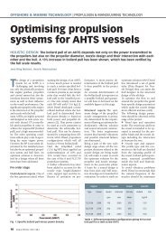
Fig. 2: ICES 209 underwater radiated noise specification at 11 kts<br />
Underwater noise radiated<br />
from commercial vessels operating<br />
in environmentally sensitive<br />
areas is becoming a concern<br />
and recently noise as a<br />
pollutant has received considerable<br />
attention. In dark ocean<br />
waters, marine mammals such<br />
as whales and dolphins rely<br />
on sound to communicate with<br />
each other, locate prey and find<br />
their way over long distances.<br />
All these activities, critical to<br />
their survival, are being interfered<br />
with by the increasing<br />
levels of underwater noise from<br />
ocean-going ships, sonar devices<br />
and seismic exploration.<br />
Sound travels nearly five times<br />
faster in water than in air and<br />
will cover large areas in seconds.<br />
Scientists have become<br />
increasingly aware of this threat<br />
to biodiversity and rate underwater<br />
noise pollution as the<br />
next global treat after climate<br />
change and chemical pollution.<br />
This is a rather diffuse and<br />
not very well understood field.<br />
However, it is already attracting<br />
significant attention from<br />
environmentalists and conservationists<br />
and it is likely that<br />
the field will receive increasing<br />
attention in the years to come.<br />
Examples on strict criteria for<br />
underwater noise radiation are<br />
requirements from the “International<br />
Council for the Exploration<br />
of the Sea” (ICES) cooperative<br />
research report no. 209<br />
(Fig. 2). <strong>The</strong>se are underwater<br />
source levels at a nominal distance<br />
of 1m, and at 11 kts freerunning.<br />
<strong>The</strong>se criteria have<br />
been derived in order to ensure<br />
that fishery research vessels do<br />
not frighten away the fish they<br />
want to count (1 Hz – 1000 Hz)<br />
and that they are not disturbing<br />
their own hydroacoustic instrumentation.<br />
For the ship types identified in<br />
the notation, the underwater<br />
noise control will have to be<br />
given high priority throughout<br />
the design and construction<br />
phase. DNV has developed underwater<br />
noise criteria to assess<br />
the noise level depending on<br />
type and task of vessel, which<br />
now has resulted in the new<br />
notation to be published on<br />
1 January 2010.<br />
Noise pattern<br />
Sound is easily transmitted<br />
in water and is therefore used<br />
for many of the functions that<br />
electromagnetism have in air.<br />
However, background noise<br />
can limit the operational range,<br />
induce errors and even completely<br />
block the acoustical instrumentation,<br />
which is called<br />
“masking”. <strong>The</strong> most significant<br />
noise sources are typically propellers,<br />
diesel engines/gas turbines,<br />
gears, electric propulsion<br />
motors, shafting systems, water<br />
flow along the hull, hydraulics,<br />
ventilation systems, HVAC, exhaust<br />
systems, pumps, auxiliary<br />
machinery and equipment.<br />
<strong>The</strong> noise originates at the<br />
source and is transmitted<br />
through the structure or<br />
through an air or a fluid path.<br />
Structure-borne noise transmission<br />
is the most important<br />
transmission path in the majority<br />
of cases for inboard noise<br />
and plays an important role<br />
also for underwater noise.<br />
Direct waterborne propagation<br />
from propellers is the most important<br />
path for underwater<br />
noise transmission.<br />
A clear understanding of the<br />
individual significance of each<br />
source, transmission path and<br />
radiating mechanism is important<br />
in order to perform meaningful<br />
noise control engineering.<br />
Otherwise a noise control<br />
effort may be unnecessary<br />
expensive, weight and space<br />
intensive or even wasted. <strong>The</strong><br />
necessary knowledge may be<br />
obtained through experience<br />
from measurements. However,<br />
in most cases vessels are built<br />
in small series and even sister<br />
Machinery selection<br />
Based on the acoustic criteria<br />
and source guarantee levels<br />
determined during the early<br />
review the choice of machinery<br />
may be somewhat restricted.<br />
Strict criteria may require that<br />
a diesel electric propulsion<br />
system is used. Diesel electric<br />
propulsion will allow a highly<br />
efficient resilient mounting<br />
system for the diesel generators<br />
without a shaft-line that<br />
could transmit noise from the<br />
diesel engines to a gear or even<br />
generate noise on its own. For<br />
the strictest criteria it may also<br />
be necessary to use a double<br />
resilient mounting system,<br />
which may reduce diesel generator<br />
noise substantially, or<br />
even noise controlled DC electric<br />
propulsion motors may be<br />
required. In some cases, noise<br />
controlled AC motors may be<br />
allowed.<br />
Depending on the criteria, a<br />
noise-reduced gear connected<br />
to a resiliently mounted <br />
Fig. 3: Waterborne noise measured near propeller of a high<br />
power cruise vessel<br />
Ship & Offshore | 2009 | N o 4 11
SHIPBUILDING & EQUIPMENT | MARITIME ENVIRONMENT<br />
diesel engine through a resilient<br />
rubber coupling may be<br />
allowed.<br />
Noise from auxiliary machinery<br />
and equipment, e.g. hydraulic<br />
systems, exhaust systems, steering<br />
gear, compressors, pumps,<br />
fans etc. will also have to be<br />
controlled. Noise from such<br />
systems can usually be controlled<br />
through conventional noise<br />
reducing measures such as resilient<br />
mounts on stiff foundations,<br />
mufflers, enclosures,<br />
resilient compensators and by<br />
locating the sources in locations<br />
well away from critical<br />
surfaces. All these sources need<br />
to be followed up throughout<br />
the project.<br />
Propeller noise<br />
<strong>The</strong> propellers are often the<br />
most important noise source<br />
for a ship. This applies to<br />
waterborne noise radiation<br />
for research, fishing and military<br />
vessels as well as for interior<br />
noise levels in the aftship<br />
of yachts and cruise vessels.<br />
Hence, it is vital to be able to<br />
calculate propeller noise and to<br />
possess knowledge on design<br />
of low noise propellers when<br />
needed.<br />
<strong>The</strong> knowledge in the industry<br />
on propeller excitation caused<br />
by transient cavitation at the<br />
propeller blades has increased<br />
during the last years. <strong>The</strong> magnitude<br />
of the blade pass frequency<br />
component of the hull pressures<br />
has gradually decreased over the<br />
last couple of decades.<br />
However, the broad-band pressure<br />
generated by the propellers,<br />
which is the most important<br />
noise mechanism, still<br />
causes problems. An illustrative<br />
example of measured waterborne<br />
noise near a propeller<br />
of a cruise vessel is shown in<br />
fig. 3. For this vessel, clearly the<br />
broad-band cavitation noise is<br />
stronger than the noise at the<br />
blade passing frequency.<br />
<strong>The</strong> propellers excite the hull<br />
in different ways. <strong>The</strong> low frequency<br />
excitation will be felt<br />
as vibrations and the higher<br />
frequencies perceived as noise<br />
inside the vessel. Both frequency<br />
regimes will be emitted into<br />
the water.<br />
It is possible to reduce or even<br />
avoid such problems, by applying<br />
novel knowledge on broadband<br />
pressure field generated<br />
by the propeller in the design<br />
of new propellers.<br />
<strong>The</strong> excitation from the propellers<br />
can be divided into different<br />
groups:<br />
Fluctuating forces and moments<br />
transferred from the<br />
propellers to the shaft system.<br />
This type of excitation consists<br />
mainly of 1st order blade frequency<br />
components and contributes<br />
to the vibration of the<br />
vessel, but not to the noise.<br />
Pressure fluctuations transferred<br />
through the water from<br />
the propellers to the hull or<br />
to a far field underwater location.<br />
This pressure fluctuations<br />
generated by the propellers can<br />
again be divided into three<br />
main groups: Pressure variations<br />
generated by propellers<br />
without cavitation, pressure<br />
generated by transient cavitation<br />
on the propeller blades<br />
and, finally and most importantly,<br />
the pressures generated<br />
by cavitating vortices.<br />
Pressure field generated by<br />
cavitating vortices contains a<br />
continuous pressure spectrum<br />
and is responsible for much of<br />
the audible inboard noise from<br />
the propellers as well as being<br />
an important source of underwater<br />
noise. Pressure field from<br />
strong vortices also contains<br />
pressures of low frequencies<br />
that create vibration. Vortices<br />
created by fixed pitch propellers<br />
as well as by controllable<br />
pitch propellers at the design<br />
pitch are tip vortices. <strong>The</strong> tip<br />
vortices and the pressure field<br />
generated by them, increase<br />
gradually with the propeller<br />
RPM. However, for controllable<br />
pitch propellers vortices from<br />
the pressure side of the blades<br />
are generated at reduced pitch.<br />
Hence, the noise may be more<br />
severe at reduced ship speed<br />
than at full speed if controllable<br />
pitch propellers are used.<br />
DNV has developed a method<br />
to predict the broad-band pressure<br />
field generated by the cavitating<br />
tip vortices, the so-called<br />
Tip Vortex Index method (TVI<br />
method).<br />
<strong>The</strong> magnitude and frequency<br />
content of the measured pressure<br />
depend strongly on the<br />
transducer position on the<br />
Fig. 4: Reduction in propeller noise through design optimisation<br />
hull since they are in the “near<br />
field”. <strong>The</strong>refore, it is difficult<br />
to establish the magnitude of<br />
the excitation based on a few<br />
hull pressure recordings. It is<br />
common in hydro-acoustics<br />
to describe a noise sources as<br />
an equivalent point sources.<br />
This can also be applied for<br />
the propeller. <strong>The</strong> advantage<br />
of considering the propeller as<br />
a hydro-acoustic noise source<br />
is that the propeller excitation<br />
can be evaluated alone without<br />
taking into consideration the<br />
clearances between the propeller<br />
and the hull.<br />
Propeller design<br />
Detailed propeller blade design<br />
can be used to reduce propeller<br />
noise. Basically a large diameter<br />
propeller with a blade<br />
design which is unloaded towards<br />
the tips will be advantageous<br />
in many cases. However,<br />
the blade design will often be<br />
a compromise between noise<br />
and efficiency. For noise sensitive<br />
vessels a moderate loss in<br />
efficiency can normally be accepted<br />
if a significant noise reduction<br />
can be achieved. Fig. 4<br />
shows an example from a noise<br />
optimisation process during<br />
propeller design.<br />
Obviously, the propeller wake<br />
influences propeller noise generation<br />
significantly. <strong>The</strong> hull<br />
lines and orientation of shaft<br />
brackets are important for the<br />
flow to the propellers and so is<br />
the propeller turning direction.<br />
<strong>The</strong> reason is the interaction of<br />
the axial and tangential wake<br />
components.<br />
<strong>The</strong> importance of propeller<br />
– hull clearances is exaggerated<br />
in most cases, due to the<br />
focus on maximum hull pressures<br />
rather than on the excitation<br />
forces. It is usually better<br />
to have a large lightly loaded<br />
propeller and small clearances<br />
than a small diameter propeller<br />
and large clearances.<br />
Fixed pitch propellers behave<br />
predictably with respect to development<br />
of noise and broadband<br />
vibration with ship speed.<br />
<strong>The</strong> propeller RPM is about<br />
proportional to the ship speed<br />
and therefore the propellers<br />
will operate at nearly the same<br />
hydrodynamic angle of attack<br />
at any ship speed. Consequently,<br />
the noise and broad-band<br />
vibration will increase gradually<br />
with the power.<br />
Controllable pitch propellers<br />
behave as fixed pitch propellers<br />
at design pitch. However,<br />
at reduced pitch and high<br />
RPM most propellers will<br />
start to generate cavitation on<br />
the pressure side. Such cavitating<br />
vortices can be as noisy<br />
as the tip vortices at full pitch.<br />
If shaft generators requiring<br />
constant RPM are coupled<br />
to the engines, the propellers<br />
can be very noisy over a broad<br />
speed range. If the propeller<br />
speed is gradually reduced<br />
with power, a controllable<br />
pitch propeller does not need<br />
to be noisier than a fixed pitch<br />
propeller.<br />
12 Ship & Offshore | 2009 | N o 4
Software for IACS<br />
Common Structural Rules<br />
ABS/LR | ABS and Lloyd’s<br />
Register have agreed to use<br />
a common software for the<br />
assessment of scantlings of<br />
bulk carriers and oil tankers<br />
designed to comply with the<br />
new IACS Common Structural<br />
Rules. <strong>The</strong> new common<br />
software draws on the existing<br />
applications of both societies<br />
with the Lloyd’s Register<br />
approach being used for the<br />
initial scantling evaluation<br />
(CSR Stage 1) and the ABS approach<br />
being used for the finite<br />
element assessment (CSR<br />
Stage 2).<br />
<strong>The</strong> announcement comes after<br />
two years of detailed work<br />
by dedicated teams from both<br />
classification societies to identify<br />
and implement the best<br />
amalgam of the strengths of<br />
both societies’ existing CSR<br />
software.<br />
ABS says that although shipyards,<br />
designers and shipowners<br />
have welcomed the adoption<br />
of the IACS Common<br />
Structural Rules, they have<br />
made repeated requests for a<br />
similar approach to be taken<br />
with the software needed for<br />
the application of the Rules.<br />
Richard Sadler, Chief Executive<br />
of Lloyd’s Register, says they<br />
have moved from ten sets of<br />
Rules for tankers and another<br />
ten sets for bulk carriers to a<br />
single standard for each ship<br />
type. Yet, the classification societies<br />
have developed multiple<br />
software programs for each<br />
of the new Rules, which he says<br />
dilutes the intent of the Rules<br />
and introduces an unnecessary<br />
element of confusion for the<br />
designers and shipyards.<br />
Testing of the new joint software<br />
is being finalised and<br />
design review engineers from<br />
both societies are scheduled<br />
to begin intensive training on<br />
its application. Once this process<br />
has been concluded, each<br />
of the societies will withdraw<br />
their existing CSR software<br />
and all new designs presented<br />
to either society will be evaluated<br />
using the new common<br />
software.<br />
In the interests of promoting<br />
technical consistency and<br />
maritime safety, the two societies<br />
have also announced that,<br />
once the exhaustive testing<br />
of the new software has been<br />
completed, it will be made<br />
available to other IACS members.<br />
<strong>The</strong> IACS Common Structural<br />
Rules for Tankers and Bulk<br />
Carriers were unanimously<br />
adopted by the ten member<br />
societies in December 2005.<br />
<strong>The</strong>y became effective for<br />
vessels contracted on or after<br />
1 April 2006. <strong>The</strong>y apply to all<br />
double hull tankers of 150m<br />
in length and above and to<br />
single and double side skin<br />
bulk carriers of 90m in length<br />
and upward, other than ore<br />
carriers.<br />
First fishing trawler with SkySails<br />
ALTERNATIVE PROPULSION |<br />
Parlevliet & Van der Plas B.V.,<br />
one of Europe’s biggest fishing<br />
companies, has signed a<br />
purchase agreement for the<br />
world’s first towing-kite wind<br />
propulsion system to be installed<br />
on a fishing trawler.<br />
SkySails propulsion is scheduled<br />
to be placed in operation<br />
early next year aboard<br />
the ROS-171 Maartje <strong>The</strong>adora<br />
fishing trawler. <strong>The</strong> fishing<br />
company says they are looking<br />
forward to significant fuel<br />
savings by using the SkySails-<br />
System, particularly during<br />
those extended transfer runs<br />
to the African coast and in the<br />
South Pacific, as well as to the<br />
potential savings during actual<br />
fishing operations. At the<br />
same time, this enables Parlevliet<br />
& Van der Plas to reduce a<br />
considerable amounts of CO 2<br />
emissions as a contribution to<br />
safeguarding the climate.<br />
At 141 meters in length, the<br />
Maartje <strong>The</strong>adora is Germany’s<br />
largest fishing vessel and<br />
is operated by the Sassnitzbased<br />
Westbank Hochseefischerei<br />
GmbH, a member of<br />
the Parlevliet & Van der Plas<br />
Group. <strong>The</strong> ship has two MaK<br />
main engines that produce a<br />
total of 8,640 kW of power.<br />
<strong>The</strong> vessel will be fitted with<br />
a 160m² SkySails propulsion<br />
system like those already in<br />
use on cargo ships. Parlevliet<br />
& Van der Plas and the systems<br />
manufacturer SkySails will be<br />
evaluating if and in what way<br />
the wind propulsion system<br />
needs to be modified for use<br />
on fishing vessels on board<br />
the Maartje <strong>The</strong>adora as part<br />
of a pilot project funded by<br />
the European Fisheries Fund<br />
(EFF) and the German state<br />
of Mecklenburg-Western Pomerania.<br />
SkySails propulsion previously<br />
underwent pilot testing<br />
for a year and a half aboard<br />
the cargo ships Beluga Sky-<br />
Sails, owned by the Beluga<br />
An impression on how SkySails would fit on Maartje <strong>The</strong>adora<br />
Group, and the Michael A. of<br />
the Wessels Shipping Company.<br />
Despite its unprecedented<br />
physical properties, the system<br />
is claimed to produce<br />
between 5 and 25 times more<br />
power per square meter than<br />
conventional sail propulsion.<br />
Even a 160m² SkySails is said<br />
to generate a tractive force of<br />
8 metric tons, which is comparable<br />
to the thrust of an<br />
Airbus A318 engine.<br />
SkySails is currently also fitting<br />
its innovative towing-kite<br />
propulsion system onto a series<br />
of three new cargo ships<br />
belonging to the Wessels<br />
Shipping Company of Haren<br />
an der Ems.<br />
Ship & Offshore | 2009 | N o 4 13
SHIPBUILDING & EQUIPMENT | INDUSTRY NEWS<br />
Caspian ice-breaking tugs<br />
CLASSIFICATION | Bureau<br />
Veritas has been chosen to<br />
class two different series of icebreaking<br />
tugs for service in the<br />
Caspian Sea.<br />
<strong>The</strong> first series is for three plus<br />
two 66m ice-breaking and<br />
ice management tugs with<br />
50 tonnes bollard pull (BP)<br />
and Ice Class IA Super Special<br />
Service – North Caspian Sea<br />
Icebreaker with ice breaking<br />
capability up to 0.6m level ice<br />
thickness. Designed by Aker<br />
Arctic, they will be built at the<br />
STX RO Offshore Braila yard<br />
in Romania for the Caspian<br />
Offshore Construction group<br />
project in the North Caspian<br />
Kashgan oil field.<br />
<strong>The</strong> design has been made for<br />
the shallow waters of the North<br />
Caspian Sea, where the vessels<br />
will break level ice and can<br />
operate year round in ice conditions<br />
up to 1m thickness. In<br />
addition to towing and pushing<br />
barges in open water and in ice<br />
conditions, they will be capable<br />
of ice management operations<br />
in astern working mode, clearing<br />
ice rubble. <strong>The</strong> vessels will<br />
be equipped for undertaking<br />
firefighting, rescue and evacuation<br />
tasks and have deck cargo<br />
capability for supply functions.<br />
<strong>The</strong> second series is currently<br />
out to tender and is for shallow<br />
Ice tug tests for the Caspian Sea<br />
draft ice-breaking Anchor Handling<br />
Tug Supply (AHTS) vessels<br />
to be built for Silverburn<br />
Shipping. Designed by <strong>The</strong><br />
Netherlands-based Offshore<br />
Ship Designers these vessels<br />
will be able to work in 0,7m<br />
of ice. <strong>The</strong>y have a significant<br />
load carrying capability on a<br />
shallow draft and provide a<br />
minimum 45 tonnes BP. Model<br />
tests at Aker Arctic showed the<br />
hull form can perform in ice to<br />
Finnish/Swedish Ice Class 1A<br />
Super standards. Main dimensions<br />
are LOA 49.6m, beam<br />
16.5m, seagoing draft 3.5m,<br />
shallow draft 2.5m.<br />
Ice-class FSO<br />
YURI KORCHAGIN | <strong>The</strong> first<br />
ice-class floating storage and<br />
offloading system (FSO) to be<br />
completed at a Caspian Sea<br />
shipyard and deployed for<br />
service in the Caspian Sea, the<br />
Yuri Korchagin, is destined for<br />
the Yuri Korchagin Field in the<br />
Russian sector of the Caspian<br />
Sea where it will operate for<br />
Lukoil.<br />
<strong>The</strong> FSO hull was constructed<br />
in two longitudinal halves by<br />
Keppel Singmarine in Singapore<br />
and was towed through<br />
the Volga-Don River Canal and<br />
assembled at Keppel Fels’ Caspian<br />
Shipyard Company (CSC)<br />
in Baku, Azerbaijan. According<br />
to classification society ABS, the<br />
size limitation of the Canal dictated<br />
that the unit be constructed<br />
in two modules for import<br />
into the region. <strong>The</strong> two hull<br />
sections were aligned and joined<br />
in drydock at the Caspian shipyard.<br />
<strong>The</strong> helideck and accommodation<br />
quarters, as well as<br />
other equipment, were loaded<br />
alongside the hull sections and<br />
also assembled at CSC.<br />
<strong>The</strong> unit has been built to the<br />
ABS class notation +A1, Floating<br />
Storage and Offloading System,<br />
Ice Class C0, +AMCCU,<br />
FL(20). Yuri Korchagin is 132.8m<br />
in length, 32m in width and<br />
has a depth of 15.7m. It has a<br />
fatigue life of 20 years and is<br />
dual classed with RS. <strong>The</strong> FSO<br />
can withstand ice conditions of<br />
minus 20 degrees Celsius and<br />
ice thickness of 0.6m.<br />
Russia’s Lukoil is targeting to<br />
start commercial oil production<br />
before long. When in operation,<br />
it will be the largest<br />
FSO in the Caspian Sea.<br />
BOOK REVIEW<br />
Compendium Marine Engineering:<br />
Operation – Monitoring – Maintenance Following the German<br />
edition “Handbuch <strong>Schiff</strong>sbetriebstechnik” in 2006,<br />
now the English version is available. <strong>The</strong> technical book is<br />
mainly directed towards marine engineers, principally within<br />
the marine industry. It is also addressed to ship operators,<br />
superintendents and surveyors, but also to those in training<br />
and research institutes as well as designers and consultants.<br />
Compendium Marine Engineering represents a compilation<br />
of marine engineering experience. It is based on the research<br />
of scientists and the reports of many field engineers<br />
all over the world. within the field of ship’s and engine operation<br />
subjects like cargo handling equipment, air-conditioning<br />
technology incl problems with reefer containers, safety<br />
equipment as well as envirionmental<br />
matters, maintenance and regulations<br />
are dealt with.<br />
Compendium Marine Engineering<br />
Hansheinrich Meier-Peter, Frank<br />
Bernhardt<br />
Seehafen Verlag<br />
1100 pages, hardcover<br />
978-3-87743-822-0<br />
98,- Euro plus postage<br />
14 Ship & Offshore | 2009 | N o 4
Concept for new-generation<br />
car carrier presented<br />
ISHIN-I CAR CARRIER | Mitsui<br />
O.S.K. Lines, Ltd. (MOL Lines)<br />
has developed a new type of<br />
car vessels. <strong>The</strong>y are said to be<br />
technically practical in the near<br />
future by building on and refining<br />
technologies it has already<br />
developed and adopted.<br />
<strong>The</strong> first of its next-generation,<br />
environment-friendly<br />
vesse l concepts is the car carrier<br />
ISHIN-I, which stands for<br />
“Innovations in Sustainability<br />
backed by Historically proven,<br />
INtegrated technologies.”<br />
ISHIN-I is said to have two main<br />
features: the goal is to achieve<br />
zero CO 2<br />
-emissions while in<br />
port, and during loading and<br />
unloading, mainly by adopting<br />
large-capacity solar-power panels<br />
and rechargeable batteries.<br />
While sailing, the CO 2<br />
-emission<br />
is to be reduced by 41% in<br />
comparison (per unit) to conventional<br />
vessels (PCTC with a<br />
capacity of 6,400 standard passenger<br />
cars). This is achieved<br />
by adopting multiple new technologies.<br />
When needs for larger<br />
vessels arise in the future, CO 2<br />
emissions is claimed to be reduced<br />
by as much as 50% on<br />
that assumption.<br />
To pur the two main features<br />
into practice, the concept is<br />
based on the following main<br />
technologies:<br />
Use of renewable energy<br />
Solar panels partly already<br />
adopted on the MOL-car-carriers<br />
Euphony Ace and Swift Ace will<br />
be used on the ISHIN-I. Zero<br />
emissions while in port and during<br />
loading and unloading is to<br />
be achieved by installing largecapacity<br />
rechargeable batteries<br />
(lithium ion) and combining<br />
them with an electric propulsion<br />
system.<br />
Optimization of propulsion<br />
efficiency<br />
<strong>The</strong> main-diesel engine is combined<br />
with an electric propulsion<br />
system. A pair of contrarotating<br />
propellers are installed<br />
facing each other at the stern.<br />
<strong>The</strong> new ISHIN-I concept minimising CO 2<br />
emissions<br />
<strong>The</strong> propellers share the burden<br />
of powering the ship and spin<br />
in opposite directions, allowing<br />
the rear propeller to absorb<br />
the rotation energy of the front<br />
propeller.<br />
As a result, the system is to increase<br />
efficiency. Furthermore,<br />
the advanced model of the<br />
MOL-developed Advanced Propeller<br />
Boss Cap Fins (PBCF) will<br />
be used. This device has been<br />
adopted on more than 1,700<br />
vessels all over the world.<br />
Wind resistance design<br />
A special design was developed<br />
by MOL, futher refining the<br />
hull shape to reduce wind pressure<br />
from the bow and sides.<br />
<strong>The</strong> shape of the stern also<br />
smoothes the flow of the wind.<br />
Reduction of friction drag<br />
Next-generation vessels will be<br />
covered with ultra-low friction<br />
ship bottom paint. By trapping<br />
water on the coated surface,<br />
this paint is said to eliminate<br />
friction drag caused by minute<br />
patterned indentations formed<br />
on conventionally painted surfaces.<br />
Optimum voyage support system<br />
<strong>The</strong> optimum voyage support<br />
system relies on the latest marine<br />
weather information while<br />
monitoring voyage conditions,<br />
and searches for the shortest,<br />
most fuel-efficient routes while<br />
taking into account the differences<br />
in various types and hull<br />
forms of ships.<br />
Optimization of engine system<br />
Fuel supply to the engine is<br />
electronically controlled, and<br />
the vessel operates with the<br />
optimum fuel supply. <strong>The</strong>rmal<br />
energy conventionally lost with<br />
exhaust gas will be efficiently<br />
recovered for reuse.<br />
Optimization of hull design<br />
<strong>The</strong> hull form has been improved,<br />
in pursuit of further<br />
improvements in fuel efficiency.<br />
Larger hull compatible with<br />
new Panama Canal<br />
When needs for larger vessels<br />
arise, the adoption of<br />
twin-shaft propellers shall allow<br />
greater improvement in<br />
propulsion performance and<br />
fuel efficiency.<br />
Ship & Offshore | 2009 | N o 4 15
SHIPBUILDING & EQUIPMENT | INDUSTRY NEWS<br />
“Weak-but-steady growth”<br />
<strong>The</strong> sixth edition of Inmex<br />
India in Mumbai<br />
Interest<br />
in India<br />
INMEX INDIA | 450 exhibitors<br />
from 39 countries are<br />
reported to have exhibited on<br />
the recent Inmex India exhibition<br />
at the Bombay Exhibition<br />
Centre held on 24–26<br />
September. Some 5,000 visitors<br />
attended the show and<br />
early reports show a high<br />
level of satisfaction. Over<br />
93% of the exhibitors stated<br />
that they wished to exhibit at<br />
Inmex India 2011 with both<br />
Indian and international exhibitors<br />
reporting a great deal<br />
of business activity.<br />
This international event hosted<br />
country pavilions for Germany,<br />
Korea, China, Singapore<br />
and Holland. <strong>The</strong> B-2-B<br />
Forum consisting of round<br />
table sessions and one-toone<br />
meetings under the<br />
motto “Transforming India<br />
into a maritime hub by the<br />
next decade” attracted more<br />
than 500 businessmen and<br />
captains. Senior level professional<br />
attendees debated<br />
and strategized to define the<br />
future of the maritime landscape.<br />
Inmex India 2011 will be<br />
held from 29 September to<br />
1 Octo ber 2011 in Mumbai.<br />
OIL AND GAS TANKER | <strong>The</strong><br />
world fleet of oil, chemical and<br />
gas tankers is predicted to continue<br />
to grow over the next five<br />
years, although at a much more<br />
sluggish rate than the previous<br />
five years, according to a Shipbuilding<br />
Market Report issued<br />
this month by Lloyd’s Register<br />
– Fairplay (LR Fairplay).<br />
<strong>The</strong> oil tanker fleet, which currently<br />
stands at 7,516 ships, is<br />
expected to grow by 1.9 percent<br />
per year over the next five years<br />
in terms of the number of ships.<br />
Deadweight ton (dwt) capacity<br />
will rise by 5.7 percent annually<br />
over the same period, reflecting<br />
a movement toward larger<br />
ships. New shipbuilding orders<br />
for oil tankers will amount to<br />
76 million dwt through the<br />
end of 2013, a 60 percent decrease<br />
from the shipbuilding<br />
binge of the last five years.<br />
LR Fairplay says that the record<br />
number of shipbuilding orders<br />
in 2006 means that a large<br />
number of ships are being delivered<br />
to owners this year. <strong>The</strong><br />
gap between supply and demand<br />
will therefore continue<br />
to grow, which is likely to generate<br />
an increasing fleet of idle<br />
vessels.<br />
<strong>The</strong> chronic overcapacity in<br />
tanker tonnage will accelerate<br />
the scrapping of older ships.<br />
Removals of oil tankers through<br />
year-end 2013 will amount to<br />
50 million dwt, which is up<br />
by 10 percent compared to the<br />
previous five years. While relatively<br />
few new orders are being<br />
placed for tanker tonnage, the<br />
LR Fairplay report predicts new<br />
orders to amount to 76 million<br />
dwt over the next five years – a<br />
60 percent decrease from the<br />
last five years.<br />
<strong>The</strong> prospect for chemical tankers<br />
is somewhat rosier, according<br />
to the LR Fairplay study.<br />
<strong>The</strong> current fleet of 4,619 ships<br />
will grow by 8 percent annually<br />
over the next five years.<br />
<strong>The</strong> growth curve for the liquefied<br />
petroleum gas (LPG)<br />
sector will also flatten. <strong>The</strong><br />
LPG fleet currently stands at<br />
1,166 ships with a total capacity<br />
of 18.7 million cubic meters<br />
(m³). <strong>The</strong> fleet grew by 13 percent<br />
last year, but the rate will<br />
slow to 4.6 percent this year. In<br />
2010 and 2011, the rate will fall<br />
to 1.6 percent and 0.9 percent,<br />
respectively. New tonnage deliveries<br />
and expected delays in<br />
LPG production will result in a<br />
<strong>The</strong> tanker fleet will continue to grow, says LR Fairplay<br />
rise in recycling of older ships<br />
and use of idle ships for floating<br />
storage.<br />
<strong>The</strong> relatively small fleet of<br />
321 specialized liquefied natural<br />
gas (LNG) carriers faces<br />
grim prospects with the current<br />
utilization rates of 60–65<br />
percent falling even further as<br />
increasing numbers of new<br />
ships are delivered ahead<br />
of the projects they were intended<br />
for. <strong>The</strong> oversupply is<br />
likely to bottom out next year<br />
as the delayed liquefaction<br />
projects come on stream, and<br />
the fleet will grow by an average<br />
of 3.8 percent annually<br />
through 2011. Ordering for<br />
the 2009–2013 period is forecast<br />
at 174 new LNG carriers,<br />
10 percent lower than the last<br />
five years.<br />
<strong>The</strong> LR Fairplay report notes<br />
that South Korea continues to<br />
dominate the world tanker production<br />
market with 51 percent<br />
of the tonnage on order. China<br />
comes in a distant second<br />
with 25 percent, and Japan is<br />
in third place with 16 percent.<br />
If measured in the number of<br />
ships, however, South Korea’s<br />
market share is just 35 percent,<br />
with China at 28 percent.<br />
16 Ship & Offshore | 2009 | N o 4
Pioneering technology in<br />
the FellowSHIP project<br />
FUEL CELLS | <strong>The</strong> Fellow-<br />
SHIP project, supported by the<br />
Norwegian Research Council<br />
(Oslo), Innovation Norway<br />
(Oslo), and the German Federal<br />
Ministry of Economics and<br />
Technology (Berlin), is a joint<br />
industry research and development<br />
project managed by the<br />
classification society Det Norske<br />
Veritas (Oslo).<br />
It aims to develop and demonstrate<br />
hybrid fuel cell<br />
power packs, especially suited<br />
for marine and offshore use.<br />
<strong>The</strong> equipment has been installed<br />
onboard the platform<br />
supply vessel Viking Lady for<br />
extensive sea tests. <strong>The</strong> power<br />
pack will be used as an auxililiary<br />
power source onboard the<br />
ship, which is owned by Eidesvik<br />
Offshore, Norway.<br />
Wärtsilä (Helsiniki), involved<br />
in fuel cell technology since<br />
the mid 1990’s has been assigned<br />
overall responsibility<br />
for systems integration in the<br />
FellowSHIP project. Wärtsilä’s<br />
equipment is being used to<br />
integrate and create synergies<br />
between leading marine technology<br />
and fuel cell technology.<br />
<strong>The</strong> Viking Lady has been designed<br />
by Wärtsilä Ship Design,<br />
and its main engines and<br />
power <strong>drive</strong>s have also been<br />
Viking Lady, designed by Wärtsilä<br />
supplied by Wärtsilä. Wärtsilä’s<br />
electrical & automation business<br />
unit in Norway has custom<br />
developed the power electronics<br />
needed to connect the<br />
fuel cell to the ship’s electrical<br />
network.<br />
<strong>The</strong> 320 kW fuel cell, produced<br />
by MTU Onsite Energy<br />
GmbH (Friedrichshafen), a<br />
member of the German Tognum<br />
Group, has been integrated<br />
together with Wärtsilä’s<br />
technology, and tested. During<br />
this land testing, all operational<br />
modes, shut down<br />
conditions, and dynamical<br />
behaviour have been tested<br />
and verified in accordance<br />
with the specifications.<br />
<strong>The</strong> fuel cell technology is designed<br />
to increase efficiency<br />
and leads to a considerable reduction<br />
in emissions. Fuel cell<br />
technology of this power size<br />
has never before been installed<br />
in merchant vessels, and the<br />
highly innovative project is<br />
said to be unique on a world<br />
scale.<br />
Supply<br />
packages<br />
SHIPS SERVICE | Wilhelmsen<br />
Ships Service is implementing<br />
an initiative that recognises<br />
the high level of newbuildings<br />
completing in 2009, known<br />
as “Solutions for a Lifetime”.<br />
It focuses on the importance<br />
of recognising the continued<br />
requirements of newbuildings<br />
to be supplied with the<br />
highest quality of products<br />
and services from the earliest<br />
construction stages through<br />
the life of the ship until scrapping.<br />
<strong>The</strong> initiative uses a unique<br />
product selector tool, which<br />
enables newbuilding managers<br />
to compile a tailor made<br />
Initial Supply Package within<br />
the total Wilhelmsen Ships<br />
Service offer. Finding the right<br />
match of products with its accessories<br />
and consumables as<br />
well as compliance with rules<br />
and regulations is said to be<br />
taken care of.<br />
According to updated figures<br />
from maritime classification<br />
society Lloyd’s Register the<br />
number of completed newbuildings<br />
in 2009 is expected<br />
to be on a similar level to the<br />
2008 figure. Wilhelmsen Ships<br />
Service is targeting the Initial<br />
Supply order for each vessel,<br />
and the company’s service<br />
skills is also said to ensure<br />
ongoing maintenance of after<br />
sales contracts.<br />
MTU- Direct Dealer and Service Station / ZF-Spare Parts and Service<br />
Diesel Engines Gearboxes Gensets with Diesel Engines<br />
<br />
<br />
Ship & Offshore | 2009 | N o 4 17
SHIPBUILDING & EQUIPMENT | MARITIME ENVIRONMENT<br />
Danish <strong>drive</strong><br />
towards<br />
greener power<br />
GREEN SHIPPING MAN Diesel<br />
and AP Møller-Mærsk joined<br />
forces last year in a partnership<br />
with other Danish companies –<br />
including Force Technology,<br />
Aalborg Industries and Hempel –<br />
in a Green Ship of the Future<br />
project. <strong>The</strong> aim is to develop<br />
environment-friendly and<br />
energy-effective technologies<br />
for reducing both carbon<br />
dioxide emissions and air<br />
pollution from shipping.<br />
Ship&Offshore talked to MAN<br />
Diesel´s vice president of R&D,<br />
Low Speed Engines,<br />
Søren H. Jensen (photo left).<br />
Forming an important part of Denmark’s<br />
contribution to the UN Climate<br />
Change conference in Copenhagen<br />
in December, the project targets<br />
a 30 per cent reduction in carbon dioxide<br />
and 90 per cent reductions in SO X<br />
and NO X<br />
emissions. Existing and new<br />
technologies and all aspects of ship design<br />
and operation – including engines,<br />
hulls, antifoulings and logistics – are being<br />
developed.<br />
No completion date is set for the Green<br />
Ship project, which will continue after<br />
the Climate Change conference, and<br />
there is no external funding, all costs being<br />
met by the individual participants.<br />
Earlier this year the Danish initiative received<br />
the International Environmental<br />
Award from the Sustainable Shipping<br />
organisation.<br />
Thomas S. Knudsen, head of MAN Diesel’s<br />
Copenhagen-based Low Speed<br />
Business Unit, explains why his group<br />
has participated: “Shipping is an environmentally<br />
friendly form of transport<br />
but with Green Ship of the Future<br />
we are making an extra effort to protect<br />
the Earth’s climate and environment. We<br />
want to play our part in designing environmentally<br />
responsible products that<br />
minimise emissions. In that respect the<br />
Green Ship project is a meeting of equal<br />
minds.”<br />
MAN Diesel’s main project commitments<br />
are:<br />
<strong>The</strong> development, installation and<br />
full-scale testing of a scrubber system for<br />
removing SO X<br />
and solid particles from<br />
the exhaust gas.<br />
<strong>The</strong> development and testing of an<br />
exhaust gas recirculation (EGR) system<br />
for reducing NO X<br />
emissions.<br />
<strong>The</strong> development of waste heat recovery<br />
systems for lowering carbon dioxide<br />
emissions.<br />
Progress with the group’s project assignments<br />
are reported here by MAN Diesel’s<br />
vice president of R&D, Low Speed Engines,<br />
Søren H. Jensen:<br />
Scrubbing system<br />
Targeting reductions in SOx and particulate<br />
matter (PM) emissions, we are developing<br />
and testing seawater scrubber<br />
technology as an exhaust gas after-treatment<br />
in co-operation with a number of<br />
specialist companies.<br />
Shoreside tests of various scrubber designs<br />
have achieved SO X<br />
emission reductions<br />
up to 100 per cent and a PM trapping<br />
efficiency of 79 per cent. A proto type<br />
system now installed on a DFDS ropax<br />
ferry is primed to start operating early<br />
next year. Scrubbers also form an integrated<br />
part of NO X<br />
-reducing exhaust gas<br />
recirculation systems.<br />
Exhaust Gas Recirculation system<br />
We are co-ordinating the EGR element<br />
of the project – which is on schedule –<br />
drawing on extensive experience at our<br />
R&D centre in Copenhagen and participation<br />
in the multi-disciplined EU-funded<br />
Hercules research programme. Green<br />
Ship of the Future will benefit from<br />
18 Ship & Offshore | 2009 | N o 4
some valuable cross-over from Hercules,<br />
now in its second phase, in which MAN<br />
Diesel is a lead-participant.<br />
In this EGR system part of the exhaust gas<br />
stream is drawn off prior to entering the<br />
turbocharger inlet, cleaned in a scrubber<br />
and its pressure boosted by a blower before<br />
being returned to the engine’s combustion<br />
chamber via the scavenge air<br />
system downstream of the turbocharger<br />
compressor.<br />
An electrically-<strong>drive</strong>n high pressure<br />
blower forces the exhaust gas through<br />
the wet scrubber to the higher pressure<br />
scavenge air receiver. <strong>The</strong> scrubber cleans<br />
the exhaust gas by removing SO X<br />
and particulate<br />
matter and also cools it through<br />
humidification before re-introduction to<br />
the combustion chamber.<br />
<strong>The</strong> significant NO X<br />
-reducing effect results<br />
from part-replacement of the oxygen<br />
by carbon dioxide, which lowers the<br />
maximum peak temperatures by decelerating<br />
combustion.<br />
EGR thus secures lower combustion<br />
chamber temperatures (a prime factor<br />
in NO X<br />
creation) and has demonstrated<br />
NO X<br />
reductions of 60–70 per cent on the<br />
IMO Tier 1 limit, with a moderate tradeoff<br />
in specific fuel consumption. A potential<br />
for 80 per cent NO X<br />
reduction is<br />
foreseen.<br />
In addition, significant reductions in SO X<br />
and particulate matter emissions are realised<br />
by the MAN Diesel system, whose<br />
scrubber efficiency is such that its potential<br />
is under evaluation for two-stroke<br />
and four-stroke engine exhaust aftertreatment.<br />
A full-scale prototype EGR system has<br />
been successfully tested on our 4T50ME-<br />
X low speed research engine in Copenhagen.<br />
All the main elements of the system<br />
– including the scrubber, cooler and<br />
blower – were installed on the containership<br />
Alexander Maersk in a Portuguese<br />
yard. <strong>The</strong> ship is back in service and system<br />
installation is planned for completion<br />
this year, ready for operation from<br />
early January 2010.<br />
Waste Heat Recovery system<br />
Optimising waste heat recovery is another<br />
area of MAN Diesel expertise that<br />
will be applied to benefit the Green Ship<br />
project. In conjunction with specialist<br />
equipment suppliers, we have over the<br />
years designed and installed comprehensive<br />
systems to boost the overall efficiencies<br />
of large containership propulsion<br />
plants based on low speed engines.<br />
Such systems – fully exploiting exhaust gas<br />
boilers, steam/gas turbine-generators and<br />
the high efficiency of modern turbochargers<br />
– significantly cut fuel consumption<br />
and hence carbon dioxide emissions.<br />
<strong>The</strong> EGR system newly installed aboard<br />
the Alexander Mærsk significantly<br />
reduces NO X<br />
emissions<br />
<strong>The</strong> aim in the Green Ship project is to<br />
investigate ‘on paper’ and through calculations<br />
new technologies and control systems<br />
that will enable WHR systems to raise<br />
overall plant efficiencies even further.<br />
Engine automation refinements<br />
An Automated Engine Monitoring subproject<br />
– also known as MC auto-tuning –<br />
aims to introduce an automated control<br />
system for mechanically-controlled MAN<br />
B&W MC low speed engines that monitors<br />
operating parameters and adjusts<br />
variable injection timing (VIT) to continuously<br />
optimise fuel consumption.<br />
This adaptation of our ME auto-tuning<br />
system (an integrated element of the<br />
electronically-controlled ME engine<br />
control system) has been modified and<br />
converted into a stand-alone system with<br />
an interface that enables actuation of the<br />
existing VIT system.<br />
MC auto-tuning adjusts the mean and<br />
individual cylinder maximum pressures,<br />
while ME auto-tuning can auto-adjust cylinder<br />
maximum pressures, compression<br />
pressures and mean indicated pressures.<br />
Adjusting the average maximum cylinder<br />
pressure level holds the largest business<br />
potential, both at full and part-loads,<br />
while adjusting to an even load distribution<br />
only contributes negligibly to reducing<br />
fuel consumption.<br />
<strong>The</strong> ME auto-tuning system was developed<br />
by our Electronics & Software department<br />
and successfully tested on the 4T50ME-X<br />
research engine and, since February 2008,<br />
onboard an AP Møller-Mærsk car carrier<br />
powered by a 6-cylinder S60ME-C engine.<br />
A series of ships in service powered by<br />
12-cylinder K98ME-C engines are being<br />
upgraded with ME auto-tuning, the work<br />
only calling for software modifications as<br />
the engines have already been equipped<br />
with PMI online.<br />
MCR<br />
Dual/multi-maximum continuous rating<br />
certification facilitates easy changing<br />
of the engine MCR for a different trade<br />
route or speed to secure optimum efficiency<br />
under different operating conditions.<br />
MAN Diesel has co-ordinated this element<br />
of the Green Ship project, which<br />
includes the development of suitable retrofit<br />
packages for the new engine settings<br />
as well as the execution of installations.<br />
Meeting growing demand for running<br />
large containerships at varying loads, we<br />
have developed a turbocharger cut-out system<br />
that improves main engine performance<br />
and fuel economy during low-load<br />
operation. <strong>The</strong> system – now in service at<br />
sea – is based on two pneumatically-operated<br />
cut-out valves mounted at the turbocharger<br />
inlet and compressor outlet.<br />
On engines normally served by three<br />
turbochargers the cut-out of one turbocharger<br />
will enable operation at loads<br />
from 20 per cent to 66 per cent maximum<br />
continuous rating. Cutting out<br />
one turbocharger on an engine normally<br />
boosted by four units enables operation<br />
at loads from 20 per cent to 74 per cent<br />
MCR. Significant reductions in specific<br />
fuel consumption and turbocharger turbine-out<br />
temperature drops are gained.<br />
A solution based on variable turbine<br />
inlet turbochargers is recommended for<br />
engines normally featuring one or two<br />
turbochargers. Variable turbine geometry<br />
is already established as an option in<br />
turbocharger programmes. <strong>The</strong> turbine<br />
nozzle ring is equipped with adjustable<br />
(rather than the traditional fixed) vanes,<br />
enabling the volume of charge air to be<br />
more precisely matched to the quantity<br />
of injected fuel at all points on an engine’s<br />
load profile.<br />
Specific fuel consumption and emissions<br />
can thereby be reduced while improving<br />
the dynamic behaviour of the engineturbocharger<br />
system.<br />
Control of the vane position is fully electronic<br />
with feedback or open-loop control<br />
featuring mapped vane adjustment. A comprehensive<br />
range of control signals can be<br />
used, including charge air pressure after the<br />
compressor and exhaust gas temperature<br />
before and after the turbocharger. Control<br />
packages can thus be tailored precisely to<br />
the specific application.<br />
Ship & Offshore | 2009 | N o 4 19
SHIPBUILDING & EQUIPMENT | PROPULSION<br />
Scrubbers combat marine<br />
sulphur oxide emissions<br />
Full-size SO X<br />
Scrubber onboard MS Suula<br />
WÄRTSILÄ | After performing successfully<br />
in a series of tests, the Wärtsilä sulphur oxides<br />
(SO X<br />
) scrubber has been granted the<br />
Sulphur Emission Control Area (SECA)<br />
Compliance Certificate by the classification<br />
societies Det Norske Veritas (DNV)<br />
and Germanischer Lloyd (GL). A scrubber<br />
is an after treatment technology for cleaning<br />
exhaust gases of sulphuric oxides. Wärtsilä’s<br />
solution is the first marine scrubber<br />
to be awarded this certification.<br />
<strong>The</strong> full-size SO X<br />
scrubber test plant was<br />
installed on board the MS Suula, and was<br />
used to clean the exhaust gases from the<br />
ship’s 4-cylinder in-line Wärtsilä 20 auxiliary<br />
diesel engine. This Neste Oil owned,<br />
Finnish registered product tanker operates<br />
mainly in the SECA Baltic Sea area, where<br />
regulations governing sulphuric oxide<br />
emissions are very stringent.<br />
<strong>The</strong> tests were performed with both high<br />
sulphur (3.4%) and low sulphur (1.5%)<br />
heavy fuel oil. <strong>The</strong> measurements, which<br />
were part of the certification process and<br />
made by an accredited independent body,<br />
demonstrated a sulphur dioxide removal<br />
efficiency exceeding 99% in all operating<br />
conditions, even when using high sulphur<br />
fuel. This high level of efficiency was consistent<br />
throughout the load range and with<br />
all fuels. <strong>The</strong> efficiency of nitrogen oxides<br />
removal was 3–7%. <strong>The</strong> removal of particulate<br />
matter was in the range of 30–60%.<br />
<strong>The</strong> approvals covered also the safety of the<br />
installation, as well as the performance.<br />
<strong>The</strong> International Maritime Organisation<br />
(IMO) as well as other regulating bodies<br />
will gradually limit the sulphur content in<br />
marine fuels. <strong>The</strong> most common fuels used<br />
in marine diesel engines are heavy fuel oils<br />
with sulphur contents typically of 1.5 to<br />
3.5 per cent. Such engines can readily burn<br />
low-sulphur fuel oils as well, though the associated<br />
problems are known and suitable<br />
operating guidance is available. Scrubbing<br />
exhaust gases is an environmentally friendly<br />
and cost-effective alternative for reducing<br />
sulphur oxide emissions down to 0.1%.<br />
Piston ring coating<br />
helps to meet Tier III<br />
EMISSIONS | Environmental restrictions<br />
on fuel emissions from ships under <strong>The</strong> International<br />
Maritime Organization’s (IMO)<br />
Tier II and Tier III revisions to Marpol Annex<br />
VI demand new thinking on key engine<br />
components to deal with operations<br />
at higher pressures and temperatures.<br />
Tier II limits, due to come into force in<br />
2011, roughly demand a 20% cut in NO X<br />
emissions from shipboard engines. <strong>The</strong><br />
more exacting Tier III limits, set to enter<br />
into force in 2016, mean that NO X<br />
emissions<br />
will not be permitted to exceed 20%<br />
of the level found acceptable today.<br />
Engine makers intend to meet Tier III requirements<br />
through a fundamental advance<br />
in the concept of combustion, optimising<br />
injection time and incorporating multiplemode<br />
fuel injection. At the same time, reducing<br />
the amount of particulate matter<br />
emitted will rely on improving electronicallycontrolled<br />
common rail high pressure injection<br />
systems, using short injection time,<br />
micro fuel atomization via high pressure<br />
injection and improved combustion during<br />
the final stage via multi-stage injection.<br />
All of these steps have consequences for<br />
components, such as tightened manufacturing<br />
tolerances, and require new materials<br />
and coatings for emissions-critical engine<br />
parts, including turbochargers, pistons, piston<br />
rings, cylinder liners and fuel injectors.<br />
Two-stroke engines emit more particulate<br />
matter than their four stroke counterparts<br />
because piston ring lubrication film tends to<br />
burn when passing over the exhaust ports in<br />
the combustion zone of the cylinder. Technology<br />
developed to reduce NO X<br />
can actually<br />
increase PM emissions, and vice-versa.<br />
Not only will piston rings be required to<br />
survive the increased load of engine pressures,<br />
but their operating environment will<br />
deteriorate under the new Marpol regulations,<br />
while the proposed use of lower sulphur<br />
fuels also has consequences for piston<br />
ring wear. As well as concentrating on<br />
component geometry and materials quality,<br />
Daros Piston Rings has been trialling<br />
new types of resilient coatings as a means<br />
of prolonging piston ring life. <strong>The</strong> goal is<br />
said to be to develop piston rings that offer<br />
five years of peak performance between<br />
New types of resilient coatings on piston<br />
rings<br />
overhauls, to fit in with the drydocking<br />
schedule of the ship.<br />
Tests are underway on board operational<br />
vessels, with coated piston rings working<br />
in two-stroke engines from MAN Diesel<br />
and Wärtsilä Corp. Full results on the<br />
preferred coatings would be released at<br />
the end of 2009.<br />
20 Ship & Offshore | 2009 | N o 4
Rescue boat with hybrid propulsion<br />
FRSQ 700 HYBRID | Due to the worldwide<br />
demand in the marine industry for more environmental<br />
friendly equipment onboard<br />
vessels and offshore units, Fast RSQ has taken<br />
the initiative to design the first aluminium fast<br />
rescue craft with hybrid propulsion mode.<br />
This aluminium FRC not only assures zero<br />
emission at low speed manoeuvring at sea or<br />
in harbours, but it also guarantees noiseless<br />
<strong>drive</strong>. <strong>The</strong> zero emission electric <strong>drive</strong> mode<br />
allows a speed of approximately 6 knots using<br />
solely electric water jet propulsion and<br />
can be switched to the combustion engine<br />
with an easy turn of the ignition key. With<br />
the inboard diesel engine the FRSQ 700 HY-<br />
BRID will reach speeds up to 34 knots.<br />
<strong>The</strong> hull is strengthened by a system of longitudinal<br />
bulkheads and transversal stiffeners<br />
and on the outside of the hull there are four<br />
spray rails, two on each side of the keel.<br />
In total the FRSQ 700 HYBRID has seven watertight<br />
and pressure tested compartments.<br />
<strong>The</strong> void compartments are not filled with<br />
foam, to make this fast rescue boat more<br />
environmentally friendly and the hull fully<br />
<strong>The</strong> FRSQ 700 Hybrid with electric or combustion engine <strong>drive</strong>n water jets<br />
recyclable. Contrary to other designs in the<br />
market the keel is longer in the direction of<br />
the bow to create optimum manoeuvring<br />
stability at various speeds and weather/sea<br />
conditions.<br />
<strong>The</strong> hull, console and spray-hood are made<br />
of seawater resistant aluminium grade<br />
5083 H11 (AIMg 4.5) in various thicknesses<br />
between 5 and 20mm to give the boat maximum<br />
strength, combined with a lightweight<br />
design. Additionally, the FRSQ 700 HYBRID<br />
is equipped with an aluminium self-righting<br />
frame, which provides the crew a good grip<br />
and all round view during operations at sea.<br />
<strong>The</strong> polyethylene foam fender is covered by<br />
a heavy-duty hypalon cover. Fenders will get<br />
damaged through the years due to heavy impacts.<br />
<strong>The</strong>refore, a low maintenance fender<br />
has been engineered. This fender is made<br />
of five separate blocks that can easily be removed<br />
by one man, even when in use offshore.<br />
ROTEX ®<br />
is changing tack.<br />
Bow thrusters, stern thrusters and<br />
transverse thrusters require torsional<br />
vibration-reducing couplings<br />
such as the ROTEX ® coupling.<br />
Thanks to its compact shape, it is<br />
easy to assemble and operates<br />
completely maintenance-free. <strong>The</strong><br />
ROTEX ® coupling compensates for<br />
axial, radial and angular displacements<br />
extending the lifetime of the<br />
<strong>drive</strong> system.<br />
www.ktr.com<br />
Ship & Offshore | 2009 | N o 4 21
SHIPBUILDING & EQUIPMENT | PROPULSION<br />
Calculations on the oil film in<br />
sterntube bearing<br />
BEARING LOADS A model of the oil film in a cylindrical journal bearing was made using the<br />
finite difference method. <strong>The</strong> model enabled to calculate the pressure distribution of the oil<br />
film and it’s thickness in a sterntube bearing.<br />
Xi Yangyang, R. Römen<br />
<strong>The</strong> loading and the slope<br />
mismatch between the<br />
bearing and the propeller<br />
shaft that play an important<br />
role in the design of the<br />
bearing arrangement and the<br />
shafting.<br />
One way to ensure the correct<br />
functioning of the bearing is<br />
to limit the force on the bearing<br />
and to restrict the angle between<br />
the shaft and the bearing<br />
in the static condition. Static<br />
in this case means a non rotating<br />
propeller shaft without any<br />
forces acting on the propell.<br />
However, if a bearing functions<br />
correctly or not depends<br />
on the presence of an oil film<br />
between the bearing and the<br />
shaft. Also the thickness of the<br />
film and the generated pressures<br />
within it are deciding<br />
whether the loading is acceptable<br />
or not. As such a more<br />
detailed analysis of the bearing<br />
and more specifically of the oil<br />
film between the shaft and the<br />
bearing presents a scientifically<br />
supported method to evaluate<br />
the loading of the bearing and<br />
the acceptability of it.<br />
Another advantage is that the<br />
method makes it possible to<br />
verify the correct functioning<br />
of the bearing in varying loads<br />
and conditions. <strong>The</strong> purpose<br />
is to provide a general method<br />
to calculate the minimum oil<br />
thickness within a cylindrical<br />
bearing given such external<br />
parameters as load, slope mismatch,<br />
shaft speed and the oil<br />
viscosity. In the following issue<br />
of Ship&Offshore a practical<br />
case and some conclusions are<br />
presented.<br />
Bearing theory<br />
<strong>The</strong> general working principle<br />
of a bearing can be<br />
explained as follows. <strong>The</strong><br />
internal dia meter of the bearing<br />
is slightly bigger then the<br />
shaft. Oil or some other lubricant<br />
fills the gap between<br />
the bearing and the shaft. If<br />
the shaft starts rotating at a<br />
certain speed, the difference<br />
in diameter results in the oil<br />
being dragged into the wedge<br />
formed by the different diameters.<br />
This phenomenon<br />
results in a pressure build up<br />
within the bearing and the<br />
shaft as visualized in fig. 1.<br />
Also displayed in the figure<br />
is the force of the shaft acting<br />
on the bearing. <strong>The</strong> force<br />
is in equilibrium with the<br />
pressures as present in the oil<br />
film.<br />
<strong>The</strong> force is for example the<br />
weight of the propeller and<br />
the shafting. <strong>The</strong> force is represented<br />
by the vector F in<br />
fig. 1.<br />
<strong>The</strong> speed of the shaft is displayed<br />
by U. In addition to<br />
the radial pressure distribution<br />
a typical presentation of<br />
the pressure as seen in a longitudinal<br />
section of the bearing<br />
is displayed in fig. 2.<br />
A remarkable point of the<br />
fig. 2 is the oil film pressure<br />
distribution inn axial direction.<br />
As can be seen it is not<br />
symmetric. <strong>The</strong> pressure at<br />
the side with smaller distance<br />
between the bearing and the<br />
shaft are higher. As a consequence<br />
the bearing is generating<br />
a moment.<br />
Parameters influencing the<br />
pressure build up of the oil<br />
film include the oil viscosity,<br />
the length and diameter<br />
of the bearing, the misalignment<br />
ratio between the shaft<br />
and the bearing, the clearance<br />
between the shaft and<br />
Fig. 1: Radial pressure within a cylindrical bearing<br />
the bearing and the speed of<br />
the shaft.<br />
<strong>The</strong> oil flow within the bearing<br />
is subject to the normal<br />
Navier-Stokes relationship.<br />
<strong>The</strong> original equation can be<br />
significantly simplified for<br />
the application of the oil film<br />
in a cylindrical bearing by<br />
using the following assumptions:<br />
<strong>The</strong> flow in radial direction,<br />
in the direction of the thickness<br />
of the oil film, will be much<br />
smaller compared to the ones<br />
in the other directions. This is<br />
a direct result of the geometry<br />
of a typical bearing, the bearing<br />
Fig. 2: Longitudinal section of the pressure within a journal<br />
bearing<br />
22 Ship & Offshore | 2009 | N o 4
diameter and length are much<br />
bigger than the clearance. As<br />
such the velocity in the radial<br />
direction can be neglected.<br />
Since dynamic effects are<br />
not of interest, the fluid inertia<br />
effects can be ignored.<br />
<strong>The</strong> fluid density as well as<br />
the oil viscosity is considered<br />
to remain constant. It should<br />
be noted that the oil viscosity<br />
and the density can vary as a<br />
result of temperature variations.<br />
Due to the heat generated<br />
by friction within the<br />
bearing the temperature of<br />
the oil will vary.<br />
Given the limited dimension<br />
of the bearing clearance<br />
and the moderate speeds of<br />
the shafts, the fluid flow is assumed<br />
to be laminar.<br />
It should be noticed that<br />
these simplifications limit the<br />
accuracy of the modeling.<br />
In general the assumptions<br />
are correct for a journal bearing,<br />
see also [1]. Another<br />
point that needs to be mentioned<br />
is the occurrence of<br />
cavitation. Of course it will<br />
be clear that no such thing<br />
as a negative pressure can be<br />
present within the oil film. In<br />
reality a bottom limit of the<br />
pressure exists. If the pressure<br />
of the oil film reaches values<br />
below the vapor pressure of<br />
the oil then cavitation will occur.<br />
This phenomenon can be<br />
simplified by assuming that<br />
the lowest possible pressure<br />
will be zero.<br />
Based on all these assumptions,<br />
the relation applicable<br />
for describing the oil film<br />
thickness and the pressure is<br />
the Reynolds equation:<br />
<strong>The</strong> parameters represent the<br />
following:<br />
h: the hydrodynamic<br />
film thickness [m]<br />
U: the velocity of the<br />
oil in the bearing [m/s]<br />
η: the dynamic viscosity<br />
of the oil [Pa∙s]<br />
p: the pressure of the<br />
oil within the bearing [Pa]<br />
x the coordinate in<br />
the rotation or tangential direction<br />
of the shaft [m]<br />
y: the coordinate corresponding<br />
with the lengthwise<br />
or axial direction [m]<br />
A visual display of the parameters<br />
is given in fig. 1.<br />
It is common practice to use a<br />
non dimensional form of the<br />
Reynolds equation. <strong>The</strong> following<br />
parameters are used to do so.<br />
In which:<br />
c is the radial bearing<br />
clearance [m]<br />
R is the radius of the<br />
bearing [m]<br />
L is the longitudinal<br />
length of the bearing<br />
In succession the Reynolds<br />
equation can be written in a<br />
non-dimensional form as:<br />
<strong>The</strong> analytical solution of the<br />
Reynolds equation for a journal<br />
bearing with a sloped shaft<br />
is not feasible. However with<br />
the introduction of the finite<br />
difference method from numerical<br />
mathematics, the value<br />
of oil film pressure can be approximated.<br />
Application of the finite<br />
difference method<br />
In order to successfully apply<br />
the finite difference method<br />
and to make sure an ac- <br />
Certified measurements<br />
for ship instrumentation.<br />
TYPE APPROVAL<br />
NO. A-11440<br />
Vaisala’s certified measurement instruments help <strong>you</strong> to optimize<br />
onboard systems’ performance and energy efficiency.<br />
Reliably measure water contamination in oil and dewpoint in<br />
compressed air lines – as well as engine intake air humidity,<br />
temperature and pressure – with the Vaisala MMT330,<br />
DMT340, HMT330 and PTU300 transmitters.<br />
Start benefiting now. Contact<br />
sales@vaisala.com or read more at<br />
www.vaisala.com/shipinstrumentation<br />
www.vaisala.com<br />
Ship & Offshore | 2009 | N o 4 23
SHIPBUILDING & EQUIPMENT | PROPULSION<br />
Fig. 3: Sterntube bearing<br />
curate numerical result is calculated the<br />
original Reynolds equation needs to be<br />
transformed. <strong>The</strong>refore a new variable, the<br />
Vogelphol parameter, is introduced.<br />
<strong>The</strong> Vogelpohl parameter is:<br />
In succession the Reynolds Equation<br />
simplifies into:<br />
In which:<br />
and<br />
<strong>The</strong> main advantage of the introduction<br />
of the Vogelpohl parameter is the<br />
simplification of the differential operator.<br />
Additionally large values of the of<br />
the higher order derivatives are avoided<br />
making the numerical solution more<br />
stable and accurate.<br />
<strong>The</strong> last step is to make the equation<br />
discrete. <strong>The</strong> approximations for the first<br />
and second derivatives as shown earlier<br />
are substituted in the Reynolds equation.<br />
As a result the relation for a grid<br />
point now becomes:<br />
<strong>The</strong> above relationship exist for each grid<br />
point. In succession the equations at the<br />
grid points can be solved through the use<br />
of the Gauss Seidel Method. A detailed description<br />
of the method is described in [1].<br />
Boundary conditions<br />
In order to solve the system of equations a<br />
set of boundary conditions need to be defined<br />
first. For this purpose a return to the<br />
application is needed. <strong>The</strong> typical execution<br />
of a bearing within a propulsion plant<br />
is a bearing as displayed in fig. 3.<br />
<strong>The</strong> sleeve has two longitudinal grooves.<br />
<strong>The</strong> grooves are positioned in the horizontal<br />
plane, more or less the plane perpendicular<br />
to the loading direction. Assuming<br />
a sufficient supply of oil out of the grooves<br />
towards the bearing area the geometry<br />
can be simplified into a partial arc bearing,<br />
only the bottom half is considered. In<br />
succession the boundary conditions can<br />
be defined as a zero pressure at the in and<br />
outlet region of the bearing. Also the forward<br />
and aft ends of the bearing show a<br />
zero pressure.<br />
Another boundary conditions that needs<br />
to be fulfilled is the equilibrium between<br />
the force of the shaft on the bearing and<br />
the pressure as generated by the oil film. To<br />
ensure this the calculation of the net force<br />
generated by the oil film in the bearing is<br />
placed within an iterative loop. In other<br />
words, solving the Reynolds equations<br />
results in a pressure distribution is determined.<br />
Next the pressure at each grid point<br />
is multiplied with the surface applicable<br />
for the node. <strong>The</strong> resulting force is perpendicular<br />
to the surface of the applicable grid<br />
point. Since the bearing is circular, only a<br />
part of this force is diametrically opposed<br />
to the bearing load. Only this part is further<br />
considered. <strong>The</strong> next step is to summarize<br />
the forces. <strong>The</strong> result of the sum is compared<br />
to the force acting on the oil film.<br />
<strong>The</strong> summation of the pressure needs to be<br />
equal to the external force of the shaft on<br />
the bearing within a limited margin. If the<br />
result of the summarized pressure is not<br />
the iterative loop is started. <strong>The</strong> loop uses<br />
the following logic. If the calculated force<br />
is too low, the shaft should be placed lower<br />
in the bearing. <strong>The</strong> underlying mechanism<br />
is that as a result of the change in geometry.<br />
the final distance between the bearing<br />
and the shaft at the end of the “wedge” is<br />
smaller. Since the same amount of oil has<br />
Fig. 4a) general pressure distribution<br />
Fig. 4b) radial pressure distribution<br />
24 Ship & Offshore | 2009 | N o 4
Fig. 5: Pressure distribution and oil film thickness with inclined shaft<br />
Application<br />
<strong>The</strong> ability to calculate the<br />
force and moment as generated<br />
by the bearing given a<br />
certain angle makes it in<br />
particular of interest for the<br />
application in a propulsion<br />
shaftline. <strong>The</strong> latter since the<br />
hydrodynamic analysis of the<br />
aft sterntube bearing is interlinked<br />
with the alignment<br />
calculations of the propulsion<br />
shaftline.<br />
To validate the model and<br />
the suppositions made, the<br />
results of the model were<br />
compared with a set of measurement<br />
data. <strong>The</strong>se will be<br />
described in a separate article<br />
in the following issue of<br />
Ship&Offshore.<br />
to pass through a smaller region<br />
the pressure will be higher.<br />
If the calculated force is too<br />
low, the shaft should be placed<br />
lower in the bearing. If the calculation<br />
gives a too high result<br />
the shaft will be higher or more<br />
to the bearing centre compared<br />
to the original situation. Since<br />
the model should be able to<br />
make calculations with a slope<br />
mismatch between the bearing<br />
and the shaft a similar iteration<br />
loop is used to determine the<br />
generated moment by the oil<br />
film. <strong>The</strong> principle is that slope<br />
mismatch is increased to get a<br />
higher moment. A lower moment<br />
is ensured by reducing<br />
the slope mismatch.<br />
<strong>The</strong> iteration loop uses the bisecting<br />
method to ensure a fast<br />
convergence.<br />
Calculating the pressure<br />
distribution<br />
Using the finite difference<br />
method a model of the flow<br />
of the oil is made. Also the<br />
boundary conditions are defined.<br />
Next the force of the<br />
shaft on the bearing is used to<br />
calculate the pressure of the oil<br />
film. In the two figures below is<br />
displayed the pressure distribution<br />
within a bearing. <strong>The</strong> two<br />
figures show the pressure distribution<br />
for the same bearing<br />
and loading conditions.<br />
<strong>The</strong> pressure distribution is presented<br />
in a Cartesian coordinate<br />
system. As such it is a rolled out<br />
presentation of the pressure as<br />
present within the bearing. <strong>The</strong><br />
fig. 4a gives a representation of<br />
the overall pressure. It is clearly<br />
visible that the pressure drops<br />
to zero at the extreme ends<br />
at the aft and forward side of<br />
the bearing. <strong>The</strong> second figure<br />
gives the radial pressure distribution.<br />
<strong>The</strong> shape of the graph<br />
can be compared to the bearing<br />
as displayed in fig. 1. <strong>The</strong> right<br />
side of the graph is the region<br />
of the converging geometry of<br />
the shaft and the bearing or the<br />
inlet region. <strong>The</strong> build up of<br />
the pressure in the converging<br />
geometry is distinctly present.<br />
<strong>The</strong> left side is the region with<br />
the diverging geometry. A noticeable<br />
effect is visible directly<br />
after the pressure peak. Clearly<br />
the pressure drops rapidly to<br />
zero after passing through the<br />
point with the smallest distance.<br />
In the next figure is displayed<br />
the pressure distribution within<br />
a bearing with an inclined<br />
shaft.<br />
<strong>The</strong> difference with the previous<br />
figures is the asymmetric<br />
pressure distribution in<br />
axial direction. <strong>The</strong> side of<br />
the bearing with the smallest<br />
distance between the bearing<br />
and the shaft shows the<br />
highest pressures. It is also<br />
interesting to note that the<br />
effect of the misalignment<br />
between the bearing and the<br />
shaft generates a significant<br />
increase in pressure compared<br />
to the original case of<br />
a parallel shaft and bearing.<br />
It is also worthwhile to notice<br />
the occurrence of the highest<br />
pressure and the smallest oil<br />
film thickness at a the same<br />
location.<br />
<strong>The</strong> authors:<br />
Xi Yangyang, R. Römen<br />
References<br />
[1] Gwidon W. Stachowiak, Andrew<br />
W. Batchelor. Engineering<br />
Tribology (Third Edition), Butterworth-Heinemann,<br />
2005.<br />
Ship & Offshore | 2009 | N o 4 25
SHIPBUILDING & EQUIPMENT | PROPULSION<br />
Latest product developments<br />
<strong>The</strong> ready to ship prototype of the<br />
TCA33 Turbocharger<br />
MAN DIESEL | <strong>The</strong> manufacturer of largebore<br />
diesel engines for marine and power<br />
plant applications, MAN Diesel, recently<br />
presented their latest developments.<br />
Amongst others they introduced the new<br />
turbocharger TCA33 and the new V28/33D<br />
version diesel engine.<br />
V28/33D up to 10 MW<br />
<strong>The</strong> new V28/33D version from MAN Diesel<br />
has been updated with an improved<br />
design and is available in 12-, 16- and<br />
20-cylinder versions, with respective power<br />
outputs of 5,460, 7,280 and 9,100kW.<br />
With a 10% overload possible for one hour<br />
every six hours, these outputs rise to 6,000,<br />
8,000 and 10,000kW respectively, thereby<br />
making the 20-cylinder version the first<br />
10MW engine at 1,000rpm.<br />
<strong>The</strong> new V28/33D engine features is said to<br />
have the highest power density in its class<br />
while maintaining full compliance with<br />
IMO-II and EPA Tier-II legislation. <strong>The</strong><br />
maintenance of the fuel-consumption and<br />
smoke-emission levels has been achieved<br />
through the development of an “Emission<br />
Tier II package”.<br />
<strong>The</strong> engine is designed for three main segments:<br />
multiple propulsion applications,<br />
including fast ferries, naval ships and superyachts,<br />
an STC (Sequential Turbocharging)<br />
edition and as GenSets for offshore applications.<br />
Additional design features include the<br />
new, in-house-developed, engine-mounted<br />
S aCoSone safety and control system, and the<br />
new TCA33 turbocharger, which has been<br />
especially tuned for the V28/33D engine.<br />
Other, major design optimisations include:<br />
a one-part air-manifold of symmetrical<br />
design<br />
a crankshaft design with reduced stresses<br />
and improved lubrication<br />
an oil sump with increased volume to<br />
accommodate inclination requirement. A<br />
rolling dynamic of 22° and pitching static<br />
of 5° are allowed with an additional dynamic<br />
of +/-7.5°<br />
an improved connection rod with a<br />
straight-cut design giving high reliability,<br />
better balance and lower engine vibrations<br />
New TCA turbocharger<br />
<strong>The</strong> existing TCA range of turbochargers<br />
from MAN Diesel is being extended with<br />
the TCA33. This has been specifically designed<br />
to meet the needs of the MAN Diesel<br />
V28/33D engine, based on two turbochargers<br />
being fitted.<br />
<strong>The</strong> new TCA33 design is made exactly<br />
75 years after MAN Diesel started to design<br />
and produce one of the most central<br />
technologies to the evolution of its current<br />
range of low emission, high-efficiency power<br />
units – the exhaust gas turbocharger.<br />
<strong>The</strong> TCA33 project’s first phase is now completed,<br />
with prototypes being de livered.<br />
One turbocharger will immediately commence<br />
rig testing in Augsburg and two<br />
further units will be shipped to the MAN<br />
Diesel facility in St. Nazaire, for concurrent<br />
on-engine trial.<br />
<strong>The</strong> new TCA33 will be the smallest in<br />
the axial range and draws on technology<br />
from both the existing TCR and<br />
TCA product series. <strong>The</strong> concept was for<br />
a single frame size to be used on all 12V,<br />
16V and 20V28/33D engines, thus making<br />
interfaces common across the engine<br />
range. Casings have been designed to accept<br />
two rotor capacities and a range of<br />
compressor wheels and matching components<br />
are available to suit different engine<br />
powers.<br />
<strong>The</strong> new V28/33D engine<br />
<strong>The</strong> compressor side of the TCA33 is<br />
mainly derived from the TCR series and<br />
shares the same shaft fixing arrangement.<br />
Specific compressor wheels are applied to<br />
deliver the 5.2 pressure ratio requirements<br />
necessary for engines to meet IMO Tier<br />
II emission limits. MAN Diesel has also<br />
introduced new concepts in response to<br />
these pressure ratio demands, which are<br />
<strong>drive</strong>n by the increased use of Miller timing.<br />
An innovative approach was made to<br />
limit compressor wheel temperatures and<br />
maintain operating lives with aluminium<br />
wheels. <strong>The</strong> new system developed by<br />
MAN Diesel incorporates water cooling in<br />
the region of the sealing plate behind the<br />
compressor wheel, this having been proven<br />
to control temperatures in the compressor<br />
wheel backface. <strong>The</strong> water system itself is<br />
integrated with the engine and complexity<br />
is therefore minimised. Leakage channels<br />
are included in the design to remove any<br />
possibility of cross-contamination between<br />
air, water and oil systems.<br />
<strong>The</strong> turbine side of the TCA33 has features<br />
in common with the other TCA turbochargers<br />
but with further consideration being<br />
given to close integration with the V28/33<br />
engine. <strong>The</strong> angled turbine inlet casings<br />
are designed to match the engine exhaust,<br />
both in terms of physical interfaces and gas<br />
flow optimization. Each turbocharger uses<br />
the same inlet casing, which is simply rephased<br />
to the opposite angle. <strong>The</strong> turbine<br />
outlet casing is also of new design, resulting<br />
from the requirement for the engine<br />
package to fit compact ship engine rooms.<br />
<strong>The</strong> solution was to adjust the rectangular<br />
profile of the TCA outlet casing, reducing<br />
its width, and then provide a direct connection<br />
to the round exhaust system. MAN<br />
26 Ship & Offshore | 2009 | N o 4
environment-friendly<br />
environment-friendly<br />
says that this has been achieved thanks to<br />
detailed analysis and design and with very<br />
low pressure losses in the connection itself<br />
and in the downstream exhaust duct.<br />
To allow flexibility of installation, the gas<br />
outlet casing can be indexed by 15 degree angle<br />
increments. <strong>The</strong> compressor casing can be<br />
adjusted to any angle. Bearings are common<br />
with the latest developments of the TCA.<br />
MAN Diesel supplies its own air filter silencers<br />
and a variety of different air inlet casings<br />
are available for the TCA33, optimised for<br />
flow capacity and noise levels whilst still designed<br />
for compact installation.<br />
Although developed specifically for the<br />
V28/33D engine, MAN Diesel anticipates<br />
the potential for other applications in<br />
the future. <strong>The</strong>re are said to be marketing<br />
possibilities for the TCA33 on engines<br />
in the output range from 3,000kW up to<br />
5,000kW, potentially with other engine<br />
builders. <strong>The</strong> product is suitable for sequential<br />
turbocharging applications and<br />
has been designed to allow variable turbine<br />
area (VTA) hardware to be added. This<br />
is said to allow greater flexibility for its use<br />
on other engines.<br />
MAN Diesel sees the TCA33 as an example of<br />
the benefits of integrated design, where the<br />
requirements of the engine, the installations<br />
and the turbocharger have been considered<br />
in total. <strong>The</strong> priority is now to achieve comprehensive<br />
validation of the turbocharger,<br />
both in the test rig and on the laboratory<br />
engine, prior to field testing on the V28/33D<br />
and, ultimately, production release.<br />
<strong>The</strong> signing ceremony<br />
Licence<br />
agreement<br />
ZHUHAI YUCHAI/ WÄRTSILÄ | Wärtsilä<br />
Corporation and Zhuhai Yuchai Marine<br />
Power Co Ltd, a subsidiary of Guangxi<br />
Yuchai Machinery Group Co Ltd, have<br />
jointly signed a licence agreement for the<br />
manufacture and sale of all sizes of Wärtsilä<br />
RT-flex low-speed marine diesel engines<br />
by Zhuhai Yuchai Marine Power at<br />
its new factory in Zhuhai City, Guangdong<br />
province in China.<br />
Zhuhai Yuchai Marine Power will focus on<br />
engines of 35 to 50cm cylinder bore. <strong>The</strong><br />
main attraction of the new licence agreement<br />
for Zhuhai Yuchai Marine Power is<br />
Wärtsilä’s programme of RT-flex engines<br />
with common-rail technology. This is the<br />
latest and most modern technology for<br />
low-speed diesel engines incorporating full<br />
electronic control of engine processes.<br />
<strong>The</strong> new manufacturing capacity of Zhuhai<br />
Yuchai Marine Power will contribute to the<br />
delivery of Wärtsilä low-speed marine engines<br />
to the growing shipbuilding industry<br />
in China. <strong>The</strong> first engines are planned to<br />
be completed in November 2011.<br />
Guangxi Yuchai Machinery Group is the<br />
largest manufacturer of automotive fourstroke<br />
diesel engines in China. <strong>The</strong> new<br />
licensee is building a new factory on a<br />
330,000m² for the manufacture of lowspeed<br />
engines. <strong>The</strong> new factory will have<br />
an initial capacity to build engines with<br />
an aggregate output of about 1.2 million<br />
brake horsepower (885MW), later increasing<br />
to three million bhp (2205MW).<br />
environment<br />
friendly<br />
becker products<br />
strong<br />
environment<br />
Our well-proven rudder systems are the ideal choice for all vessel types.<br />
Todays working conditions ask for a reliable, individual design combined with<br />
best possible manoeuvrability. A Becker Rudder would be <strong>you</strong>r experienced<br />
captain’s choice for reliability, safety and superior manoeuvrability.<br />
WWW.BECKER-MARINE-SYSTEMS.COM<br />
friendly<br />
becker products<br />
Ship & Offshore | 2009 | N o 4 27
SHIPBUILDING & EQUIPMENT | INDUSTRY NEWS<br />
Laser shaft alignment system<br />
PRÜFTECHNIK | A new laser shaft alignment<br />
system, called Shaftalign®, has<br />
been introduced by Prüftechnik Alignment<br />
Systems. <strong>The</strong> system is said to<br />
combine simplicity of operation with<br />
precise measurement. Its backlit TFT colour<br />
display and the computer’s built-in<br />
<strong>The</strong> Shaftalign® by Prüftechnik Alignment<br />
Systems<br />
Cooling pumps to cut<br />
energy consumption<br />
GRUNDFOS | Being able to efficiently<br />
control the speed of a vessel’s cooling<br />
pumps according to the temperature<br />
of the sea significantly reduces energy<br />
consumption and costs below deck. It is<br />
claimed that Grundfos’ speed-controlled<br />
cooling solutions for marine applications<br />
offer savings of up to 50%. According<br />
to the company, around 70% of the<br />
total costs incurred over a variable-speed<br />
pump’s life are attributed to energy consumption.<br />
Traditional cooling solutions are designed<br />
to cool at a constant seawater<br />
temperature of 32 °C. <strong>The</strong> new technology<br />
from Grundfos automatically<br />
adjusts the speed of the cooling pumps<br />
according to the actual temperature of<br />
the seawater.<br />
<strong>The</strong> solution controls the speed of most<br />
previous and current Grundfos pumps.<br />
<strong>The</strong> series is said to be suitable for a<br />
variety of marine applications, such as<br />
seawater and freshwater cooling pumps,<br />
boiler feed and other utilities like HVAC,<br />
water supply etc.<br />
display light sensor is said to optimize<br />
image quality and the device power<br />
management.<br />
<strong>The</strong> system’s auto-flow capability guides<br />
the user progressively to determine the<br />
machinery alignment condition. <strong>The</strong><br />
“Active Clock” measurement mode automatically<br />
collects the laser coordinates<br />
for the corresponding shaft position.<br />
Only 3 to 4 readings over a rotation<br />
angle of less then 70° are required to<br />
achieve a precision alignment. All relevant<br />
alignment results are presented on<br />
one screen.<br />
Shaftalign® is a claimed to be a high precision<br />
user-friendly alignment system,<br />
incorporating the functions to eliminate<br />
human error and to optimize productivity.<br />
<strong>The</strong> system is expandable to more<br />
powerful features as alignment requirements<br />
demand. <strong>The</strong> system offers a variety<br />
of options generating and archiving<br />
alignment measurement reports through<br />
the freeware Alignment Reporter PC<br />
software or the direct saving of reports<br />
as PDF to a memory stick.<br />
<strong>The</strong> frequency converter for Grundfos<br />
speed-controlled pumps<br />
<strong>The</strong> new PSM sensors<br />
Intelligent<br />
sensors<br />
TANK GAUGING | Although sensors have<br />
become relatively inexpensive, installation<br />
costs continue to rise. To address this problem,<br />
PSM has launched new high stability<br />
digital level, pressure and temperature<br />
sensors with advanced integrated intelligent<br />
signal processing and diagnostics.<br />
<strong>The</strong> company claims that, even on smaller<br />
ships, 80% of the cable and cabling costs<br />
can be saved, equating to 15,000 metres for<br />
a typical container ship.<br />
PSM says that its new iCT level, pressure<br />
and temperature sensors are suitable for all<br />
ship sizes and types. Its benefits for smaller<br />
ships have been exemplified by one owner<br />
which refitted a series of trawlers with iCT<br />
sensors on all fish stock tanks. Now, accurate<br />
digital data from each sensor provides<br />
a time stamped record of the tank levels,<br />
volume and temperature of fish caught for<br />
the entire duration of the voyage. This real-time<br />
information of storage conditions<br />
provides a traceable quality of the fish. Live<br />
data is also available to be viewed and recorded<br />
in the owner’s office via the internet<br />
while the trawler is at sea. Being able to<br />
provide this quality assurance means that<br />
fish can be pre-sold at the best prices long<br />
before the vessel returns to port.<br />
<strong>The</strong> low power digital system enables up<br />
to 128 sensors to be used in hazardous locations<br />
and supplied from a single safety<br />
barrier, with full ATEX certification. This<br />
is said to provide a further cost saving for<br />
large ships and tanker cargo systems. Other<br />
devices, such as radar gauges, can be integrated<br />
directly onto the iCT ATEX loops by<br />
virtue of its network bus running standard<br />
MODBUS RTU. PSM explains they can provide<br />
a cargo gauging system with far fewer<br />
deck components and a much simplified<br />
installation. This is said to be particularly<br />
beneficial to owners needing to replace or<br />
refit existing tankers and products carriers.<br />
iCT sensors have achieved marine type approval,<br />
ATEX certification for hazardous<br />
area location, as well as higher level shock<br />
tests for military and navy applications.<br />
28 Ship & Offshore | 2009 | N o 4
INTERNATIONAL MARITIME EXPOSITION<br />
27-29 JANUARY 2010<br />
SYDNEY CONVENTION AND EXHIBITION CENTRE, AUSTRALIA<br />
THE PACIFIC2010 International Maritime and Naval Exposition will<br />
be a unique marketing, promotional and networking forum.<br />
PACIFIC2010 will be a comprehensive showcase of the latest<br />
developments in naval, underwater and commercial maritime<br />
technology.<br />
CONTACT<br />
PACIFIC2010<br />
PO Box 4095 Geelong<br />
Victoria 3220 Australia<br />
E: expo@amda.com.au<br />
PACIFIC2010 will also feature a number of timely and highly<br />
informative industry conferences and seminars.<br />
PACIFIC2010 will be the most comprehensive industry event of its<br />
type ever staged in the Asia Pacific region and will provide a<br />
focused and informed business environment.<br />
Sales Office:<br />
T: +61 (0)3 5282 0500<br />
F: +61 (0)3 5282 4455<br />
www.pacific2010.com.au<br />
Ship & Offshore | 2009 | N o 4 29
OFFSHORE & MARINE TECHNOLOGY | NEWBUILDINGS<br />
<strong>The</strong> Boa Galatea built by Bergen Fosen<br />
Photo: Geir Mogen of Helmet AS on behalf of EMGS<br />
Electromagnetic sisters<br />
serving the oil & gas industry<br />
RESEARCH <strong>The</strong> first purpose built electromagnetic seabed logging ships will hopefully give the<br />
new technology a boost, as the search for offshore oil and gas worldwide continues. <strong>The</strong> two<br />
sister vessels, BOA Thalassa and BOA Galatea, delivered from Bergen Group, both provide<br />
EMGS – an edge in the marine EM market.<br />
Arild Kalkvik<br />
Boa Offshore, located in Trondheim<br />
Norway, have taken delivery of the<br />
world’s two first purpose built Electromagnetic<br />
Survey Vessels equipped with<br />
EMGS’ unique electromagnetic (EM) technology.<br />
<strong>The</strong> new vessels are a result of a close cooperation<br />
between the Norwegian design<br />
company Marin Teknikk AS, the operator<br />
and technology provider EMGS, the owner<br />
BOA Offshore and the shipyard Bergen<br />
Group Fosen.<br />
<strong>The</strong> vessels’ features include sheltered<br />
deck and work spaces, advanced on-board<br />
processing system, helicopter deck, hospital<br />
ward, conference facilities and modern<br />
workstations with broadband connection.<br />
Surveying efficiency and flexibility is increased<br />
by the vessels’ high speed, large<br />
fuel volume, extensive storage capacity,<br />
efficient fuel consumption and extended<br />
weather window.<br />
EMGS uses its proprietary electromagnetic<br />
technology to support oil and gas companies<br />
in their search for offshore hydrocarbons.<br />
<strong>The</strong> company provides Clearplay, the<br />
world’s first fully integrated EM system.<br />
Three service offerings – Clearplay Find,<br />
Test and Evaluate – have been designed<br />
to assist operators in the exploration and<br />
production phase. Clearplay supports each<br />
stage in the workflow, from survey design<br />
and data acquisition to processing and<br />
interpretation. <strong>The</strong> services enable integration<br />
of EM data with seismic and other<br />
geophysical and geological information to<br />
give the operator a clearer and more complete<br />
understanding of the subsurface. This<br />
improves exploration efficiency, and reduces<br />
risks and the finding costs per barrel.<br />
EMGS has conducted more than 400 surveys<br />
to improve drilling success rates across<br />
the world’s mature and frontier offshore<br />
basins. <strong>The</strong> company operates on a worldwide<br />
basis with main offices in Trondheim<br />
and Stavanger (Norway) Houston (USA)<br />
and Kuala Lumpur (Malaysia).<br />
EMGS’ core vessel fleet will in the future consist<br />
of the two purpose-built 3D EM vessels.<br />
Each vessel has the capacity to carry 200 receivers<br />
and offers two high power source systems,<br />
making these the most productive and<br />
efficient vessels available in the industry.<br />
EM technology<br />
Hydrocarbon reservoirs are electrically resistive.<br />
This can create conditions under which<br />
EM energy can be guided over distances of<br />
several kilometers. A powerful EM source<br />
towed close to the seabed emits low-fre-<br />
30 Ship & Offshore | 2009 | N o 4
quency energy into the subsurface. <strong>The</strong> wave<br />
shape, current amplitude and timing are<br />
controlled to maximize the signal at the target.<br />
Lines or grids of seabed receivers detect<br />
EM energy that has propagated through<br />
the sea and the subsurface. Crucially, some<br />
of the energy is guided with low attenuation<br />
by resistive bodies, such as hydrocarbon<br />
reservoirs.<br />
Processing and modeling is then used, including<br />
inversion and depth migration of<br />
EM data result in maps, cross sections and<br />
3D volumes that show the location and<br />
the depth of resistive bodies.<br />
Seabed logging at Greenland<br />
<strong>The</strong> Boa Galatea was recently awarded a<br />
USD 4 million contract by Capricorn,<br />
a subsidiary of Cairn Energy, to undertake<br />
3D electromagnetic (EM) survey<br />
offshore Greenland on the Disko West<br />
area. Commenting on the survey which<br />
commenced in August the EMGS CEO<br />
said that they were confident that their<br />
EM data, combined with other geological<br />
and geophysical information would<br />
greatly enhance the understanding of the<br />
West Greenland basin and its potential<br />
for hydrocarbons.<br />
<strong>The</strong> author:<br />
Arild Kalkvik, Director Marketing &<br />
Sales, Bergen Group Fosen, Rissa<br />
FACTS & FIGURES<br />
Length o.a 80.35m<br />
Breadth 16.4m<br />
Deadweight 3,000<br />
Gross tonnage 3,800<br />
Net tonnage<br />
17 knots<br />
Flag<br />
George Town, Caymen Island<br />
Ship yard<br />
Bergen Group Fosen<br />
Class<br />
DNV +1A1 – EO – SF – dk, AUTR, HeliDeck-S. Notation : CLEAN and<br />
COMF-V(rating 3)<br />
Main Engines<br />
Catepillar 3516-B, 4 x 1,901kW<br />
Main Propulsion Steerprop SP 35 CPR, 2 x 2,600kW – stern mounted Azimuth<br />
thrusters, diameter: 3,200mm<br />
Thrusters Brunvoll, 1 tunnel thruster, 800kW, Diameter 2,000mm. 1 Azimuth<br />
thruster, 880kW, Diameter 1,650mm in nozzle<br />
Deck cranes Noreq: 1 provision/deck crane SWL 5 tons / 17m. 1 node crane<br />
SWL 2 tons/10m<br />
Rescue Boat & Davits<br />
Norsafe<br />
Liferafts<br />
Viking<br />
Electro installations<br />
Argon Elektro, Trondheim<br />
Generators 4 x 1,825 kW, 690V, 60HZ, RPM 1800<br />
DP II<br />
Kongsberg<br />
Seabed logging equipment<br />
ODIM & EMGS<br />
Anchor winches and mooring equipment<br />
Norsk Atlas<br />
Multi beam echo sounder for seabed survey<br />
TRITECH | A multibeam echo sounder<br />
system (MBES) called Horizon has been<br />
launched by Tritech. It comprises a sonar<br />
head, surface processing unit and control<br />
software. Housed in a single compact and<br />
robust unit, it is claimed to use the very<br />
latest advances in acoustic time delay<br />
beamforming techniques to deliver highquality<br />
survey data at an affordable cost.<br />
In shallow water, Horizon can be mobilised<br />
on a vessel to gather survey datasets<br />
at depths down to 120m. For deep water<br />
survey operations the system can be<br />
deployed on an ROV platform. Horizon<br />
operates at a frequency of 240kHz and<br />
has a wide swath coverage of 120 degrees.<br />
Where required, two Horizon sonar heads<br />
can be linked together to form a dualhead<br />
system for maximum and uninterrupted<br />
swath coverage. Fast ping rates of<br />
up to 100Hz, combined with pitch correction,<br />
allows Horizon to be used for<br />
higher speed survey operations without<br />
compromising along-track data density<br />
and resolution.<br />
Horizon software real time waterfall display<br />
<strong>The</strong> Horizon system accepts motion sensor<br />
data input to give a fully corrected sonar<br />
image, which can be viewed as an online<br />
waterfall display. This method of visualising<br />
the raw data provides the user with an<br />
instantaneous non-digitised image of the<br />
seabed – ensuring all features of interest<br />
are observed.<br />
Data gathered by Horizon is exported in<br />
real- time via a network connection to thirdparty<br />
software packages such as Hypack/<br />
Hysweep and PDS2000.<br />
Ship & Offshore | 2009 | N o 4 31
OFFSHORE & MARINE TECHNOLOGY | OFFSHORE & OIL GAS<br />
Hurricane resistant offshore<br />
platform design<br />
CFD CALCULATION Computational fluid dynamics are essential in order to understand how<br />
offshore platforms perform under the most extreme operating conditions. Experience from<br />
recent hurricanes in the Gulf of Mexico demonstrates the importance to use all available tools<br />
to minimize financial and environmental impact.<br />
Stephen Ferguson<br />
Five years ago, Hurricane Ivan became<br />
the first of three hurricanes to batter<br />
the oil fields of the Gulf of Mexico,<br />
each sustained wind speeds of 140 miles<br />
per hour or more. In addition to the tremendous<br />
human cost, estimates from the Minerals<br />
Management Service suggest that the<br />
combined effect of hurricanes Ivan, Katri na<br />
and Rita brought about the destruction of<br />
122 platforms, with extensive damage to<br />
another 72. Additionally, some 24 rigs were<br />
set adrift, 10 destroyed and 23 extensively<br />
damaged. Six months after hurricane Katrina,<br />
oil production in the Gulf of Mexico<br />
was still down 25% from pre-hurricane<br />
levels. <strong>The</strong> combined losses to the oil and<br />
gas industry from Katrina and Rita are estimated<br />
to be in excess of US$ 5 billion.<br />
In the weeks following hurricane Katrina,<br />
controversy raged over whether the 100-<br />
year design criteria to which current platforms<br />
are designed was sufficient to deal<br />
with the effects of Category-3 or 4 winds,<br />
let alone a Category-5 hurricane like Ivan,<br />
Katrina and Rita. Rebecca Watson, the Interior<br />
Department’s Assistant Secretary<br />
for Land and Minerals Management, told<br />
Applying CFD caluclations on offshore platforms<br />
Congress: “Current design standards require<br />
industry to design facilities to Category-5-storm<br />
criteria.” However, the fact<br />
that each of these hurricanes was able to<br />
cause such devastation to oil production<br />
in the Gulf of Mexico is strongly indicative<br />
that the current standards – or the techniques<br />
used to apply them – are not sufficient<br />
for future use.<br />
Current design standards require that platforms<br />
be built to survive so-called 100-<br />
year storms, which generate wave heights<br />
of up to about 70 feet. However, during<br />
hurricane Ivan, peak wave heights of over<br />
90 feet were measured (including one that<br />
severely damaged the Chevron Petronius<br />
platform), which is consistent with a oncein-<br />
2,500-year storm. <strong>The</strong> problem is compounded<br />
by the fact that many of the 4,000<br />
platforms operating in the Gulf of Mexico<br />
were designed before 1988, when the current<br />
100-year design standards came into<br />
operation (although some of the destroyed<br />
platforms were of recent design).<br />
Evaluating the wind and wave loading on platforms in storm conditions<br />
Design techniques<br />
<strong>The</strong> scale of these losses, combined with<br />
pressure from insurers, has led to a rapid reevaluation<br />
to the techniques used to design<br />
offshore platforms. With operators forced<br />
to balance pure engineering concerns, ecological,<br />
humanitarian and particularly financial<br />
concerns the question is in fact a<br />
complex multi-dimensional optimization<br />
problem: although it might be possible in<br />
principle to design every new offshore platform<br />
to be capable of withstanding a once-<br />
32 Ship & Offshore | 2009 | N o 4
in-2,500-year storm, in reality the costs are<br />
likely to be so prohibitive that some degree<br />
of compromise is necessary.<br />
With this in mind, many operators are turning<br />
towards computational fluid dynamics<br />
(CFD) in order to provide additional insight<br />
into how their platforms perform under the<br />
most extreme operating conditions. CFD is<br />
a technique that simulates fluid-flow phenomena<br />
using supercomputer technology.<br />
CFD is increasingly finding applications in<br />
many areas of the oil and gas industry. CFD<br />
can be used to simultaneously simulate the<br />
aerodynamic effect of strong winds on the<br />
platform with the hydrodynamic influence<br />
of waves impacting upon it. <strong>The</strong>se simulations<br />
are not bound by the constraints of<br />
any design code. In principal, any combination<br />
of wind and wave-loading event can<br />
100 million computational cells or more,<br />
something that has only recently become<br />
possible with the advent of inexpensive<br />
computing clusters, and reduced software<br />
licensing costs”<br />
Nagy feels that the biggest advantage of<br />
CFD is that its rapid turnaround time<br />
helps to break the dependence of offshore<br />
design on pre-existing design codes.<br />
Although design wind and wave conditions<br />
are a useful starting condition for<br />
offshore platform analysis, CFD simulation<br />
allows designers to more easily pursue<br />
multiple “what if?” scenarios. Once<br />
a CFD model for a platform is set up, it<br />
is relatively simple to repeat the calculation<br />
for multiple loading scenarios. “Instead<br />
of becoming stuck by the fact that<br />
the design codes don’t deal with wave<br />
CFD full-scale simulations<br />
Unlike testing of physical prototypes,<br />
CFD simulations are typically carried out<br />
at full scale (the computer model has<br />
the same dimensions as the actual production<br />
platform rather than those of a<br />
smaller experimental model). This has<br />
the considerable advantage that results<br />
can be interpreted directly and do not<br />
have to undergo scaling, a process that<br />
can introduce a significant uncertainty,<br />
especially for transient phenomena such<br />
as the impact of a wave.<br />
A further advantage is that, instead of being<br />
restricted to retrieving data from a few<br />
experimental monitoring, data is available<br />
at every point on the platform, at every<br />
discrete time interval for which the simulation<br />
is performed. <strong>The</strong> wave impact on<br />
Wave Impact study of offshore platform<br />
be explicitly simulated (although there are<br />
some constraints – such as the extent to<br />
which it is possible to model certain types<br />
on non-linear waves). CFD vendors have<br />
recently experienced a significant increase<br />
in companies interested in simulating the<br />
behavior of offshore platforms operating<br />
in extreme conditions.<br />
Although CFD technology has been routinely<br />
applied in many industries since the<br />
early 1980s, it has only recently begun to<br />
be seriously used in offshore-platform design.<br />
Most current offshore platforms were<br />
designed using extensive experimentalmodel<br />
testing.<br />
Dr Dennis Nagy, CD-adapco’s Vice President<br />
of Business Development, explains:<br />
“It isn’t that CFD technology wasn’t available<br />
when the current generation of platforms<br />
was designed; CFD technology has<br />
been routinely applied in many industries<br />
since the early 1980s. It is just that the cost<br />
of performing the analysis would, until<br />
very recently, have been too prohibitive. In<br />
order to perform a CFD analysis of an offshore<br />
platform, the fluid around the structure<br />
must be split into a large number of<br />
discrete volumes, known as computational<br />
cells. To perform an accurate simulation<br />
of a complete offshore platform requires<br />
heights above 70 feet, using CFD designers<br />
are free to consider the impact of wave<br />
heights of 80, 90, or even 100 feet,” says<br />
Nagy. “All they need to do is input the<br />
new condition and sit back while the<br />
computer does the number crunching.<br />
It is a very effective way of assessing the<br />
limit of <strong>you</strong>r design.”<br />
This approach opens many possibilities.<br />
From an optimization point of view, the<br />
manual human input can be removed altogether,<br />
by configuring the simulation to<br />
automatically loop through multiple wave<br />
loading scenarios for a given design. In this<br />
way it is possible to calculate the conditions<br />
under which the platform would fail<br />
(based on the simulated pressure loadings<br />
on some critical component) or under<br />
which operations on the platform would<br />
need to be suspended for safety or environmental<br />
reasons (perhaps based on the<br />
amount of “green water” on a section of<br />
the platform).<br />
Having identified the operational limits<br />
of a given design, operators are in a<br />
better position to judge whether the cost<br />
involved in implementing it is justified<br />
(counting not only the operational cost,<br />
but also the “extreme cost” of a possible<br />
environmental failure).<br />
a platform can be viewed from any angle,<br />
and the instantaneous forces acting on any<br />
part of the structure can be calculated.<br />
Data from CFD calculations can also be<br />
used to assist other types of analysis, for<br />
example, the forces acting on a platform<br />
can be exported to a stress-analysis software<br />
package. In extreme cases, where<br />
fluid forces cause large deflections of<br />
components, the CFD simulation can be<br />
coupled directly with the stress analysis<br />
tool and both stress and fluid simulations<br />
can be performed simultaneously,<br />
each simulation feeding new boundary<br />
conditions to the other.<br />
In Nagy’s view, the adoption of CFD technology<br />
as a routine part of offshore design is inevitable.<br />
“In the automotive, aerospace and<br />
nuclear industries almost every component<br />
is designed with the aid of CFD technology,<br />
to bring a new product to market without it<br />
would be unthinkable,” he says. “<strong>The</strong> financial<br />
and environmental impact of the recent<br />
hurricanes means that the oil and gas industry<br />
has no choice but to follow suit.”<br />
<strong>The</strong> author:<br />
Stephen Ferguson, Communications<br />
Manager, CD Adapco<br />
Ship & Offshore | 2009 | N o 4 33
OFFSHORE & MARINE TECHNOLOGY | OCEAN MINING<br />
Support for deep-sea mining<br />
NEW RULES By including underwater working devices and working machines in the new<br />
Classification and Construction Rules for Underwater Technology, Germanischer Lloyd (GL) is<br />
now able to support a wide variety of deep-sea mining systems.<br />
H.F. Brun, R. Surma, M. Wunsch<br />
<strong>The</strong> new Classification<br />
and Construction Rules<br />
by Germanischer Lloyd<br />
(GL) for Underwater Technology<br />
have been revised and<br />
substantially extended. <strong>The</strong>y<br />
have come into force on November<br />
1st 2009 after intensive<br />
discussions with institutions,<br />
experts and customers.<br />
<strong>The</strong> full range of underwater<br />
systems are covered in the<br />
rules, diversified into the following<br />
types of submersibles<br />
and working systems:<br />
LARS (Launch And Recovery<br />
System) for ROV<br />
Manned submersibles:<br />
non-autonomous (connected<br />
to support ship via<br />
umbilical)<br />
autonomous (with support<br />
ship)<br />
independent (without support<br />
ship)<br />
Unmanned Submersibles:<br />
Remotely Operated Vehicle<br />
(ROV)<br />
Autonomous Underwater<br />
Vehicle (AUV)<br />
Underwater working equipment:<br />
Working Devices (only<br />
tools)<br />
Working Machines (complete<br />
systems)<br />
Requirements for manned<br />
submersibles<br />
Manned submersibles are<br />
mainly used for investigation<br />
of the sea bed, control<br />
and survey of comprehensive<br />
activities and with the<br />
aid of additionally mounted<br />
working devices for special<br />
underwater installations and<br />
repair work. GL has a wide<br />
experience in classification<br />
of manned submersibles<br />
with diving depths down to<br />
6,000m. Very famous subs<br />
are the Russian Mir 1 and<br />
Mir 2 for deep sea research<br />
activities. <strong>The</strong>y became famous<br />
as they delivered a Russian<br />
Flag to the sea bottom<br />
at the North Pole in 2007.<br />
Recently, the GL department<br />
for underwater technology<br />
made a Class Renewal Survey<br />
on these submersibles before<br />
President Putin was encouraged<br />
to participate in a dive<br />
with one of the Mir subs in<br />
the Lake Baikal.<br />
In the new Rules for Manned<br />
Submersibles, the requirements<br />
for the following essential<br />
aspects are defined<br />
within 16 Sections:<br />
Design principles<br />
Buoyancy and stability<br />
Design loads of the equipment<br />
under external pressure<br />
(NDP, TDP, CDP)<br />
Pressure hull, pressure<br />
vessels (also internal pressure)<br />
Exostructure and equip-<br />
<br />
ment<br />
Diving, compensating,<br />
trimming, pumping<br />
Propulsion and manoeuvring<br />
Life support, rescue systems<br />
Fire protection and extinguishing<br />
Control and electrical/hydraulical<br />
installations<br />
Umbilical/lifting cable<br />
Requirements for unmanned<br />
submersibles<br />
For unmanned submersibles,<br />
Remote Operated Vehicles<br />
(ROV) have to be considered.<br />
<strong>The</strong>se vehicles are controlled<br />
and supplied by the<br />
support ship at the surface<br />
via an umbilical which may<br />
be combined with a lifting<br />
cable. GL has newly developed<br />
a detailed catalogue of<br />
the necessary requirements<br />
for this element as Annex E<br />
to the Rules. Via the umbilical<br />
a wide variety of control<br />
signals and continuous power<br />
can be brought down to<br />
the vehicle turning it to the<br />
“work-horse” for deep-sea<br />
mining.<br />
Autonomous Underwater Vehicles<br />
(AUVs) do not have a<br />
direct connection to the support<br />
ship, but usually only<br />
a data link. <strong>The</strong>refore, they<br />
have a limited amount of<br />
available power and can only<br />
be used for reconnaissance,<br />
exploration, measuring tasks,<br />
checking work, etc. With their<br />
special electronic equipment<br />
they are able to perform a<br />
wide variety of predefined<br />
navigational missions.<br />
In the new Rules for Unmanned<br />
Submersibles the requirements<br />
for the following<br />
essential aspects are defined<br />
within 4 Sections:<br />
Design principles for ROVs<br />
and AUVs<br />
Design and construction of<br />
ROVs<br />
Working devices at ROVs<br />
<br />
Launcher (System for<br />
launching below water surface)<br />
Umbilical: ship/launcher –<br />
<br />
launcher/ROV<br />
Additional requirements for<br />
AUVs<br />
Control system for all functions<br />
Mission programming &<br />
navigation<br />
Data connection to support<br />
ship<br />
Tests and trials for both<br />
types of vehicles<br />
Requirements for underwater<br />
working devices and<br />
machines<br />
GL defines the tools, which<br />
are mounted on submersibles<br />
or on the working<br />
machines, as Underwater<br />
Working Devices. Such tools<br />
may perform tasks like manipulating,<br />
material testing,<br />
cleaning, fixing, lighting etc.<br />
<strong>The</strong> power is delivered via<br />
the submersible or the working<br />
machine, the control is<br />
established by the crew of<br />
the manned submersible or<br />
the operating personnel on<br />
the support vessel.<br />
Underwater Working Machines,<br />
on the other hand,<br />
34 Ship & Offshore | 2009 | N o 4
Unmanned submersible ROV Kiel 6000<br />
are independent from any<br />
submersible and are normally<br />
controlled and powered from<br />
the support ship via an umbilical<br />
or other means of control.<br />
<strong>The</strong>y may be equipped for<br />
a wide variety of tasks, such<br />
as excavating and ramming,<br />
but also for welding, drilling,<br />
pumping, etc.<br />
<strong>The</strong>re is a trend towards such<br />
machines and GL is currently<br />
discussing several projects<br />
with different customers.<br />
In the new Rules for Underwater<br />
Working Devices and<br />
Machines, GL defines the requirements<br />
for the following<br />
essential aspects:<br />
Design principles Working<br />
Devices<br />
Design principles Working<br />
<br />
Machines<br />
Power supply/umbilical/<br />
lifting cable<br />
Control and monitoring<br />
Movement at the sea bottom<br />
Joint missions with divers<br />
Emergency surfacing system<br />
Check of working functions<br />
Systems on the support<br />
ship<br />
Only so called independent<br />
manned submersibles do<br />
not need a major support, all<br />
other types of submersibles<br />
and machines need to obtain<br />
operational assistance from a<br />
support vessel. One example<br />
is the Launch And Recovery<br />
System (LARS) for an ROV.<br />
GL has developed dimensioning<br />
and safety requirements<br />
for the following subsystems:<br />
Control (station, communication/data<br />
transfer, dynamic<br />
positioning of ship)<br />
Supply (electrical, hydraulic,<br />
breathing air/compressed<br />
air)<br />
Launch & Recovery (loads,<br />
calculation, equipment,<br />
coil-up/coil-off mechanism)<br />
Stowage & Deck Transport<br />
(mechanical, electrical, fire<br />
& explosion protection)<br />
Mating Equipment (diver‘s<br />
lockout/decompression<br />
chamber)<br />
<strong>The</strong> authors:<br />
Dr. H.F. Brun, Dr. R. Surma<br />
and M. Wunsch,<br />
Germanischer Lloyd<br />
VRP for offshore<br />
construction vessel<br />
Multiphase flow<br />
assurance tool<br />
VOITH | With the development<br />
of the Voith Radial<br />
Propellers (VRP) rated at<br />
5.5 MW, Voith enters new territory<br />
and ventures into the<br />
market for moving and positioning<br />
oil platforms as well<br />
as drillships and special vessels.<br />
<strong>The</strong> construction group<br />
STRABAG has ordered five<br />
such Voith Radial Propellers<br />
for the construction of a special<br />
vessel that will be used<br />
for setting up offshore wind<br />
parks in the North Sea.<br />
<strong>The</strong> contract, which was<br />
signed after 18 months of development,<br />
covers the delivery<br />
of five propellers for this<br />
special vessel.<br />
<strong>The</strong> vessel will be capable<br />
of transporting concrete<br />
foundations weighing over<br />
7,000 tons and positioning<br />
them with high precision directly<br />
in the open seas. <strong>The</strong><br />
concrete platforms will be<br />
lowered onto the bottom of<br />
the sea by a special crane. <strong>The</strong><br />
advantage of these heavyweight<br />
foundations is that<br />
they do not require anchoring.<br />
Weighing over 80 tons and<br />
measuring approximately<br />
eight meters in height, the<br />
Voith Radial Propellers are<br />
said to ensure sufficiently<br />
fast propulsion, which will<br />
be approximately 10 knots at<br />
full load for this vessel. <strong>The</strong>ir<br />
360° steerability around the<br />
outer parts of the vessel has<br />
been developed to allow accurate<br />
positioning, even in<br />
bad weather and when conditions<br />
at sea are rough.<br />
Four propellers will be installed<br />
in the ship, another<br />
one will be kept as replacement<br />
unit. <strong>The</strong> five VRP will<br />
be delivered by February<br />
2011, the same year as the<br />
Cuxhaven based special vessel<br />
is planned to enter service.<br />
KONGSBERG | Kongsberg<br />
Oil & Gas Technologies<br />
(KOGT) launches a multiphase<br />
flow s imulation tool called<br />
LedaFlow®. LedaFlow® is an<br />
engineering tool, which is the<br />
product of nearly a decade of<br />
collaboration between Total,<br />
ConocoPhillips and SINTEF,<br />
and has been further developed<br />
as an integrated tool for<br />
oil & gas engineers by Kongsberg.<br />
<strong>The</strong> improved functionality,<br />
fidelity, flexibility and accuracy<br />
inherent in LedaFlow® is said<br />
to reduce risk, enhance performance<br />
and provide good return<br />
on investment. It has been<br />
designed to meet considerable<br />
industry demand for improved<br />
tools and technology, such<br />
as longer and larger diameter<br />
flow lines, deeper field developments<br />
and harsher environments.<br />
Based on more physics, rather<br />
than empirical data, LedaFlow®<br />
<strong>The</strong> Ledaflow® simulation<br />
tool by Kongsberg Oil & Gas<br />
Technologies<br />
can provide 1D or quasi 3D simulation.<br />
It uses detailed threedimensional<br />
physical modelling<br />
and has been validated against<br />
the best available, most comprehensive<br />
experimental data. It is<br />
designed to exploit the power of<br />
high-performance computing to<br />
support decisions in real time<br />
and is claimed to offers interesting<br />
application possibilities that<br />
cover all engineering aspects including<br />
commissioning, operation<br />
and training.<br />
Ship & Offshore | 2009 | N o 4 35
OFFSHORE & MARINE TECHNOLOGY | NEWBUILDINGS<br />
Flexible Platform Supply Vessels from China<br />
BOURBON FRONT | Building<br />
longer series of complex Offshore<br />
Supply Vessels in China<br />
can be profitable, according to<br />
Bourbon Offshore Norway. <strong>The</strong><br />
first vessel in a series of four has<br />
just been launched.<br />
Bourbon Offshore Norway has<br />
currently four Ulstein PX105<br />
Platform Supply Vessels (PSV)<br />
under construction at Zhejiang<br />
Shipbuilding Co. Ltd in<br />
Ningbo, China. <strong>The</strong> first, Bourbon<br />
Front, has recently been<br />
launched and will be delivered<br />
in April 2010. Three more are to<br />
follow: the Bourbon Clear, the<br />
Bourbon Calm and the Bourbon<br />
Rainbow all to be delivered during<br />
the same year.<br />
This is not the first time Bourbon<br />
Offshore Norway orders<br />
Offshore Supply Vessels from<br />
China. <strong>The</strong> first time was when<br />
the Bourbon Pearl (2007) and<br />
Bourbon Sapphire (2008) were<br />
built, following the Bourbon<br />
Peridot, which was built as a<br />
first prototype vessel in 2005 by<br />
Ulstein in Norway. Encouraged<br />
by the success, the new PX105-<br />
series is built directly in China,<br />
including the first Bourbon<br />
Front. For this reason, Bourbon<br />
Offshore Norway has no less<br />
than 25 of its people based at<br />
the yard in China to supervise<br />
and support the yard.<br />
<strong>The</strong>se large PSVs are designed<br />
by Ulstein Design in Norway.<br />
<strong>The</strong> hulls with the Ulstein X-<br />
BOW®, combined with dieselelectric<br />
propulsion systems,<br />
are said to ensure outstanding<br />
performances with regards to<br />
fuel consumption, sea-keeping,<br />
station-keeping, speed and<br />
cargo capacity. Ulstein PX105 is<br />
designed to minimize the environmental<br />
impact and built according<br />
to DNV’s Clean Design<br />
class notation. Catalytic reactors<br />
for minimum NOx emissions<br />
are installed and the vessels will<br />
have Green Passports complying<br />
with IMO ship recycling recommendations.<br />
Other exhaust gases<br />
that would normally be released<br />
into the air are now partially<br />
mixed in with the seawater.<br />
<strong>The</strong> exhaust system on the ships<br />
is a Mecmar’s system, whereby<br />
Bourbon Front after launching<br />
the exhaust is released through<br />
the hull sides just above the<br />
waterline. This does not only<br />
free up space in the ship’s accommodations,<br />
where conventional<br />
exhaust pipes otherwise<br />
would be fitted, but it also<br />
provides a 360-degree view<br />
from any point on the bridge.<br />
A 3D screen shot of the cargo area<br />
<strong>The</strong> vessels are also said to run<br />
more quietly thanks to the exhaust<br />
system, maximising the<br />
comfort for the 25 persons onboard.<br />
<strong>The</strong> 88.9m long and 19m wide<br />
vessels with a deadweight tonnage<br />
of 4,450 dwt are equipped,<br />
built and certified according to<br />
IMO Class II for Dynamic Positioning.<br />
Four main generator<br />
sets, each of approx. 1,700 ekW<br />
at 1800 rpm, power two electric<br />
propulsion motors of approx.<br />
2,700kW each and two main<br />
azimuth thrusters of approx.<br />
2,500kW each at 800 rpm with<br />
a 360 degrees rotation angle<br />
and a fixed pitch. In addition,<br />
the vessels have two bow tunnel<br />
thrusters of 1,400kW and<br />
one retractable forward azimuth<br />
thruster of 850kW. <strong>The</strong><br />
propulsion setup gives a speed<br />
of 15.5 knots at 5m draft.<br />
<strong>The</strong> cargo deck area is 1,017m²<br />
with a maximum loading capacity<br />
of approx. 2,800 t.<br />
Ulstein claims the ships will be<br />
the most advanced and flexible<br />
supply vessels designed and<br />
built due to the unique cargo<br />
solution onboard, where the<br />
tank and discharge systems<br />
are not dedicated to one product<br />
only. Conventional supply<br />
vessels have dedicated tanks,<br />
meaning they can hold only a<br />
few types of cargo. <strong>The</strong> Multi<br />
Application Cargo Solution<br />
(MACS) used on the Ulstein<br />
PX105 can hold both dry and<br />
liquid bulk, including MAR-<br />
POL Annex II cat. X,Y,Z products<br />
under the NLS Cert.<br />
While conventional supply<br />
ships typically carry six or seven<br />
types of cargo, these ships can<br />
carry 21 different products at<br />
once, which means greater flexibility.<br />
<strong>The</strong> ships have eight MACS<br />
tanks onboard with a total capacity<br />
of 925 m³, four of which<br />
are low flashpoint tanks –<br />
meaning that they can carry<br />
flammable goods. <strong>The</strong> vessels<br />
also have 12 conventional<br />
tanks. All of the tanks have separate<br />
pumps, which allow them<br />
to be unloaded independently<br />
of each other through their respective<br />
piping system.<br />
In firefighting, the ships are<br />
equipped with FiFi class I, with<br />
fire monitors placed rearmost<br />
on the stern. This placement<br />
improves safety for the ship<br />
and crew and provides a good<br />
overview for fire-fighting operations.<br />
36 Ship & Offshore | 2009 | N o 4
Visit the Inmarsat stand, hall B6, stand 111 and complete a<br />
competition entry form.<br />
Terms and conditions apply.<br />
<strong>The</strong> mobile satellite company TM<br />
<br />
In association with<br />
YOUR<br />
logo<br />
SMM Daily News Advertisement<br />
<strong>The</strong> 24 th Shipbuilding, Machinery & Marine Technology International (SMM) trade fair will<br />
be staged at Hamburg Exhibition Centre from September 7 th -10 th 2010. Leading ship building<br />
companies and maritime equipment suppliers will present many innovations at this SMM.<br />
As usual, DVV Media will produce the daily trade fair newspaper SMM Daily News from<br />
Tuesday to Friday!<br />
<br />
<br />
<br />
<br />
<br />
<br />
<br />
<br />
<br />
<br />
<br />
<br />
<br />
<br />
<br />
<br />
<br />
<br />
<br />
<br />
<br />
<br />
<br />
<br />
<br />
<br />
<br />
<br />
<br />
<br />
<br />
<br />
<br />
<br />
<br />
<br />
<br />
First Class bulk carriers: a new perspective<br />
<br />
<br />
<br />
<br />
<br />
<br />
<br />
<br />
<br />
<br />
<br />
<br />
<br />
<br />
<br />
<br />
<br />
<br />
<br />
<br />
<br />
<br />
<br />
<br />
<br />
<br />
<br />
<br />
<br />
<br />
<br />
<br />
<br />
<br />
<br />
<br />
<br />
<br />
<br />
<br />
<br />
<br />
<br />
<br />
<br />
<br />
<br />
<br />
<br />
<br />
<br />
<br />
<br />
<br />
<br />
<br />
<br />
<br />
<br />
<br />
<br />
<br />
<br />
<br />
<br />
<br />
<br />
<br />
<br />
<br />
<br />
<br />
<br />
<br />
<br />
<br />
<br />
<br />
<br />
<br />
<br />
<br />
<br />
<br />
<br />
<br />
<br />
<br />
<br />
<br />
<br />
<br />
<br />
<br />
<br />
<br />
<br />
<br />
<br />
<br />
<br />
<br />
<br />
<br />
<br />
<br />
<br />
<br />
Concept & facts <strong>you</strong> should know:<br />
<br />
WIN<br />
A SAILOR 500 0 FleetBroadband terminal<br />
plus a crew communication solution and<br />
mobile internet et bundle<br />
<br />
<br />
SMM Daily News will be published every fair day for distribution daily to visitors<br />
and exhibitors at the SMM. At breakfast time, SMM Daily News will provide the latest<br />
news from the maritime industry to the international trade fair visitors in English.<br />
<br />
<br />
<br />
<br />
<br />
<br />
You<br />
<br />
<br />
<br />
Bookable days are:<br />
Tuesday, September 7 th 2010<br />
Wednesday, September 8 th 2010<br />
Thursday, September 9 th 2010<br />
Friday, September 10 th 2010<br />
Here are the rates for <strong>you</strong>r advertisement:<br />
183 x 125 mm<br />
1/1-page<br />
€ 4,490<br />
183 x 125 mm<br />
1/2-page<br />
€ 2,390<br />
183 x 83 mm<br />
1/3-page<br />
€ 1,650<br />
183 x 63 mm<br />
1/4-page<br />
€ 1,240<br />
183 x 30 mm<br />
1/8-page<br />
€ 690<br />
If <strong>you</strong> are interested in placing <strong>you</strong>r advertisement in one or more issues of SMM Daily News,<br />
please contact <strong>you</strong>r local representative or our office directly:<br />
Florian Visser<br />
Advertising Director<br />
Tel.: +49 – (0)40 / 237 14 –117<br />
Fax: +49 – (0)40 / 237 14 –236<br />
E-Mail: florian.visser@dvvmedia.com<br />
Full colour rates+VAT<br />
Ship & Offshore | 2009 | N o 4 37
OFFSHORE & MARINE TECHNOLOGY | RENEWABLE MARINE ENERGY<br />
Efficient transition piece<br />
installation for wind farm<br />
OFFSHORE CONSTRUCTION | Jumbo<br />
Offshore’s engineers and the crew of DP2-<br />
vessel Jumbo Javelin have successfully installed<br />
their first Transition Piece (TP), off<br />
the UK’s south-east coast. This is the first<br />
time that a TP has been transported and<br />
installed with only one DP2 vessel. <strong>The</strong><br />
installation trial included leveling and<br />
grouting operations and even the removal<br />
of the TP.<br />
After loading the 255 tonnes TP in Flushing,<br />
it was transported to the offshore location.<br />
<strong>The</strong>re, the Jumbo Javelin positioned<br />
itself on DP next to the monopile and<br />
lifted the TP from her lower hold onto<br />
the monopile. After leveling the TP to its<br />
final position, the grouting procedure was<br />
tested.<br />
To give crew safe access from the Jumbo<br />
Javelin to the installed TP as well as efficiently<br />
guiding the grout hoses, the Ampelmann<br />
II was used. This ship-based, self<br />
stabilizing platform actively compensates<br />
all vessel motions to make offshore access<br />
safe and easy. In 20 landings, a total of 72<br />
transfers were made to and from the TP.<br />
Furthermore, the Ampelmann supported<br />
the grout hose. Access and support is possible<br />
in wave heights up to Hs = 2.5m.<br />
<strong>The</strong> Jumbo Javelin is able to carry 9 TP’s at a<br />
time, each with weights up to 300 tonnes.<br />
All the TP’s can be stowed vertically in the<br />
hold of the vessel and transported to the<br />
offshore location. <strong>The</strong> ship is free floating<br />
and uses its DP2 system to create,<br />
amongst others, a working environment<br />
in which TP’s can be installed in wave<br />
heights up to Hs = 1.5m. With a high<br />
transit speed of up to 17 knots, the vessel<br />
is well-equipped for wind farm installation<br />
work.<br />
Using a DP positioned heavy lift vessel<br />
compared to the conventional method of<br />
moving and installing TP’s brings the following<br />
advantages:<br />
the vessel is used for transporting a considerable<br />
load<br />
fast transit to the installation site and<br />
the installation itself<br />
the relocation from one position to the<br />
next is a relatively fast one, as the vessel<br />
does not need to reposition anchors or jack<br />
up and down again.<br />
<strong>The</strong> whole operation was completed in approximately<br />
24 hours and was performed<br />
as planned with respect to every detail:<br />
transportation, installation, accessibility of<br />
the TP, grouting and, importantly, safety.<br />
<strong>The</strong> Jumbo Javelin transporting and<br />
installing Transition Pieces<br />
Belwind project offshore Belgium commenced<br />
An artist’s impression of the Belwind project<br />
WIND FARMS | One of the largest green<br />
energy projects in the world, the Belwind<br />
project, is being constructed. <strong>The</strong> wind farm<br />
will eventually encompass a total of 110 wind<br />
turbines on Bligh Bank, a sand bank 46 kilometres<br />
off the coast of Zeebrugge, Belgium, in<br />
a depth of 15 to 37 meters. <strong>The</strong> construction<br />
will be in two phases and 55 turbines will be<br />
built in each phase. <strong>The</strong> project is scheduled<br />
for completion in November 2010.<br />
<strong>The</strong> wind turbines will supply power to approximately<br />
350,000 households, meaning<br />
a reduction of 540,000 tonnes of CO 2<br />
emissions annually.<br />
<strong>The</strong> Dutch contractor Van Oord Dredging<br />
and Marine Contractors have been<br />
awarded the contract for the engineering,<br />
procurement and construction of the first<br />
part of the Belwind offshore wind farm<br />
project. <strong>The</strong>y have commissioned the<br />
Svanen to <strong>drive</strong> the 56 steel piles for the<br />
foundations, while Wilhelmsen Ships Service<br />
has signed an agency agreement with<br />
Van Oord Belgie to act as full agent in the<br />
port of Zeebrugge for their port calls during<br />
the Belwind Project. During the time<br />
of construction, Wilhelmsen Ships Service<br />
will handle approximately 655 port calls.<br />
<strong>The</strong>se are mainly for crew vessels bringing<br />
labour daily to and from the site tug boats<br />
towing the 55 monopiles for the construction<br />
and pontoons bringing equipment to<br />
and from site.<br />
38 Ship & Offshore | 2009 | N o 4
Ship&Offshore<br />
Buyer´s Guide<br />
Ship&Offshore Buyer´s Guide<br />
<strong>The</strong> Buyers Guide serves as market review and source of supply listing.<br />
Clearly arranged according to references, <strong>you</strong> find the offers of international<br />
shipbuilding and supporting industry in the following 17 columns.<br />
1 Shipyards<br />
10 Ship´s operation systems<br />
2 Propulsion plants<br />
11 Deck equipment<br />
3 Engine components<br />
12 Construction + consulting<br />
4 Corrosion protection<br />
13 Cargo handling technology<br />
5 Ships´equipment<br />
14 Alarm + security equipment<br />
6 Hydraulic + pneumatic<br />
7 On-board power supplies<br />
8<br />
Measurement<br />
9<br />
Navigation<br />
+<br />
control devices<br />
+<br />
communication<br />
15<br />
16<br />
17<br />
18<br />
Port construction<br />
Offshore + Ocean<br />
Technology<br />
Maritime services<br />
Buyer‘s Guide<br />
Information
Ship&Offshore Buyer´s Guide<br />
1 Shipyards<br />
1.06 Repairs + conversions<br />
2.02 Gears<br />
REINTJES GmbH<br />
<br />
D-31785 Hameln<br />
Tel. +49 (0)5151 104-0<br />
Fax +49 (0)5151 104-300<br />
<br />
Ships' propulsion systems from 250 to 30.000 kW<br />
SCHIFFSDIESELTECHNIK KIEL GmbH<br />
Kieler Str. 177<br />
<br />
Tel. +49(0)4331 / 4471 0<br />
Fax +49(0)4331 / 4471 199<br />
www.sdt-kiel.de<br />
2.05 Propellers<br />
<br />
<br />
e-mail: pein@piening-propeller.de<br />
Internet: www.piening-propeller.de<br />
Fixed and Controlable Pitch Propellers,<br />
Shaft Gears, Gearboxes<br />
SCHOTTEL-<strong>Schiff</strong>smaschinen GmbH<br />
Kanalstraße 18<br />
D 23970 Wismar<br />
Tel. +49 (0) 3841 / 20 40<br />
Fax +49 (0) 3841 / 20 43 33<br />
www.schottel.de<br />
Brückenstraße 25 D-27568 Bremerhaven<br />
Tel. +49(0)471 478-0 Fax +49(0)471 478-280<br />
E-mail: info@lloydwerft.com<br />
www.lloydwerft.com<br />
2<br />
Propulsion<br />
Repairs and Conversions<br />
Next Buyer’s Guide<br />
February 2010<br />
plants<br />
2.01 Engines<br />
ZF - Gears<br />
2.03 Couplings + brakes<br />
KTR Kupplungstechnik GmbH<br />
<br />
<br />
Tel. +49 (0) 59 71 798 0<br />
Fax +49 (0) 59 71 798 698<br />
e-mail: mail@ktr.com<br />
Internet: www.ktr.com<br />
Couplings<br />
Voith Turbo GmbH & Co. KG<br />
Postfach 15 55<br />
D-74555 Crailsheim<br />
Tel. +49 (0)7951 32 - 0<br />
Fax +49 (0)7951 32 500<br />
e-mail: industry@voith.com<br />
Internet: www.voithturbo.com<br />
Turbo couplings, Highly flexible couplings,<br />
Universal joint shafts, Safety couplings<br />
2.04 Shaft + shaft systems<br />
Controllable-pitch propeller units,<br />
Shaft lines<br />
VA TECH<br />
ESCHER WYSS GmbH<br />
<br />
<br />
e-mail: cpp@vatew.de<br />
Internet: www.escherwysspropellers.com<br />
Controllable Pitch Propellers<br />
Voith Turbo Schneider<br />
Propulsion GmbH & Co. KG<br />
Postfach 20 11<br />
D-89510 Heidenheim/Germany<br />
Tel. <br />
E-Mail: vspmarine@voith.com<br />
www.voithturbo.com/marine<br />
Voith Schneider Propeller<br />
www.shipandoffshore.net<br />
2.06 Rudders +<br />
rudder systems<br />
MAN Diesel SE<br />
86224 Augsburg, Germany<br />
<br />
Internet: www.mandiesel.com<br />
4-stroke diesel engines<br />
from 450 to 21.600 kW<br />
SCHOTTEL-<strong>Schiff</strong>smaschinen GmbH<br />
Kanalstraße 18<br />
D 23970 Wismar<br />
Tel. +49 (0) 3841 / 20 40<br />
Fax +49 (0) 3841 / 20 43 33<br />
www.schottel.de<br />
HATLAPA<br />
Uetersener Maschinenfabrik GmbH & Co. KG<br />
Tel.: +49 4122 711-0<br />
Fax: +49 4122 711-104<br />
info@hatlapa.de<br />
www.hatlapa.de<br />
SCHIFFSDIESELTECHNIK KIEL GmbH<br />
Kieler Str. 177<br />
<br />
Tel. +49(0)4331 / 4471 0<br />
Fax +49(0)4331 / 4471 199<br />
www.sdt-kiel.de<br />
mtu, John Deere,Perkins and Sisu engines<br />
Generating Sets<br />
Controllable-pitch propeller units,<br />
Shaft lines<br />
<br />
<br />
e-mail: pein@piening-propeller.de<br />
Internet: www.piening-propeller.de<br />
Fixed and Controlable Pitch Propellers,<br />
Shaft Gears, Gearboxes<br />
Steering Gears, Shaft-Ø von 120 up to 1.000 mm<br />
Rotary vane up to 2.000 kNm<br />
<br />
<br />
e-mail: info@macor-marine.com<br />
Internet: www.macor-marine.com<br />
<br />
<br />
Zeppelin Power Systems GmbH & Co. KG<br />
<br />
<br />
<br />
Sales- & Servicecenter Bremen:<br />
<br />
<br />
<br />
<br />
MaK and CATERPILLAR diesel engines<br />
from 90 to 16.000 kW<br />
SKF Maintenance Services GmbH<br />
<br />
Tel. <br />
E-mail: srs.deutschland@skf.com<br />
Internet: www.skf-maintenance-services.de<br />
Laser Alignment and Machinery<br />
Mounting Solutions<br />
<br />
<br />
e-mail: oceangoing@vdvelden.com<br />
www.vdvelden.com<br />
BARKE ® Rudders and COMMANDER Steering Gears<br />
- High-Tech Manoeuvring Equipment -<br />
II
2.07 Manoeuvring aids<br />
Jastram GmbH & CO. KG<br />
<br />
<br />
e-mail: <br />
Internet: <br />
Transverse Thrusters,<br />
Azimuth Grid Thrusters<br />
SCHOTTEL GmbH<br />
Mainzer Str. 99<br />
<br />
Tel. + 49 (0) 2628 / 6 10<br />
Fax + 49 (0) 2628 / 6 13 00<br />
www.schottel.de<br />
2.12 Diesel service<br />
+ spare parts<br />
Chris-Marine AB<br />
Box 9025<br />
SE-200 39 Malmö, Sweden<br />
Tel: +46 40 671 2600<br />
Fax: +46 40 671 2699<br />
www.chris-marine.com<br />
FOR DIESEL ENGINE MAINTENANCE<br />
<br />
<br />
e-mail: contact@gold-engine.com<br />
Internet: www.gold-engine.com<br />
Technical Service and Consulting<br />
for marine and power industry<br />
3<br />
Engine<br />
TAIKO KIKAI INDUSTRIES CO.,LTD<br />
see NIPPON Diesel Service<br />
YANMAR DIESEL<br />
see NIPPON Diesel Service<br />
components<br />
Ship&Offshore Buyer´s Guide<br />
Rudderpropellers, Transverse Thrusters,<br />
Pump-Jets<br />
HHM<br />
Hudong Heavy Machinery<br />
see NIPPON Diesel Service<br />
3.04 Stuffing boxes<br />
for piston rods<br />
2.09 Exhaust systems<br />
H+H Umwelt- und Industrietechnik GmbH<br />
Industriestr. 3-5<br />
D-55595 Hargesheim<br />
Tel. +49 (0)671 92064-10<br />
Fax +49 (0)671 92064-20<br />
<br />
Internet: www.HuHGmbH.com<br />
Catalytic Exhaust Gas Cleaning for<br />
Combustion Engines on Ships<br />
Johnson Matthey Catalysts (Germany) GmbH<br />
<br />
<br />
e-mail: sinox-systems@matthey.com<br />
<br />
Complete SCR and Oxidation Catalyst-Systems<br />
KOBE DIESEL<br />
see NIPPON Diesel Service<br />
MITSUBISHI DIESEL/TURBOCHARGER<br />
see NIPPON Diesel Service<br />
Mares Shipping GmbH<br />
Bei dem Neuen Krahn 2<br />
D-20457 Hamburg<br />
Tel. +49 (0)40 / 37 47 84 0<br />
Fax: +49 (0)40 / 37 47 84 46<br />
www.mares.de<br />
Ship Spare Parts for Diesel Engines,<br />
Compressors, Pumps, Separators etc.<br />
Next Buyer’s Guide<br />
February 2010<br />
POLYVERIX - H. & G. Meister AG<br />
<br />
Tel. +41 - 44 - 431 56 46<br />
Fax +41 - 44 - 431 15 20<br />
e-mail: info@polyverix.ch<br />
Internet: www.polyverix.ch<br />
Gland- & Stuffing Boxes / Piston cooling<br />
parts / various sealing items<br />
3.05 Starters<br />
DÜSTERLOH Fluidtechnik GmbH<br />
Abteilung Pneumatik Starter<br />
Im Vogelsang 105<br />
D-45527 Hattingen<br />
<br />
www.duesterloh.de<br />
Air Starters for Diesel and<br />
Gas Engines up to 9.000 kW<br />
2.10 Special propulsion units<br />
SCHOTTEL GmbH<br />
Mainzer Str. 99<br />
<br />
Tel. + 49 (0) 2628 / 6 10<br />
Fax + 49 (0) 2628 / 6 13 00<br />
www.schottel.de<br />
Rudderpropellers, Twin-Propellers,<br />
Navigators, Combi-Drives, Pump-Jets<br />
2.11 Water jet propulsion units<br />
MOTOR-SERVICE SWEDEN AB<br />
Mölna Fabriksväg 8<br />
<br />
SWEDEN<br />
<br />
www.motor-service.se sales@motor-service.se<br />
WORLDWIDE SPARE PART DELIVERIES<br />
NIPPON Diesel Service<br />
Hermann-Blohm-Strasse 1<br />
D-20457 Hamburg<br />
Tel. +49 (0)40 31 77 10-0<br />
Fax +49 (0)40 31 15 98<br />
www.nds-marine.com<br />
After Sales Service - Spare Parts<br />
Distribution - Technical Assistance<br />
<br />
Austria and Switzerland<br />
Friedemann Stehr<br />
Tel. +49 6621 9682930<br />
E-mail: fs@friedemann-stehr.de<br />
3.06 Turbochargers<br />
ABB Turbocharging<br />
more than 100 service stations world-wide<br />
ABB Turbo Systems Ltd (head office)<br />
Bruggerstrasse 71a, CH-5400 Baden<br />
<br />
www.abb.com/turbocharging<br />
Service for ABB and BBC turbochargers<br />
Original ABB spare parts<br />
SCHOTTEL GmbH<br />
Mainzer Str. 99<br />
<br />
Tel. + 49 (0) 2628 / 6 10<br />
Fax + 49 (0) 2628 / 6 13 00<br />
www.schottel.de<br />
Pump-Jets for main<br />
and auxiliary propulsion<br />
SCHIFFSDIESELTECHNIK KIEL GmbH<br />
Kieler Str. 177<br />
<br />
Tel. +49(0)4331 / 4471 0<br />
Fax +49(0)4331 / 4471 199<br />
www.sdt-kiel.de<br />
Repairs - Maintenance<br />
on-board service - after sales<br />
KBB Kompressorenbau<br />
Bannewitz GmbH<br />
Windbergstrasse 45<br />
D-01728 Bannewitz<br />
<br />
www.kbb-turbo.de<br />
turbo chargers for diesel and<br />
gas engines from 500 to 8.000 kW<br />
III
Ship&Offshore Buyer´s Guide<br />
3.07 Filters<br />
BOLL & KIRCH Filterbau GmbH<br />
<br />
<br />
www.bollfilter.de<br />
MAHLE Filtersysteme GmbH<br />
Industriefiltration<br />
Schleifbachweg 45 <br />
<br />
E-mail: industriefiltration@mahle.com<br />
Internet: www.mahle-industriefiltration.com<br />
Automatic, Single and Duplex Filters for lubricating<br />
oil, fuel, hydraulic and waste water<br />
AKO Simplex, Duplex and Back-flushing Filters +<br />
special systems for lubricating oil, fuel and heavy oil<br />
MARINE TECHNIK<br />
Manfred Schmidt GmbH<br />
Postfach 1763<br />
D-27768 Ganderkesee<br />
Tel. <br />
e-mail: office@marine-technik-schmidt.de<br />
Internet: www.marine-technik-schmidt.de<br />
Fuel oil supply modules for diesel engines<br />
„PAPS“ Pulsation Damper<br />
3.10 Preheaters<br />
ELWA GmbH<br />
Postfach 0160<br />
D-82213 Maisach<br />
Tel. +49 (0)8141 22866-0<br />
Fax +49 (0)8141 22866-10<br />
e-mail: sales@elwa.com<br />
Internet: www.elwa.com<br />
Oil and Cooling Water Preheating<br />
4<br />
Corrosion<br />
protection<br />
4.01 Paintings<br />
Hempel A/S<br />
<br />
DK-2800 Kgs. Lyngby<br />
<br />
<br />
www.hempel.com<br />
INNOVATIVE MARINE COATING SYSTEMS FOR<br />
CORROSION AND FOULING PROTECTION<br />
Georg Schünemann GmbH<br />
Buntentorsdeich 1<br />
28201 Bremen / Germany<br />
Tel. +49 (0)421 55 90 9-0<br />
Fax +49 (0)421 55 90 9-40<br />
e-mail: info@sab-bremen.de<br />
Internet: www.sab-bremen.de<br />
We filter, control and<br />
secure liquids and gases<br />
Your representative for Eastern Europe<br />
Wladyslaw Jaszowski<br />
<br />
Tel.: +48 58 6 64 98 47<br />
Fax: +48 58 6 64 90 69<br />
E-mail: promare@promare.com.pl<br />
International Farbenwerke GmbH<br />
AKZO NOBEL<br />
®<br />
<br />
<br />
e-mail: uwe.meier@uk.akzonobel.com<br />
Internet: www.international-marine.com<br />
Marine and Protective Coatings<br />
3.08 Separators<br />
3.12 Indicators<br />
www.shipandoffshore.net<br />
GEA Westfalia Separator Systems GmbH<br />
<br />
<br />
E-mail: ws.systems@geagroup.com<br />
Internet: www.westfalia-separator.com<br />
Treatment plants for fuel and lube oil<br />
Next Buyer’s Guide<br />
February 2010<br />
3.09 Fuel treatment plants<br />
ABB AB<br />
Force Measurement<br />
Tvärleden 2<br />
SE-721 59 Västerås<br />
Sweden<br />
<br />
www.abb.com/pressductor<br />
Cylmate ® Diesel Engine Performance<br />
Monitoring Systems (MIP)<br />
LEHMANN & MICHELS GmbH<br />
Sales & Service Center<br />
<br />
Tel. +49 (0)4101 5880-0<br />
Fax +49 (0)4101 5880-129<br />
e-mail: lemag@lemag.de<br />
www.lemag.de<br />
4.02 Coatings<br />
Steelpaint GmbH · Am Dreistock 9<br />
D-97318 Kitzingen · Tel.: +49 (0) 9321/3704-0<br />
Fax: +49 (0) 9321/3704-40<br />
mail@steelpaint.com · www.steelpaint.com<br />
1-component polyurethane corrosion coating<br />
systems for ports, sheet pilings, bridges,<br />
shipbuilding, ballast tanks.<br />
4.03 Surface treatment<br />
ELWA GmbH<br />
Postfach 0160<br />
D-82213 Maisach<br />
Tel. +49 (0)8141 22866-0<br />
Fax +49 (0)8141 22866-10<br />
e-mail: sales@elwa.com<br />
Internet: www.elwa.com<br />
Viscosity Control Systems EVM 3<br />
Standard Booster Modules<br />
<br />
<br />
E-mail: sales.maritime@leutert.com<br />
Internet: www.leutert.com<br />
WIWA Wilhelm Wagner GmbH & Co. KG<br />
Gewerbestr. 1-3<br />
D-35633 Lahnau<br />
Tel. +49 6441 609-0<br />
Fax +49 6441 609-50<br />
www.wiwa.de<br />
Digital Pressure Indicator Type DPI 2<br />
Engine Indicators System Maihak<br />
MAHLE Industriefiltration GmbH<br />
<br />
Tel. +49 (0)40 53 00 40 - 0<br />
Fax +49 (0)40 53 00 40 - 24 19 3<br />
E-mail: mahle.nfv@mahle.com<br />
Internet: www.mahle-industriefiltration.com<br />
<br />
Tel. <br />
www.maridis.de<br />
4.05 Anodic protection<br />
TILSE Industrie- und <strong>Schiff</strong>stechnik GmbH<br />
<br />
<br />
www.tilse.com<br />
Fuel Treatment Systems<br />
Filter/ Water Separators<br />
Maritime Diagnostic & Service<br />
Anti marine growth and corrosion system<br />
MARELCO ®<br />
IV
5 Ships´<br />
equipment<br />
5.03 Refrigeration • HVAC<br />
DLK Ventilatoren GmbH<br />
Ziegeleistraße 18<br />
D-74214 Schöntal-Berlichingen<br />
Germany<br />
Phone +49 (0)7943-9102-0<br />
Fax +49 (0)7943-9102-10<br />
E-mail: info@dlk.com www.pollrichdlk.com<br />
Axial- and centrifugal fans<br />
for marine applications<br />
5.04 Sanitary equipment<br />
DEBA Systemtechnik GmbH<br />
Gardelegener Str. 18<br />
D 29410 Salzwedel<br />
Tel. +49 (0)3901 83 13-0<br />
Fax +49 (0)3901 83 13 68<br />
www.deba.de<br />
Ready-made bathroom modules – the perfect<br />
solution for ship newbuildings or refittings<br />
5.06 Furniture + interior<br />
fittings<br />
<br />
<br />
e-mail: info@gehr-moebel.de<br />
Internet: www.gehr-moebel.de<br />
Cabins + Turnkey Systems<br />
S&B Beschläge GmbH<br />
Gießerei und Metallwarenfabrik<br />
Illingheimer Str. 10<br />
D-59846 Sundern<br />
+49 (0)2393 1074<br />
info@sub-beschlaege.de<br />
www.sub-beschlaege.de<br />
Ship, boat and yacht hardware<br />
In brass and stainless steel material<br />
G. Schwepper Beschlag GmbH & Co.<br />
Velberter Straße 83<br />
D 42579 Heiligenhaus<br />
Tel. +49 2056 58-55-0<br />
Fax +49 2056 58-55-41<br />
e-mail: schwepper@schwepper.com<br />
www.schwepper.com<br />
Lock and Hardware Concepts<br />
for Ship & Yachtbuilders<br />
5.07 Ship’s doors + windows<br />
Budak System<br />
Inhaber: P. Budak<br />
Schallbruch 69<br />
D-42781 Haan<br />
Tel. +49 (0)2129-343460<br />
Fax +49 (0)2129-343465<br />
Email: info@budak-system.de<br />
Internet: www.budak-system.de<br />
Design and Production of Ship's Doors<br />
Steel Doors - Fire Doors - Ship Doors<br />
Podszuck GmbH<br />
<br />
Tel. +49 (0) 431 6 61 11-0<br />
Fax +49 (0) 431 6 61 11-28<br />
www.podszuck.eu<br />
A 30/60 Class hinged and sliding doors<br />
TILSE Industrie- und <strong>Schiff</strong>stechnik GmbH<br />
<br />
<br />
www.tilse.com<br />
FORMGLAS SPEZIAL ® Yacht glazing<br />
bent and plane, with installation<br />
5.09 Waste disposal systems<br />
DVZ-SERVICES GmbH<br />
Boschstrasse 9<br />
D-28857 Syke<br />
Tel. +49(0)4242 16938-0<br />
Fax +49(0)4242 16938 99<br />
e-mail: info@dvz-group.de<br />
internet: www.dvz-group.de<br />
Oily Water Seperators, Oil-in-Water - Monitors, Sewage Treatment<br />
Plants, Ballast Water Treatment<br />
ROCHEM RO-Wasserbehandlung GmbH<br />
Knickberg 1A D-21077 Hamburg<br />
Tel. +49 (0)40 703 8577-0<br />
Fax +49 (0)40 703 8577-29<br />
www.rochem.de<br />
ROCHEM Membrane Systems for purification<br />
of gray- and blackwater acc. IMO MEPC.159(55)<br />
5.10 Oil separation<br />
DECKMA HAMBURG GmbH<br />
Kieler Straße 316, D-22525 Hamburg<br />
Tel: +49 (0)40 548876-0<br />
Fax +49 (0)40 548876-10<br />
eMail: post@deckma.com<br />
Internet: www.deckma.com<br />
15ppm Bilge Alarm, Service + Calibration<br />
MAHLE Industriefiltration GmbH<br />
<br />
Tel. +49 (0)40 53 00 40 - 0<br />
Fax +49 (0)40 53 00 40 - 24 19 3<br />
E-mail: mahle.nfv@mahle.com<br />
Internet: www.mahle-industriefiltration.com<br />
Bilge Water Deoiling Systems acc. MEPC.107(49),<br />
Deoiler 2000 < 5 ppm & Membrane Deoiling Systems<br />
of 0 ppm,Oil Monitors, Oil Treatment Systems<br />
5.11 Ballast water<br />
management<br />
DVZ-BALLAST-SYSTEMS GmbH<br />
Boschstrasse 9<br />
D-28857 Syke<br />
Tel. +49(0)4242 16938-0<br />
Fax +49(0)4242 16938 99<br />
e-mail: info@dvz-group.de<br />
internet: www.dvz-group.de<br />
N.E.I. VOS Venturi Oxygen Stripping<br />
Ballast Water Treatment<br />
MAHLE Industriefiltration GmbH<br />
<br />
Tel. +49 (0)40 53 00 40 - 0<br />
Fax +49 (0)40 53 00 40 - 24 19 3<br />
E-mail: mahle.nfv@mahle.com<br />
Internet: www.mahle-industriefiltration.com<br />
Ballast Water Treatment<br />
(Ocean Protection System - OPS)<br />
5.12 Yacht equipment<br />
<br />
<br />
e-mail: info@macor-marine.com<br />
Internet: www.macor-marine.com<br />
<br />
<br />
NORTHERN SHIP TECHNOLOGY<br />
GMBH<br />
Uferstraße 100<br />
D-24106 Kiel<br />
Tel. +49 (0) 431 38549430<br />
Fax +49 (0) 431 38549433<br />
e-mail: info@nst-kiel.de<br />
www.nst-kiel.de<br />
ND<br />
Design, Construction and Production<br />
5.14 SHOCK +<br />
VIBRATION SYSTEMS<br />
Ship&Offshore Buyer´s Guide<br />
<strong>The</strong>rmopal GmbH<br />
Wurzacher Str. 32<br />
D-88299 Leutkirch<br />
Tel. <br />
e-mail: info@thermopal.com<br />
Internet: www.thermopal.com<br />
Decorative boards and High Pressure<br />
Laminates for interior applications<br />
DVZ-SERVICES GmbH<br />
Boschstrasse 9<br />
D-28857 Syke<br />
Tel. +49(0)4242 16938-0<br />
Fax +49(0)4242 16938 99<br />
e-mail: info@dvz-group.de<br />
internet: www.dvz-group.de<br />
Oily Water Seperators, Oil-in-Water - Monitors, Sewage Treatment<br />
Plants, Ballast Water Treatment<br />
Sebert Schwingungstechnik GmbH<br />
Hans-Böckler-Str. 35<br />
D-73230 Kirchheim<br />
Tel. +49 (0)7021 50040<br />
Fax +49 (0)7021 500420<br />
www.sebert.de<br />
<br />
More than 25 years experience<br />
in shock and vibration systems<br />
V
Ship&Offshore Buyer´s Guide<br />
6 Hydraulic<br />
+ pneumatic<br />
6.01 Pumps<br />
Körting Hannover AG<br />
Badenstedter Str. 56<br />
D-30453 Hannover<br />
Tel. +49 511 2129-247 <br />
Internet: www.koerting.de<br />
Büro <strong>Schiff</strong>bau: Tel. +49 4173 8887 Fax: +49 4173 6403<br />
e-mail: kulp@koerting.de<br />
<br />
6.04 Valves<br />
Industriestraße<br />
D-25795 Weddingstedt<br />
Tel. +49 (0)481 903 - 0<br />
Fax +49 (0)481 903 - 90<br />
info@goepfert-ag.com<br />
www.goepfert-ag.com<br />
Valves and fittings for shipbuilding<br />
Ritterhuder Armaturen GmbH & Co.<br />
Armaturenwerk KG<br />
Industriestr. 7-9<br />
<br />
<br />
www.ritag.com<br />
Wafer Type Check Valves,<br />
Wafer Type Duo Check Valves, Special Valves<br />
EUCARO BUNTMETALL GMBH<br />
<br />
Tel. <br />
E-mail: eucaro@eucaro.de<br />
Internet: www.eucaro.de<br />
Pipes and Fittings<br />
of CuNi10Fe1,6Mn<br />
Walter Stauffenberg GmbH & Co. KG<br />
<br />
Tel. +49 (0) 2392 916-0<br />
Fax: +49 (0) 2392 916-160<br />
www.stauff.com<br />
STAUFF Pipe Clamps and Connectors<br />
Straub Werke AG<br />
Straubstrasse 13<br />
CH 7323 Wangs<br />
<br />
E-mail: straub@straub.ch<br />
Internet: www.straub.ch<br />
KRAL AG<br />
Bildgasse 40, 6890 Lustenau, Austria<br />
www.kral.at, e-mail: info@kral.at<br />
Screw Pumps for Marine Applications.<br />
Special Offer: Pump Upgrade Project.<br />
Wilhelm Schley (GmbH & Co.) KG<br />
Valve manufacturer<br />
<br />
<br />
www.wilhelm-schley.com<br />
Reducing valves, Overflow valves, Ejectors,<br />
Safety valves, Shut-off valves, etc.<br />
Pipe coupling with guaranteed quality<br />
STRAUB – the original<br />
6.02 Compressors<br />
Schubert & Salzer<br />
Control Systems GmbH<br />
<br />
<br />
e-mail: info@dhv-gmbh.eu<br />
www.dhv-palmai.de<br />
Spare parts for water and air-cooled compressors<br />
Postfach 10 09 07<br />
D-85009 Ingolstadt<br />
<br />
E-mail: info.cs@schubert-salzer.com<br />
Internet: www.schubert-salzer.com<br />
7<br />
On-board<br />
power supplies<br />
7.01 Generating sets<br />
HATLAPA<br />
Uetersener Maschinenfabrik GmbH & Co. KG<br />
Tel.: +49 4122 711-0<br />
Fax: +49 4122 711-104<br />
info@hatlapa.de<br />
www.hatlapa.de<br />
Water- and air-cooled compressors<br />
Georg Schünemann GmbH<br />
Buntentorsdeich 1<br />
28201 Bremen / Germany<br />
Tel. +49 (0)421 55 90 9-0<br />
Fax +49 (0)421 55 90 9-40<br />
e-mail: info@sab-bremen.de<br />
Internet: www.sab-bremen.de<br />
We filter, control and<br />
secure liquids and gases<br />
AIR PRODUCTS AS<br />
Box 4103, Kongsgaard<br />
<br />
<br />
<br />
DRY INERT GAS GENERATOR<br />
Neuenhauser Kompressorenbau GmbH<br />
Hans-Voshaar-Str. 5<br />
D-49828 Neuenhaus<br />
<br />
e-mail: nk@neuenhauser.de<br />
www.neuenhauser.de www.nk-air.com<br />
Air- and water-cooled compressors, air receivers<br />
with valve head, bulk head penetrations<br />
<br />
Austria and Switzerland<br />
Friedemann Stehr<br />
Tel. +49 6621 9682930<br />
E-mail: fs@friedemann-stehr.de<br />
SCHIFFSDIESELTECHNIK KIEL GmbH<br />
Kieler Str. 177<br />
<br />
Tel. +49 4331 / 4471 0<br />
Fax +49 4331 / 4471 199<br />
www.sdt-kiel.de<br />
Individual generating sets with<br />
mtu, MAN, Deutz, Volvo and other engines<br />
6.05 Piping systems 7.06 Cable + pipe transits<br />
J.P.Sauer & Sohn<br />
Maschinenbau GmbH<br />
<br />
Tel. +49 (0)431 39 40-0<br />
Fax +49 (0)431 39 40-24<br />
e-mail: www.sauersohn.de<br />
Water- and air-cooled compressors<br />
aquatherm GmbH<br />
Biggen 5<br />
D-57439 Attendorn<br />
<br />
e-mail: info@aquatherm.de<br />
Internet: www.aquatherm.de<br />
fusiotherm ® piping systems for shipbuilding<br />
- Approval by GL, RINA + BV<br />
AIK Flammadur Brandschutz GmbH<br />
<br />
D-34123 Kassel<br />
Phone : +49(0)561-5801-0<br />
Fax : +49(0)561-5801-240<br />
e-mail : info@aik-flammadur.de<br />
GEAQUELLO® + FLAMMADUR®<br />
Fire protection systems<br />
VI
8<br />
Measurement<br />
+<br />
control devices<br />
8.04 Level measurement<br />
systems<br />
TILSE Industrie- und <strong>Schiff</strong>stechnik GmbH<br />
<br />
<br />
www.tilse.com<br />
pneumatic, electric und el.-pn. tank level<br />
gauging with online transmission<br />
8.05 Flow measurement<br />
Gerhard D. WEMPE KG<br />
Division Chronometerwerke<br />
<br />
Tel.: + 49 (0)40 334 48-899<br />
Fax: + 49 (0)40 334 48-676<br />
E-mail: chrono@wempe.de<br />
www.chronometerwerke-maritim.de<br />
Manufacturer of finest marine chronometers,<br />
clocks and electrical clock systems<br />
Your representative for<br />
Denmark, Finland, Norway and Sweden<br />
ÖRN MARKETING AB<br />
<br />
E-mail: marine.marketing@orn.NU<br />
9.05 Echo sounders<br />
communications<br />
ELAC Nautik GmbH<br />
<br />
<br />
e-mail: marketing@elac-nautik.com<br />
Internet: www.elac-nautik.com<br />
11 Deck equipment<br />
11.01 Cranes<br />
Global Davit GmbH<br />
<br />
D-27211 Bassum<br />
Tel. +49 (0)4241 93 35 0<br />
Fax +49 (0)4241 93 35 25<br />
e-mail: info@global-davit.de<br />
Internet: www.global-davit.de<br />
Survival- and Deck Equipment<br />
11.02 Winches<br />
Ship&Offshore Buyer´s Guide<br />
Single & multibeamsounders<br />
KRAL AG<br />
Bildgasse 40, 6890 Lustenau, Austria<br />
www.kral.at, e-mail: info@kral.at<br />
Fuel Consumption Measurement for Diesel<br />
Engines and Bunker Meters.<br />
HATLAPA<br />
Uetersener Maschinenfabrik GmbH & Co. KG<br />
Tel.: +49 4122 711-0<br />
Fax: +49 4122 711-104<br />
info@hatlapa.de<br />
www.hatlapa.de<br />
8.06 Automation equipment<br />
Anchor, mooring, spezial and research winches<br />
Anchor-handling and towing winches<br />
Schaller Automation GmbH & Co. KG<br />
<br />
<br />
www.schaller.de<br />
VISATRON Oil Mist Detection Systems<br />
against Engine Crankcase Explosions<br />
Next Buyer’s Guide<br />
February 2010<br />
10<br />
Ship‘s operation<br />
systems<br />
10.01 Fleet management<br />
systems<br />
CODie software products e.K.<br />
www.codie-isman.com<br />
Integrated Ship Management System<br />
Safety and Quality Management Maintenance<br />
11.03 Lashing +<br />
securing equipment<br />
GERMAN LASHING<br />
Robert Böck GmbH<br />
<br />
Tel. +49 (0)421 17 361-5<br />
Fax: +49 (0)421 17 361-99<br />
E-Mail: info@germanlashing.de<br />
Internet: www.germanlashing.de<br />
11.04 RoRo facilities<br />
Ms Logistik Systeme GmbH<br />
A GL Group Company<br />
9<br />
Navigation<br />
+<br />
communication<br />
9.04 Navigation systems<br />
Tel.: +49 381 6731 130<br />
www.msls.de<br />
info@msls.de<br />
Maritime Software Systems<br />
GL ShipManager (Fleet Management Suite)<br />
GL SeaScout (Optimized Routing)<br />
10.03 Loading + stability<br />
computer systems<br />
<br />
<br />
e-mail: info@macor-marine.com<br />
Internet: www.macor-marine.com<br />
<br />
<br />
11.05 Hatchcovers<br />
Am Lunedeich 131<br />
D-27572 Bremerhaven<br />
Tel.: +49 (0)471-483 999 0<br />
Fax: +49 (0)471-483 999 10<br />
e-mail: sales@cassens-plath.de<br />
www.cassens-plath.de<br />
Manufacturers of Nautical Equipment<br />
Müller+Blanck Software GmbH<br />
Gutenbergring 38<br />
22848 Norderstedt / Germany<br />
Phone : +49 (0) 40 500 171 0<br />
Fax : +49 (0) 40 500 171 71<br />
www.Capstan3.com<br />
Capstan3 – the planners best friend<br />
C3-Obi – the onboard system<br />
Local Interface – Baplie/read and write<br />
<br />
<br />
e-mail: info@macor-marine.com<br />
Internet: www.macor-marine.com<br />
<br />
<br />
VII
Ship&Offshore Buyer´s Guide<br />
11.07 Anchors + mooring<br />
equipment<br />
<br />
Tel. <br />
E-mail: service@barthels-lueders.com<br />
www.barthels-lueders.com<br />
Anchor Type SPEK (SR), HHP AC 14 (SR), HHP<br />
SN (SR) ...chains up to dia.127mm, B+V Swivel<br />
Cosalt GmbH<br />
Winsbergring 8<br />
D-22525 Hamburg<br />
Tel. +49 (0)40 675096-0<br />
Fax +49 (0)40 675096-11<br />
www.cosalt.de<br />
Wire ropes and mooring equipment<br />
Uferstraße 100<br />
D-24106 Kiel<br />
Tel. +49 (0) 431 3856241<br />
Fax +49 (0) 431 3856245<br />
e-mail: info@northerndesign-kiel.de<br />
www.northerndesign-kiel.de<br />
Engineering office for<br />
Interior Fittings and Equipment<br />
Dipl.-Ing. Wolfgang Schindler GmbH<br />
Ingenieurbüro für <strong>Schiff</strong>bau<br />
<br />
Tel. (04608) 60 95-0<br />
Fax (04608) 60 95-50<br />
e-mail: ibs@ib-schindler.de<br />
Germanischer Lloyd Aktiengesellschaft<br />
Vorsetzen 35 · 20459 Hamburg, Germany<br />
Phone +49 40 36149-0 · Fax +49 40 36149-200<br />
headoffice@gl-group.com · www.gl-group.com<br />
Germany GmbH<br />
Schellerdamm 2 • D 21079 Hamburg<br />
Tel +49 40 284 193 550 • Fax +49 40 284 193 551<br />
E-mail: hamburg.office@rina.org • www.rina.org<br />
Together for excellence<br />
SEACAT-Schmeding<br />
International GmbH<br />
<br />
<br />
hamburg@seacat-schmeding.com<br />
www.seacat-schmeding.com<br />
Dr.-Ing. Walter L. Kuehnlein<br />
<br />
<br />
www.sea2ice.com<br />
Design and concepts for offshore structures<br />
in ice and open waters, evacuation concepts<br />
Ship&Port<br />
11.08 Tank cleaning systems<br />
<br />
Tel. +49 40 - 41 91 88 46<br />
Fax +49 40 - 41 91 88 47<br />
e-mail: consulting@mkecb.com<br />
Internet: www.mkecb.com<br />
Single + multi nozzle, programmable tank<br />
cleaning machines, fix mounted or portable<br />
S.M.I.L.E.<br />
Techn. Büro GmbH<br />
<br />
Tel. +49 (0)431 21080 0<br />
Fax +49 (0)431 21080 29<br />
e-mail: info@smile-consult.de<br />
Internet: www.smile-consult.de<br />
12.02 Ship model basins<br />
<br />
Tel. +49 (0) 40 69 20 30<br />
Fax +49 (0) 40 69 20 3-345<br />
www.hsva.de<br />
www.shipandport.com<br />
offers a complete<br />
listing of the<br />
maritime industry.<br />
In the section “Buyer‘s Guide“<br />
a www-link to the<br />
listed companies<br />
gives full details<br />
of their products<br />
and services<br />
THE HAMBURG SHIP MODEL BASIN<br />
<br />
12 Construction<br />
+ consulting<br />
12.03 Classification societies<br />
12.01 Consulting engineers<br />
Detlefsen & Lau GmbH<br />
Naval Architects<br />
☎ +49 431 96287 e-mail: info@shipcad.de<br />
Fax +49 431 96266 http: www.shipcad.de<br />
BUREAU VERITAS DEUTSCHLAND<br />
<br />
Tel. +49(0)40 23 62 5 - 0<br />
Fax +49(0)40 23 62 5 - 422<br />
e-mail: info@de.bureauveritas.com<br />
Internet: www.bureauveritas.de<br />
13<br />
13.03 Grabs<br />
Cargo handling<br />
technology<br />
KBN Konstruktionbüro GmbH<br />
<strong>The</strong>odor-Neutig-Str. 41<br />
D-28757 Bremen<br />
Tel. +49 421 66 09 6-0<br />
Fax +49 421 66 09 6-21<br />
e-mail: kbn.bremen@kbn-cad.de<br />
Internet: www.kbn-cad.de<br />
<br />
DNV Germany GmbH<br />
<br />
Tel.: <br />
:<br />
<br />
MANAGING RISK<br />
Classification and service beyond class<br />
MRS Greifer GmbH<br />
<br />
Tel. +49 7263 91 29 0<br />
Fax +49 7263 91 29 12<br />
e-mail: info@mrs-greifer.de<br />
Internet: www.mrs-greifer.de<br />
Rope Grabs, Hydraulic Grabs,<br />
Motor Grabs with Electro Hydraulic Drive<br />
VIII
14<br />
Global Davit GmbH<br />
<br />
D-27211 Bassum<br />
Tel. +49 (0)4241 93 35 0<br />
Fax +49 (0)4241 93 35 25<br />
e-mail: info@global-davit.de<br />
Internet: www.global-davit.de<br />
Alarm + safety<br />
equipment<br />
14.01 Lifeboats + davits<br />
Survival- and Deck Equipment<br />
14.02 Life jackets<br />
CM Hammar AB<br />
August Barks gata 15<br />
SE-421 32 Västra Frölunda<br />
<br />
www.cmhammar.com<br />
BETTER SOLUTIONS FOR SAFETY AT SEA<br />
www.shipandoffshore.net<br />
14.05 Escape route systems<br />
0140<br />
<br />
<strong>Schiff</strong>s- und Sicherheitsbeschilderung<br />
<br />
<br />
Low-Location-Lighting-Systeme<br />
GmbH<br />
16<br />
Offshore + Ocean<br />
Technology<br />
16.08 Subsea technology<br />
OKTOPUS GmbH<br />
Kieler Str. 51<br />
24594 Hohenwestedt, Germany<br />
Tel. +49 (0)4871 409 316<br />
Fax +49 (0)4871 490 315<br />
e-mail: info@oktopus-mari-tech.de<br />
www.oktopus-mari-tech.de<br />
Video-guided hydraulic grab, underwater<br />
video-cameras, - lights and sampling equipment<br />
Ship&Offshore Buyer´s Guide<br />
1 - 4 December 2009<br />
Shanghai<br />
<strong>Schiff</strong>&<strong>Hafen</strong><br />
Please visit us<br />
hall 2A 55<br />
<br />
<br />
<br />
<br />
<br />
<br />
<br />
<br />
<br />
<br />
<br />
<br />
<br />
<br />
<br />
<br />
<br />
<br />
<br />
<br />
<br />
<br />
<br />
<br />
<br />
<br />
<br />
<br />
<br />
<br />
<br />
<br />
<br />
<br />
<br />
<br />
<br />
<br />
<br />
<br />
<br />
<br />
<br />
<br />
<br />
<br />
<br />
<br />
<br />
<br />
<br />
<br />
<br />
<br />
<br />
<br />
<br />
<br />
<br />
<br />
<br />
<br />
<br />
<br />
<br />
<br />
<br />
<br />
<br />
<br />
<br />
<br />
<br />
<br />
Kỹ thuật vận hành hàng hóa<br />
<br />
<br />
<br />
<br />
<br />
<br />
<br />
<br />
<br />
<br />
<br />
<br />
<br />
<br />
<br />
<br />
IX
SHIPPING & SHIP OPERATION | NAVIGATION<br />
Satellite reception of AIS signals<br />
SHIP TRACKING <strong>The</strong> terrestrial AIS network was never designed with space reception in mind,<br />
and this poses some interesting challenges when it comes to detect AIS signals from LEO satellites.<br />
Dr Ian D’Souza explains the technical issues surrounding the detection of AIS from space.<br />
Ian D’Souza<br />
<strong>The</strong> reception of Automatic Identification<br />
System (AIS) signals transmitted<br />
by Class A type transponders on<br />
board sea going vessels and from shore base<br />
stations has been demonstrated by several<br />
companies as well as the US government.<br />
That AIS signals could be detected from low<br />
earth orbit (LEO) and thus used for a more<br />
global awareness of ship movement was<br />
postulated years ago, post September 11<br />
2001, by the US Coast Guard [1], with initial<br />
thinking along these lines dating back<br />
perhaps ten years. In the years since, a few<br />
companies and institutions have launched<br />
some type of AIS receiver into LEO, including<br />
the Naval Research Lab, Orbcomm,<br />
SpaceQuest and COM DEV/exactEarth. It<br />
is expected that soon some European AIS<br />
satellites will be tested.<br />
Any space based AIS receiving system will<br />
have some degree of latency due to the orbits<br />
of satellites and locations of ground<br />
stations at which satellites download the<br />
received data. Thus AIS signals received in<br />
orbit are not intended to provide real-time<br />
navigational information, but is able to<br />
provide situational awareness. In addition,<br />
a LEO satellite will fly over any given area<br />
in a time measured in minutes, thus continuous<br />
monitoring of any particular area<br />
is also not possible. <strong>The</strong>se effects must not<br />
be seen as short-comings of the system,<br />
because as few as six satellites can cover<br />
every area of the globe with refresh rates<br />
of two hours typically (in equatorial regions),<br />
and much lower rates at the higher<br />
latitudes. Adding more satellites increases<br />
the refresh rate.<br />
Compared to a typical terrestrial AIS receiver<br />
that is constrained by the curvature of the<br />
earth, the vantage point of a space based<br />
receiver provides a truly bird’s eye view<br />
of ships carrying AIS transmitters (Fig. 2).<br />
<strong>The</strong> utility of detecting AIS messages from<br />
orbit, where the field of view of a typical<br />
LEO satellite is on the order of 5,000 km<br />
diameter, is obvious: a very large area can<br />
be monitored simultaneously, providing a<br />
large scale picture of maritime operations.<br />
Ships can now be seen far from coastlines.<br />
Applications to long range search and rescue,<br />
environmental monitoring, wide area<br />
security and traffic management on longer<br />
time scales come to mind.<br />
Fig. 1: Actual ships detected during several 90-second observations over different<br />
parts of the globe<br />
AIS time slots<br />
<strong>The</strong> AIS system was designed as a mariner’s<br />
aid to navigation and to assist in collision<br />
avoidance while providing awareness of the<br />
identity and movements of nearby ships.<br />
Typical AIS systems automatically transmit<br />
and receive information between nearby<br />
ships, such as a ship’s identification, speed,<br />
heading, latitude/longitude, rate of turn<br />
and course over ground.<br />
<strong>The</strong> ships maintain this communication<br />
with each other using a scheme of transmissions.<br />
Each ‘frame’ of 60 seconds is<br />
composed of 2,250 individual time slots in<br />
which a ship can transmit, on two separate<br />
AIS channels, creating a total of 4,500 slots,<br />
Fig. 3. <strong>The</strong>se 4,500 slots, each of which are<br />
26.67 milliseconds long, are the time slots<br />
in which an AIS message, of the type shown<br />
in Fig. 4, can be transmitted. Special AIS<br />
messages that occupy multiple slots can be<br />
used to transmit longer messages.<br />
This slotted, time-sequenced structure is<br />
used so that ships do not transmit messages<br />
at the same time. <strong>The</strong> AIS protocol requires<br />
that ship transmitters ‘reserve’ their<br />
transmission slots ahead of time (the AIS<br />
receivers do this automatically and transparently<br />
to the ship crew) in a self-organizing<br />
manner. With slots being reserved,<br />
ships do not transmit at the same time slot.<br />
This method of transmission is called Self-<br />
Organized Time Division Multiple Access<br />
(SOTDMA).<br />
A group of ships within AIS transmission<br />
range of each other (typically about 50<br />
nautical miles, a region called a ‘cell’) organize<br />
their AIS messages using SOTDMA<br />
to communicate with each other. This protocol<br />
can handle over 1,000 ships that are<br />
clustered together in a cell. <strong>The</strong> theoretical<br />
maximum is 4,500 ships, however, for technical<br />
reasons the number is less than this.<br />
<strong>The</strong>re is no problem if the ship numbers<br />
increase so as to fill the 4,500 transmission<br />
slots. In this case the ship AIS transmitters<br />
automatically reduce their transmission<br />
power and work within a smaller cell, reusing<br />
the slots occupied by the weaker transmissions<br />
from ships that are furthest away.<br />
<strong>The</strong>se cells of self organization, of the order<br />
of about 50 nautical miles in size, work<br />
very well on the oceans and waterways.<br />
However, examining Fig. 2 again, one will<br />
notice that the field of view of the satellite<br />
can be over 2,700 nautical miles in diam-<br />
48 Ship & Offshore | 2009 | N o 4
Fig. 2: Circles showing the size coverage<br />
of a LEO satellite at an instant in its orbit.<br />
<strong>The</strong> yellow lines indicate typical ground<br />
tracks of a polar orbiting satellite.<br />
eter (5,000 km). Thus a very large number<br />
of SOTDMA cells will be received at the satellite.<br />
Ships that are re-using the same slots<br />
in different cells will cause overlapping<br />
transmissions that arrive at the satellite.<br />
This is the main problem associated with<br />
satellite reception of AIS signals. It may be<br />
the case that, once in a while, purely on a<br />
statistical basis, a 26.67 ms slot will contain<br />
one single message, or one much stronger<br />
message signal compared to the others in<br />
the same slot. This will allow for relatively<br />
simple detection of the strong message in<br />
the slot. However, in the case where there<br />
are many ships in the satellite’s field of<br />
view, the probability of the finding slots<br />
that contain single messages, or one message<br />
that is much stronger than the others<br />
becomes very low.<br />
Ship message detection rate<br />
Thus the problem of receiving AIS messages<br />
from space comes down to how<br />
well a receiver can discriminate the<br />
strongest signal from background signals<br />
to extract AIS messages. <strong>The</strong> approach to<br />
receiving as many messages as possible<br />
requires either the ability to work with<br />
signals that are only slightly higher in<br />
gain than the background, and/or to observe<br />
the scene in the field of view for as<br />
long as possible. <strong>The</strong> idea of long observation<br />
times is simply that, statistically, if<br />
one waits long enough, the satellite will<br />
receive a transmission from each ship in<br />
the field of view.<br />
In any case, all messages received at the<br />
satellite are very weak because ships<br />
transmit with very low gain towards the<br />
sky, and thus it is important to verify the<br />
Frame Check Sequence (FCS) (Fig. 4) for<br />
Fig. 3: Each one minute frame is divided into 2250 individual time slots<br />
each message received. Not doing so can<br />
result in incorrect AIS messages (incorrect<br />
location, or speed, or heading, or<br />
ship ID etc.)<br />
<strong>The</strong> ability to detect signals only marginally<br />
greater than the background while still<br />
ensuring that the FCS is validated is strictly<br />
a problem of receiver system design capability.<br />
<strong>The</strong> better the system design, the<br />
better the detection rate. Unfortunately,<br />
long observation times depend only on<br />
how long the ships remain in view as the<br />
satellite passes overhead. Typically this is<br />
of the order of 5 to 10 minutes for LEO<br />
satellites. One can increase the observation<br />
time by adding more satellites so<br />
that as one completes its observation, another<br />
may be just coming into view, but<br />
this necessarily <strong>drive</strong>s up the cost of the<br />
constellation of satellites and introduces<br />
extra delay that retards the freshness of<br />
data. Another way is to increase the altitude<br />
of the satellite to obtain a large field<br />
of view. This unfortunately does not add<br />
much time of observation, and has the<br />
detrimental side effect of increasing the<br />
number of ships in the field of view.<br />
In some areas of the world, such as the<br />
South Pacific, near Tahiti, the ship traffic<br />
density is very low and there is no<br />
problem of slot congestion as viewed<br />
from space. In other areas of the world,<br />
the slots may be oversubscribed by a factor<br />
of 10 to 20 as seen from space. In<br />
these areas, waiting for strong signals by<br />
using a lengthy observation time is not<br />
very useful. In these instances, the ability<br />
to extract a signal from the overlapping<br />
messages is key.<br />
Depending on the satellite AIS receiver<br />
and satellite system design, validated<br />
(i.e. FCS verified) AIS message detection<br />
rates can vary anywhere from 3 messages<br />
per second for a simple AIS receiver to 42<br />
messages per second per satellite on average<br />
for a sophisticated system. Since<br />
there are only 37 of the AIS 26.67 ms<br />
slots in one second of time, extracting<br />
more than 37 messages per second<br />
implies that sophisticated systems can<br />
sometimes extract more than one message<br />
from a single slot. It is important<br />
when evaluating any satellite based AIS<br />
system to compare only the number of<br />
validated AIS message detection rate.<br />
References:<br />
[1] Private communication with George G.<br />
Thomas, Office of Global Maritime Situational<br />
Awareness<br />
Fig. 4: A 256 bit AIS message is composed of a start-up binary sequence, the main<br />
message portion, and an ending sequence with the very important Frame Check<br />
Sequence (FCS) to check for transmission errors<br />
<strong>The</strong> author:<br />
Ian D’Souza, Ph.D., Microsatellite<br />
Mission Scientist, COM DEV/exact-<br />
Earth Canada<br />
Ship & Offshore | 2009 | N o 4 49
SHIPPING & SHIP OPERATION | INDUSTRY NEWS<br />
New UV-ballast water<br />
treatment systems<br />
<strong>The</strong> Auramarine Crystal<br />
Ballast<br />
AURAMARINE | Auramarine<br />
Crystal Ballast is a new Ballast<br />
Water Treatment System<br />
(BWTS) to reach the market in<br />
the second half of 2010. <strong>The</strong><br />
project is currently entering<br />
the type approval testing phase<br />
with first system type approvals<br />
expected by next year.<br />
Recent tests are said to have<br />
shown promising results and<br />
Auramarine is determined to<br />
offer a competitive system as<br />
regards to its size, weight, energy<br />
consumption and cost-effectiveness,<br />
both at the time of<br />
installation and in operation.<br />
At the same time, Auramarine<br />
says it strives for comprehensive<br />
understanding of ballast<br />
water conditions and flows<br />
onboard ships, and aims at a<br />
system that could be adjusted<br />
and fitted for various vessel<br />
types and ballasting operations.<br />
Auramarine’s solution<br />
is based on utilising UV-C radiation<br />
and does not affect the<br />
time required for ballasting or<br />
de-ballasting operations, or<br />
increase the duration of port<br />
calls. No harmful by-products<br />
are formed in the process, nor<br />
does it require the production<br />
or storage of chemicals<br />
on board. <strong>The</strong> system presents<br />
no danger of overdose or underdose,<br />
as only naturally occurring<br />
processes are used. <strong>The</strong><br />
process does not result in any<br />
changes in the physical parameters<br />
of the water, such as<br />
its pH value, temperature, salinity,<br />
taste, odour, or colour,<br />
and a system based on UV-C<br />
technology has a relatively low<br />
overall energy consumption.<br />
Ship stability<br />
GENERAL APPROVAL | <strong>The</strong><br />
IACS Unified Regulation L5<br />
(IACS UR L5) stipulates that<br />
stability software installed onboard<br />
shall cover all stability<br />
requirements applicable to the<br />
ship, thus including also damage<br />
stability. <strong>The</strong> requirements<br />
of this Unified Regulation apply<br />
to stability software on ships<br />
contracted for construction on<br />
or after 1st July 2005.<br />
Lloyd’s Register (LR) has now issued<br />
the first General Certificate<br />
of Approval in respect to direct<br />
damage stability to Onboard-NA-<br />
PA loading computer software.<br />
According to LR procedures, a<br />
General Certificate is needed<br />
prior to the issuance of any<br />
ship-specific approval of loading<br />
computer software. <strong>The</strong> work targeting<br />
to the General Certificate<br />
was started following the detailed<br />
instructions published by LR.<br />
During the process using several<br />
purpose specific test vessels, the<br />
existing Onboard-NAPA direct<br />
damage stability module was developed<br />
and improved to meet<br />
LR requirements and interpretations<br />
of the Codes. <strong>The</strong> work was<br />
carried out in co-operation with<br />
the experts from LR stat-compdepartment,<br />
including also simultaneous<br />
development of the LR<br />
procedure and requirements.<br />
<strong>The</strong> outcome is a software module<br />
enabling the ship officers to check<br />
the damage stability compliance<br />
of their planned loading condition<br />
by one push of a button.<br />
All tanker type vessels involved in<br />
international trade must comply<br />
with the IMO requirements for<br />
damage stability when loaded<br />
with cargo. <strong>The</strong>se requirements<br />
are defined in MARPOL, IBC<br />
and ICG codes. <strong>The</strong> only relevant<br />
method for verification of the<br />
compliance of an actual operational<br />
loading condition is said<br />
to be the direct damage stability<br />
method. This means that all<br />
deterministic two-compartment<br />
damages are calculated for the<br />
actual loading condition and the<br />
results are verified against all the<br />
criteria laid down in the Codes.<br />
Since no pre-calculated results or<br />
tables can be utilized, the only<br />
way to cope with this task is to<br />
use a modern loading computer<br />
system based on a 3D ship model<br />
together with a powerful calculation<br />
engine.<br />
Maritime Support Service now operating<br />
EMSA | <strong>The</strong> European Maritime<br />
Safety Agency’s (EMSA)<br />
Maritime Support Services<br />
(MSS) centre has recently set<br />
up its new monitoring centre<br />
in Lisbon, ensuring EU Member<br />
States to have the best<br />
possible access to EU ship<br />
information and marine pollution<br />
monitoring services as<br />
well as emergency response<br />
capabilities at all times. On a<br />
daily basis, the MSS monitors<br />
the SafeSeaNet vessel traffic<br />
monitoring system, the EU<br />
Long Range identification and<br />
Tracking (LRIT) Centre, the<br />
CleanSeaNet satellite based<br />
pollution monitoring system<br />
and multiple sources of information<br />
relating to emergencies.<br />
It will be the first point of<br />
contact for mobilising EU pollution<br />
response capacities.<br />
<strong>The</strong> main functions of the new<br />
monitoring centre in Lisbon are:<br />
to act as a permanent helpdesk<br />
for users of the system (coastguards,<br />
port authorities, etc.)<br />
to monitor the availability<br />
and performance continuity of<br />
the systems<br />
to ensure that the data flow is<br />
not interrupted<br />
to verify the quality of the<br />
data provided<br />
to assist Member States in<br />
maritime emergencies as and<br />
when required. Should significant<br />
oil spills occur, it will be<br />
the first point of contact to trigger<br />
the launch of the EMSA contracted<br />
oil pollution response<br />
vessel service.<br />
<strong>The</strong> SafeSeaNet system provides<br />
an up-to-date picture of vessel<br />
traffic (positions, cargoes and<br />
incidents) in and around EU<br />
waters by receiving information<br />
from various data sources and<br />
making it available to authorised<br />
users in Member States. <strong>The</strong> information<br />
comes from Automatic<br />
Identification Systems (AIS),<br />
Mandatory Reporting Systems<br />
(MRS) and from other maritime<br />
information systems operated by<br />
EU Member States (plus Norway<br />
and Iceland).<br />
<strong>The</strong> EU LRIT Data Centre is the<br />
largest of a global network of<br />
LRIT data centres which will enable<br />
the identification and positioning<br />
of all passenger ships,<br />
cargo ships of over 300 gross tonnage<br />
and mobile offshore drilling<br />
units. <strong>The</strong> system is based on<br />
automatically transmitted signals<br />
every six hours (via satellite) from<br />
vessels all around the globe.<br />
<strong>The</strong> CleanSeaNet system is<br />
a European operational system<br />
for satellite detection of<br />
oil slicks. <strong>The</strong> service provides<br />
analysed images from ENVISAT<br />
and RADARSAT 1 and 2 satellites.<br />
It spots hundreds of spills<br />
every year, many of which are<br />
confirmed by patrol aircraft<br />
and vessels from EU Member<br />
States. <strong>The</strong> combination of pollution<br />
location by CleanSeaNet<br />
and ship identification and<br />
positioning information from<br />
SafeSeaNet facilitates the identification<br />
and pursuit of polluters<br />
by the national authorities<br />
as necessary.<br />
50 Ship & Offshore | 2009 | N o 4
Weather warning by satellite<br />
FERRY SAFETY | A prototype<br />
satellite-based radio messagin g<br />
system for relaying weather<br />
warnings in remote areas is set to<br />
be tested as part of the Interferry/<br />
International Maritime Organization<br />
joint initiative to reduce<br />
ferry fatalities in developing nations<br />
by 90%.<br />
<strong>The</strong> initiative is being piloted in<br />
Bangladesh, where communication<br />
of hazardous weather alerts<br />
is among four priorities identified<br />
for trial projects. In the first<br />
of these projects, a classroombased<br />
crew training course is being<br />
delivered for further development<br />
following preliminary<br />
testing.<br />
<strong>The</strong> weather project is also due<br />
to start in the near future and follows<br />
an approach by Interferry,<br />
the global trade association, and<br />
the US meteorological community.<br />
Through a USAID-funded<br />
grant from the US National Oceanic<br />
and Atmospheric Administration,<br />
the University Corporation<br />
for Atmospheric Research<br />
is to study weather warnings to<br />
ferries on the domestic trade in<br />
Bangladesh – where the lessons<br />
learned could help to improve<br />
marine and coastal alerts in other<br />
countries with similar needs.<br />
A key component of the plan<br />
involves Bangladeshi ferry operators<br />
pilot testing the Chatty<br />
Beetle alert device. <strong>The</strong> portable,<br />
battery-powered, global<br />
messenger has been developed<br />
by RANET (Radio/Internet), a<br />
collaboration of national meteorological<br />
services working<br />
to improve weather transmissions<br />
in rural and remote communities.<br />
Often it is not feasible to run<br />
communications systems round<br />
the clock in such areas because<br />
many high frequency rigs and<br />
satellite systems depend on solar<br />
arrays, which may not store<br />
enough energy, or generators<br />
that are too expensive to run<br />
through the night.<br />
<strong>The</strong> carry-case Chatty Beetle can<br />
receive warning messages anywhere<br />
in the world independent<br />
of terrestrial infrastructure or<br />
external power supply – its batteries<br />
operate for up to 36 hours<br />
in standby mode. With two-way<br />
pager capability, incoming messages<br />
trigger visual and audible<br />
warning cues.<br />
Trials of the system in Bangladesh<br />
would fall within an extended<br />
international pilot scheme being<br />
launched by RANET, lasting<br />
a minimum of nine months, for<br />
which it is distributing 60 prototype<br />
units to partner hosts in<br />
Africa, Asia, Central America and<br />
the Caribbean.<br />
Meanwhile the crew safety awareness<br />
training material – a teaching<br />
manual with visual aids – is<br />
moving closer to being piloted in<br />
Bangladesh following feedback<br />
on testing of the initial package<br />
produced in conjunction with<br />
specialist company Videotel Marine<br />
International.<br />
<strong>The</strong> material has been reviewed<br />
and revised with input from all<br />
parties, with the Bangladesh<br />
shipping directorate suggesting<br />
the addition of animated footage<br />
depicting actual incidents as<br />
a means of highlighting safety<br />
issues to crew who often have a<br />
lower rate of literacy.<br />
Currrently the course programme<br />
covers six text and<br />
graphics modules, intended for<br />
delivery over two half-days. Interferry<br />
members contributed<br />
to the introduction and sections<br />
on stability, fire and dealing<br />
with people, while Videotel<br />
sent a consultant to the country<br />
to prepare two site-specific modules<br />
– Know Your Vessel and<br />
Weather & Waterways. Action on<br />
the two other pilot schemes suggested<br />
for Bangladesh – focussing<br />
on overcrowding and vessel<br />
design – is in the formative<br />
stage, with discussions taking<br />
place on a pre-ticketing system<br />
and hydraulic steering.<br />
Radar approved<br />
<strong>The</strong> VisionMaster FT by<br />
Sperry Marine<br />
NORTHROP GRUMMAN |<br />
Sperry Marine has received<br />
type approval from the Russian<br />
Maritime Register of<br />
Shipping for its VisionMaster<br />
FT family of marine radars.<br />
<strong>The</strong> type-approval certificates<br />
apply to Sperry Marine X-band<br />
and S-band Cat 1 and 2 models,<br />
including chart-radar and<br />
radar-only versions for highspeed<br />
and standard craft. <strong>The</strong><br />
Russian type approval signifies<br />
that the products comply<br />
with the 2008 edition of “RS<br />
Rules for the Equipment of<br />
Sea-Going Ships” and International<br />
Maritime Organization<br />
Resolutions A.694(17)<br />
and MSC.191(79).<br />
Northrop Grumman Sperry<br />
Marine says they recognize<br />
the growing importance of<br />
the Polar Regions for the marine<br />
transportation industry,<br />
and have therefore designed<br />
their products to function<br />
under extremely cold weather<br />
conditions. All of the VisionMaster<br />
FT X- and S-band<br />
transceivers fully meet the<br />
Russian register’s specification<br />
for operation at -40°C,<br />
as well as the new performance<br />
standards for high-latitude<br />
navigation.<br />
Advice for laying-up<br />
of vessel<br />
LIABILITY | <strong>The</strong> International<br />
Transport Intermediaries Club<br />
(ITIC) has urged its shipmanager<br />
members to seek legal advice before<br />
entering into any contracts<br />
with owners relating to the laying-up<br />
of vessels.<br />
ITIC says there has been a recent<br />
sharp increase in the number<br />
of lay-up contracts which it has<br />
been asked to review. Some of<br />
these agreements are based on<br />
amended shipmanagement contracts,<br />
where the manager acts<br />
as agent for and on behalf of the<br />
owner. Other agreements involve<br />
the manager offering lay-up services<br />
to the owner as a principal<br />
rather than as agent. ITIC points<br />
out that where the manager offers<br />
these services as an agent of the<br />
owner, it will arrange for the appropriate<br />
anchorage to be sourced<br />
and also arrange for the maintenance<br />
and repair of the vessel. If<br />
the manager contracts to actually<br />
undertake the maintenance and<br />
repair of the vessel itself, the contractual<br />
relationship between the<br />
owner and the manager changes<br />
completely. In those circumstances,<br />
the manager is taking on the<br />
role of a contractor and therefore<br />
may require ship repairers’ liability<br />
insurance in the event of damage<br />
being caused to the ship by<br />
anybody who is actively engaged<br />
in its maintenance and repair on<br />
behalf of the shipmanager.<br />
Such maintenance and repair insurance<br />
is available, but it is said<br />
to possibly be substantially more<br />
expensive than existing professional<br />
indemnity insurance. As<br />
such, ITIC says shipmanagers<br />
should have any lay-up contracts<br />
reviewed by their legal advisers<br />
prior to making any decisions<br />
about the insurance cover they<br />
are likely to need.<br />
Ship & Offshore | 2009 | N o 4 51
SHIPPING & SHIP OPERATION | INDUSTRY NEWS<br />
KASI Malaysia extends its R&D capabilities<br />
<strong>The</strong> multifunctional simulator Navi-Trainer Professional 5000<br />
SIMULATION | Transas Marine<br />
Pacific has been awarded a contract<br />
by KASI (Malaysia) Sdn<br />
Bhd to deliver a multifunctional<br />
simulator Navi-Trainer Professional<br />
5000 which will be<br />
focused on R&D applications.<br />
<strong>The</strong> simulator will upgrade an<br />
old system and provide KASI<br />
Malaysia with tools to assess<br />
the effectiveness of safety improvement<br />
planning of port<br />
and harbour facilities and to<br />
test and train in safe handling<br />
of ships.<br />
<strong>The</strong> multi-functional simulator<br />
will comprise a full-mission<br />
bridge simulator with a<br />
240° horizontal field of view<br />
and a pelorus, and additional<br />
tug bridge with 180° horizontal<br />
field of view. <strong>The</strong> flexible<br />
configuration of the tug<br />
bridge enables cost effective<br />
training on different types<br />
of tugs. This is provided with<br />
the help of removable tug<br />
controls.<br />
<strong>The</strong> R&D suite includes the<br />
3D database editing tool<br />
Model Wizard, the ship hydrodynamic<br />
model development<br />
package Virtual Ship<br />
Yard and the 3D current analysis<br />
and forecasting software<br />
Cardinal. <strong>The</strong> latter is one of<br />
the recently added functionalities<br />
of the simulator. Cardinal<br />
program is used for a high<br />
precision modelling of the<br />
current distribution within a<br />
certain area. <strong>The</strong> modelling<br />
is based on 3D depth data,<br />
known water flows (like river<br />
income or tidal function) and<br />
meteorological parameters<br />
(wind, pressure etc.).<br />
KASI Malaysia is further said<br />
to get access to the new generation<br />
Transas Bridge Simulator<br />
such as the improved real-time<br />
radar picture generation with<br />
a new level of accuracy and<br />
realism, new highly realistic<br />
Seagull visualization system<br />
with a complex wave model<br />
(wind generated and sea swell<br />
waves), scene reflections and<br />
light refractions, new instructor<br />
station interface and tools<br />
for training and debriefing.<br />
Third-generation VDR<br />
New navigation service<br />
SPERRY MARINE | <strong>The</strong> new<br />
VoyageMaster III family of<br />
marine voyage data recorders<br />
(VDR) by Northrop Grumman<br />
Corporation’s Sperry Marine<br />
business unit is designed to<br />
meet the IMO carriage requirements<br />
for VDR and simplified<br />
VDR (S-VDR). Under the<br />
IMO regulations, all new ships<br />
over 3,000 gross tons must<br />
be equipped with a full VDR.<br />
Older cargo ships may satisfy<br />
the carriage requirement with<br />
an S-VDR.<br />
Key new features being introduced<br />
with the VoyageMaster<br />
III series include a lighter<br />
and more compact data acquisition<br />
unit and a removable<br />
16 GB USB flash <strong>drive</strong> for easy<br />
and secure data removal for<br />
playback and analysis. Since<br />
there is no mechanical hard<br />
<strong>drive</strong>, the system has no moving<br />
parts. Its mission-critical<br />
architecture ensures continued<br />
operation even during a module<br />
failure. Diagnostic routines<br />
can be accessed directly from<br />
the bridge alarm unit display<br />
and control panel.<br />
<strong>The</strong> system’s “save” function<br />
permits the master to protect<br />
and save up to 12 hours of recorded<br />
data on the USB flash<br />
<strong>drive</strong>. <strong>The</strong> built-in playback<br />
software can provide a wealth<br />
of data for shipboard and<br />
shoreside personnel.<br />
<strong>The</strong> VoyageMaster III VDRs and<br />
S-VDRs are fully type-approved<br />
by Bundesamt für Seeschifffahrt<br />
und Hydrographie (Federal<br />
Maritime and Hydro graphic<br />
Agency) in Germany.<br />
KONGSBERG SEATEX | Two<br />
new products, the DPS 110 and<br />
DPS 112, by Kongsberg Seatex<br />
have been developed to utilise the<br />
new Global Satellite Based Augmentation<br />
System (Global SBAS)<br />
introduced by Fugro SeaSTAR AS,<br />
the SeaSTAR SGG service.<br />
This new navigation service offers<br />
corrections to both GPS and<br />
GLONASS that enables submetre<br />
accuracy with worldwide<br />
reach. Unlike regional SBAS<br />
services such as WAAS, EGNOS<br />
and MSAS, and local DGPS services<br />
such as IALA DGPS, SeaS-<br />
TAR SGG utilises Fugro’s own<br />
network of dual system reference<br />
stations to calculate ‘orbit and<br />
clock’ corrections. <strong>The</strong> service<br />
provides consistent sub-metre<br />
level accuracy positioning with<br />
global validity. <strong>The</strong> DPS 110<br />
and DPS 112 are even capable<br />
of supplementing SeaSTAR SGG<br />
corrections with regional SBAS<br />
and local DGPS corrections.<br />
DPS 110 and DPS 112 have a<br />
built-in display for easy system<br />
configuration and status monitoring,<br />
while the DPS 112 extends<br />
the GPS capability of the<br />
DPS 110 by utilising dual frequency<br />
GLONASS signals. <strong>The</strong><br />
addition of GLONASS signals<br />
increases positioning availability,<br />
which is essential when operating<br />
close to rigs, platforms<br />
or other satellite signal obstructions.<br />
By complementing the DPS<br />
product line and introducing<br />
the SeaSTAR SGG service, Kongsberg<br />
Seatex and Fugro SeaSTAR<br />
extend the user segment to new<br />
vessel categories.<br />
52 Ship & Offshore | 2009 | N o 4
New VSAT antenna<br />
Subsea imaging sonar<br />
FURUNO/MITSUBISHI | A<br />
new Ku-band VSAT antenna<br />
for satellite-based maritime<br />
broadband communications<br />
will be introduced to the market<br />
in the first quarter of 2010.<br />
This development is brought<br />
about through a close technical<br />
collaboration between Furuno<br />
Electric Co., Ltd and Mitsubishi<br />
Electric Corporation.<br />
Manufactured by Mitsubishi<br />
Electric Corporation and distributed<br />
by Furuno, the VSAT<br />
Furuno Ku-band VSAT antenna<br />
antenna will be sold under<br />
the Furuno brand. <strong>The</strong> radome<br />
antenna has a diameter<br />
of 1.574 mm, a height of<br />
1.700mm, weighs 165 kg and<br />
is said to fully satisfy Furuno’s<br />
quality standard. <strong>The</strong> size of<br />
the dish is 1m and is cap able to<br />
compensate for a ship’s rolling<br />
motion of ± 30°/7 sec, a pitch<br />
of ± 10°/5 sec and a yaw of ±<br />
4°/20 sec. <strong>The</strong> rate of turn is<br />
specified as ± 6°/1 sec.<br />
Further to the hardware, Furuno<br />
also offers its airtime business<br />
for satellite-based maritime<br />
communication called “Safe-<br />
ComNet”, bringing high-speed<br />
broadband communications to<br />
ocean-going vessels around the<br />
globe. Through SafeComNet,<br />
Furuno does not only supply<br />
various types of hardware products<br />
but does also deliver airtime,<br />
applications and worldwide<br />
service and support as an<br />
all-inclusive solution package.<br />
TRITECH | <strong>The</strong> Gemini 720i<br />
multibeam imaging sonar has<br />
been launched by Tritech International<br />
Ltd. Gemini is said to<br />
combine the benefits of long<br />
range detection with highdefinition<br />
imaging techniques.<br />
With its lightweight, compact<br />
and robust design the Gemini is<br />
claimed to be easily deployed on<br />
most ROV and AUV platforms.<br />
Gemini can be used for ROV or<br />
AUV navigation and can be supplied<br />
with a Software Developers<br />
Toolkit (SDK) for autonomous<br />
control applications. Gemini is<br />
supplied with integrated Ethernet<br />
and VDSL communication<br />
modes, which offer the option<br />
to communicate either through<br />
fibre optic cables or long distance<br />
twisted pair channels, depending<br />
on the configuration<br />
of the umbilical. All the sonar<br />
processing is carried out inside<br />
the subsea unit enabling AUV<br />
control operations.<br />
Gemini 720i sonar screenshot<br />
A curved transmit transducer<br />
array ensures that acoustic energy<br />
power is evenly transferred<br />
across a wide swath imaging<br />
sector, thereby significantly<br />
speeding up search and navigation<br />
operations. An innovative<br />
sound velocity sensor has<br />
been integrated into the design<br />
of Gemini to accurately monitor<br />
the local velocity of sound<br />
(VOS) conditions.<br />
<strong>The</strong> Gemini architecture has<br />
been integrated into the Tritech<br />
SeaNet Pro software.<br />
FleetBroadband<br />
enhanced<br />
KVH/INMARSAT | A new safety<br />
service for mariners – 505<br />
Emergency Calling – has been<br />
launched across the world by<br />
Inmarsat for all FleetBroadband<br />
500, 250 and 150 users. Owners<br />
of Inmarsat FleetBroadbandcompatible<br />
TracPhone® satellite<br />
communications systems<br />
from KVH Industries were able<br />
to take advantage immediately<br />
when the service went live<br />
on October 1. Just by dialing<br />
505 from their TracPhone telephones,<br />
users can activate the<br />
24-hour service, which routes<br />
calls directly to Coast Guard<br />
rescue centers worldwide.<br />
Particularly for smaller vessels<br />
that do not carry a GMDSS-compliant<br />
system, 505 is claimed to<br />
be an alternative. It’s easy to remember<br />
because of 505 being<br />
similar to SOS, and connects<br />
mariners directly to emergency<br />
services wherever they are – even<br />
when out of reach of shorebased<br />
VHF radio. At the same<br />
time, it’s said to be a great backup<br />
for larger commercial vessels,<br />
as well.<br />
<strong>The</strong>re is no subscription or call<br />
charge for the 505 emergency<br />
service.<br />
After dialing 505, voice calls<br />
will be connected via Inmarsat<br />
directly to a 24-hour operational<br />
Coast Guard Rescue<br />
Co-ordination Centers located<br />
strategically around the globe,<br />
so they can speak to the right<br />
person if they have an emergency<br />
onboard, such as their boat<br />
being in difficulties or a medical<br />
emergency. Users are assured<br />
that they will be connected to<br />
maritime-focused professionals,<br />
who can offer assistance or<br />
advice on any type of maritime<br />
emergency situation.<br />
Ship & Offshore | 2009 | N o 4 53
SHIPPING & SHIP OPERATION | INDUSTRY NEWS<br />
LRIT system certified<br />
for Iridium<br />
<strong>The</strong> Zenitel TETRA repeater<br />
New TETRA<br />
repeater<br />
ZENITEL | To improve radio coverage in<br />
confined areas and areas suffering from<br />
propagation black spots, such as on oil<br />
platforms and marine vessels, Norwegian<br />
Zenitel Radioteknik announces a new generation<br />
Terrestrial Trunked Radio repeater<br />
(TETRA) based on highly integrated linear<br />
DL/UL amplifiers and a sophisticated<br />
monitoring and control solution. <strong>The</strong> amplifiers<br />
are characterized by a 85dB gain.<br />
Parameters in the new DL/UL amplifiers<br />
are controlled by firmware, which is said to<br />
enable easy repeater configuration to the<br />
specific needs.<br />
<strong>The</strong> new generation of Radioteknik TETRA<br />
repeaters are offered in fibre-fed, inline or<br />
off-air versions, all of which can be high- or<br />
low-power, and can be delivered with battery<br />
backup. Zenitel’s new TETRA repeaters<br />
can be controlled remotely as well as on<br />
site. For the ultimate in flexibility, remote<br />
control and monitoring can be done via<br />
GSM, TETRA, TCP/IP and HTTP.<br />
Zenitel supplies proprietary supervision<br />
software SAMS (Supervision And Monitoring<br />
System) to offer a high degree of control<br />
over the repeaters, as well as comprehensive<br />
monitoring facilities. Additionally,<br />
a number of signals from external analogue<br />
and digital sources can be monitored. <strong>The</strong><br />
supervision software can also interface to<br />
other control and monitoring systems to<br />
create a comprehensive site solution.<br />
For environments where a high level of system<br />
robustness or redundancy is required,<br />
the repeaters can be equipped with dual fibre/antenna<br />
inputs and outputs. Optical fibre<br />
and antenna selection can be automatically<br />
performed by the repeater itself, or it<br />
can be controlled remotely by the system<br />
or the operators. To meet the requirements<br />
of the authorities and mission critical users,<br />
the repeaters actively monitor the power<br />
sent to the antennas to avoid feedback<br />
and immediately detect antenna failure.<br />
FARIA WATCHDOG | <strong>The</strong> long-range<br />
identification and tracking (LRIT) ship<br />
terminal WatchDog 750 by Faria Watch-<br />
Dog®, Inc. has successfully completed<br />
the compliance and test requirements<br />
for operation on the Iridium satellite<br />
network.<br />
Iridium LRIT certification ensures its<br />
Value-Added Manufacturers’ (VAMs’)<br />
devices comply with the International<br />
Maritime Organization (IMO) Resolution<br />
MSC.210(81) requirements, which<br />
establish performance standards for LRIT<br />
shipboard systems. <strong>The</strong>se came into effect<br />
Jan. 1, 2009 and apply to all passenger<br />
ships including high-speed craft, all<br />
cargo vessels of 300 gross tons or larger,<br />
and all mobile offshore drilling units.<br />
With the Iridium certification, the<br />
WatchDog 750 is ready to provide a reliable<br />
and robust LRIT solution to the<br />
maritime industry, transmitting all required<br />
information in an LRIT automatic<br />
position report, including the identity<br />
and position coordinates of the ship<br />
with a date and time stamp. <strong>The</strong> solution<br />
also now leverages Iridium’s lowlatency<br />
data links, high network quality<br />
and satellite coverage over all the world’s<br />
navigable waters, including the Sea Area<br />
A4, comprising extreme Polar Regions<br />
above 70 degrees latitude. Vessels sailing<br />
in those regions are required to carry an<br />
approved Iridium LRIT terminal, since<br />
it is the only way to satisfy the international<br />
regulatory requirement.<br />
New Thuraya XT phone<br />
SATELLITE COMMUNICATIONS | Global<br />
Satellite USA launches the Thuraya XT, the<br />
world’s first IP54/IK03 certified satellite<br />
phone. Splash resistant, dust protected,<br />
and shockproof, the Thuraya XT is claimed<br />
to be the most rugged handset combining<br />
satellite phone functionality with the dependability<br />
of Thuraya’s satellite network.<br />
<strong>The</strong> handset’s GmPRS capability means<br />
that e-mails and SMS can be sent and received<br />
and that the web can be browsed<br />
by means of a laptop or PC. <strong>The</strong> GmPRS<br />
download/upload speed (packed data)<br />
is 60/15kbps while fax and data speeds<br />
(circuit switched data) are 9.6kbps. <strong>The</strong><br />
glare-resistant display is said to have a<br />
high contrast menu for easy readability in<br />
direct sunlight.<br />
<strong>The</strong> compact handset weighs 113 gr<br />
(4oz) and measures 12.8 x 5.3 x 2.65cm<br />
(h x w x d).<br />
Coverage for Thuraya includes more than<br />
140 countries in Europe, North, Central<br />
Africa and large parts of Southern Africa,<br />
the Middle East, Central and South Asia,<br />
Atlantic Ocean and Australia.<br />
Antarctic cruise ships tracking<br />
IRIDIUM | <strong>The</strong> International Association<br />
of Antarctica Tour Operators (IAATO)<br />
has approved a resolution requiring<br />
members’ passenger ships to be fitted<br />
with satellite tracking devices based on<br />
Iridium. <strong>The</strong> devices will report ships’<br />
positions at least once per hour when<br />
cruising in Antarctic waters.<br />
Iridium has been identified as the only<br />
maritime satellite communication network<br />
that can reach ships sailing in<br />
Antarctic waters thanks to Iridium’s constellation<br />
of cross-linked, low-earth orbiting<br />
(LEO) satellites providing global<br />
pole-to-pole coverage.<br />
Global Marine Networks (GMN), an Iridium<br />
Value-Added Reseller, is supplying<br />
its XTracker satellite position reporting<br />
system for installation on the IAATO vessels.<br />
XTracker uses Iridium’s short-burst<br />
data (SBD) service to transmit position<br />
reports from the ships at sea to a shorebased<br />
server, which can be accessed<br />
through a secure Internet connection<br />
by ship operators, search-and-rescue authorities<br />
and other authorized users.<br />
54 Ship & Offshore | 2009 | N o 4
Anti-piracy<br />
program<br />
Full-service counter-piracy<br />
organisation<br />
BMP SOFTWARE | <strong>The</strong> Liberian Registry<br />
has taken action in the fight against piracy<br />
by producing a computer-based program<br />
specifically designed to train seafarers and<br />
company security officers in anti-piracy<br />
practises.<br />
<strong>The</strong> decision to produce the Best Management<br />
Practice (BMP) program was taken<br />
following a New York meeting in May this<br />
year of the UN Contact Group on Somalian<br />
Piracy, at which the Republic of Liberia<br />
signed the New York Declaration, a commitment<br />
to best management practice to<br />
avoid, deter or delay acts of piracy.<br />
<strong>The</strong> New York Declaration is an agreement<br />
between the signatory flag states, which<br />
condemns acts of piracy and armed robbery<br />
against vessels and seafarers and recognises<br />
the effectiveness of self-protection measures<br />
taken by vessels. Governments, which<br />
have signed the declaration have made a<br />
commitment which requires all vessels flying<br />
their flags to adopt and document selfprotection<br />
measures as part of their compliance<br />
with the International Ship and<br />
Port Facility Security (ISPS) Code.<br />
As a result, the Liberian Registry has teamed<br />
up with ICTS Europe, a UK-based security<br />
company, to develop a computer-based training<br />
program specifically designed for the use<br />
of merchant ships in the waters off Somalia.<br />
<strong>The</strong> Liberian Registry’s BMP package uses<br />
computer-based tools to offer a concise,<br />
interactive self-learning course. <strong>The</strong> BMP<br />
program can run on any PC and is said to<br />
provide an effective tool to improve the<br />
competence, confidence and preparedness<br />
of masters and crews.<br />
<strong>The</strong> training program includes a certification<br />
test, using multi-choice questions to assess<br />
understanding of the training material. <strong>The</strong><br />
program is approved by insurance companies<br />
as a measure for active risk reduction.<br />
<strong>The</strong> banner showing potential aggressors<br />
that the vessel and crew are fully<br />
trained and prepared to repel an attack<br />
SECURITY | A UK based non-profit organisation<br />
called Merchant Maritime Warfare<br />
Centre (MMWC) has been opened and<br />
staffed by experienced maritime security<br />
specialists. MMWC has been established<br />
to provide certificated counter-piracy training<br />
and ongoing operational support, to<br />
enable members to adopt a coordinated,<br />
structured and sustainable approach to<br />
mitigating the financial, operational and<br />
human impact of piracy.<br />
At the core of MMWC’s services is a comprehensive<br />
package designed to provide<br />
preparation for pirate attacks through certificated<br />
training, risk assessment, auditing<br />
and 24 hours – 365 days a year operational<br />
support, which includes counter-piracy intelligence<br />
and threat analysis.<br />
<strong>The</strong> aim is to reduce the number of attempts<br />
that result in attacks through educating the<br />
industry and providing competence beyond<br />
compliance. MMWC is claimed to be the<br />
first full-service counter-piracy organisation.<br />
MMWC provides land-based management<br />
teams – those that deal with pirates should<br />
an event occur – with extensive training at<br />
the MMWC training centre. <strong>The</strong> MMWC<br />
management team course gives shore based<br />
managers a full understanding of what the<br />
ship’s operating crew will be going through<br />
in high risk areas. It is undertaken in a fully<br />
immersive simulator showing exactly what<br />
happens in the event of a pirate attack. Further<br />
classroom sessions clearly set out the<br />
role and scope of military involvement, crisis<br />
management plans in the event of a successful<br />
attack, legal overviews, media and brand<br />
protection and ways to empower crews to<br />
ensure safe transits of high risk areas.<br />
Subsequent command team and crew<br />
training is available onboard and all member<br />
vessels receive the MMWC counterpiracy<br />
handbook, a dynamic tool that details<br />
established procedures to prevent the<br />
possibility of attack and what to do should<br />
an attack occur. Member vessels will also<br />
benefit from regular audits by MMWC<br />
staff, a reference DVD and three 5 x 2 metre<br />
banners, designed to be displayed when<br />
transiting at-risk areas, showing potential<br />
aggressors that the vessel and crew are fully<br />
trained and prepared to repel an attack.<br />
Reflecting its role as an industry forerunner<br />
in counter-piracy, MMWC is already<br />
working with one of the world’s largest<br />
cargo ship operators to establish its training<br />
methodology and operational support<br />
across its entire fleet. Additionally, MMWC<br />
has established strong links with key maritime<br />
law firms and is working with the<br />
maritime insurance industry in order to establish<br />
MMWC counter-piracy certification<br />
as an industry standard, where compliance<br />
will be reflected in premiums.<br />
MMWC explains that crew who have been<br />
trained and drilled before passage are more<br />
capable of thwarting attempted attacks.<br />
MMWC vessels and fleets are claimed to<br />
be better able to avoid attack or boarding<br />
because they have a comprehensive, fieldproven<br />
arsenal of training and information,<br />
which has been designed with the sole purpose<br />
of combating the ever increasing threat<br />
of piracy at sea.<br />
Fire safety in bulkhead systems<br />
AIK | Bulkhead system made by AIK have<br />
recently been certified by Germanischer<br />
Lloyd (GL) for use in vessels built by aluminium.<br />
This opens up new opportunities<br />
to develop application for yachts and<br />
other ships of lightweight construction.<br />
Along with securing cable bushings in<br />
bulkheads and decks, it is the cables<br />
themselves that are the weak points in<br />
fire protection. AIK cable coatings are<br />
now said to offer maximum safety in all<br />
areas where until now cables have been<br />
laid without fire-retarding coating. All<br />
components are environmentally sound<br />
and pH-neutral. Any empty containers of<br />
the halogen-free substance may be discarded<br />
as regular household waste. Tools<br />
are cleaned with water.<br />
Firestop Coating according to SOLAS<br />
1974, Chapter II–1, Rule 45,5–2<br />
Ship & Offshore | 2009 | N o 4 55
SHIPPING & SHIP OPERATION | SAFETY<br />
Two-hour jet fire testing<br />
FIRE SAFETY | An uncontrolled discharge<br />
of combustible gas under pressure poses a<br />
serious fire hazard in areas such as petrochemical<br />
plants, offshore petroleum rigs<br />
and other environments that are sensitive<br />
to extreme fires. If high-pressure flammable<br />
gas, pressure liquefied gas or flashing<br />
liquid fuels are emitted at high velocity<br />
and ignited, the result will be a jet fire.<br />
Withstanding these jet fires is most demanding<br />
for a sealing system.<br />
From a time/temperature perspective, jet<br />
fire tests are similar to hydrocarbon (H-<br />
Class) fire tests. During the hydrocarbon<br />
test, an instantaneous temperature rise<br />
up to 800 °C (1472 °F) takes place, with<br />
the overall exposure temperature rising to<br />
1150 °C (2102 °F). However, during the<br />
Hydrocarbon test, there are no extreme<br />
conditions imparted to the penetration<br />
seal, such as thermal and mechanical<br />
loads or severe erosive forces, as is the case<br />
with the Jet Fire Test. Jet fire tests simulate<br />
the most onerous conditions of a hydrocarbon<br />
fueled fire on an offshore oil rig,<br />
or a missile strike on a military warship.<br />
Jet fires give rise to high convective and<br />
radiative heat fluxes as well as high erosive<br />
forces. To generate both types of heat<br />
flux in sufficient quantity, a 0.3 kg/second<br />
sonic release of gas is aimed into a hollow<br />
chamber, producing a fire ball with an extended<br />
tail. <strong>The</strong> flame thickness is thereby<br />
increased and hence so is the heat radiated<br />
to the test specimen. Propane is used<br />
as the fuel since it has a greater propensity<br />
to form soot than natural gas and can<br />
therefore produce a flame of higher luminosity.<br />
Strong erosive forces are g enerated<br />
by release of the sonic velocity gas jet,<br />
1 meter from specimen (bulkhead) surface.<br />
<strong>The</strong> jet velocity is ca. 100 meter/second<br />
at 0.25 meter from the back of the<br />
Jet fire test of two hours at the Health &<br />
Safety Laboratory at Buxton in England<br />
recirculation chamber (e.g. the front of<br />
the web of a structural steel specimen)<br />
and ca. 60 meter/second at the back of<br />
the chamber.<br />
Beele Engineering’s NOFIRNO sealing<br />
system for multi-cable and pipe transits<br />
has successfully completed a jet fire test,<br />
in accordance with ISO 22899-1:2007<br />
and ISO/CD 22899-2 for two hours at<br />
Health & Safety Laboratory at Buxton in<br />
England. For the Jet Fire test, a cable penetration<br />
with dimensions 600x300mm<br />
with armoured and non-armoured cables<br />
up to 3x400mm² (102mm OD) and bundled<br />
LAN cables, representing a shipboard<br />
cable installation, was tested. <strong>The</strong> conduit<br />
sleeve for the NOFIRNO pipe transit was<br />
406.4mm ID and a steel pipe with an OD<br />
of 273mm was passed through. Both penetrations<br />
maintained their integrity for<br />
the full two hours.<br />
Despite the jet speed of about 360 km/<br />
hour, causing high erosive forces, and the<br />
flame temperatures of about 1200 °C,<br />
the temperature rise measured on the<br />
surface of the NOFIRNO sealant at the<br />
unexposed side was only max. 160 °C.<br />
After dismantling it was noticed that the<br />
NOFIRNO filler sleeves were not consumed<br />
by the fire and were reported to<br />
be even hardly affected by the fire. Based<br />
on the positive outcome of this harsh fire<br />
tests, Beele Engineering will apply for Jet<br />
Fire Certificates.<br />
New vessel motion monitoring system<br />
OFFSHORE OPERATIONS | <strong>The</strong><br />
VMM 200, a new vessel motion monitoring<br />
solution from Kongsberg Seatex, is set<br />
to improve the safety and efficiency of operations<br />
where accurate vessel motion data<br />
is critical. It is a decision support tool for<br />
marine operations such as light well intervention,<br />
offshore crane operations, module<br />
handling on deck and over moonpool,<br />
and launch & recovery of ROVs.<br />
Until the release of the VMM 200, actively<br />
monitoring the vessel motions in<br />
6-degrees-of-freedom in any point has not<br />
been possible, Kongsberg claims.<br />
<strong>The</strong> VMM 200 presents real time vessel<br />
motion data in addition to real time statistical<br />
analysis. <strong>The</strong> presentation of trends<br />
in vessel motion helps operators to define<br />
limits at certain points of a vessel with<br />
alarms and warnings to ensure operations<br />
do not take place when it is unsafe to do<br />
so. <strong>The</strong>se decisions are based on the statistical<br />
analysis of prior vessel motion, which<br />
is made possible through the VMM 200’s<br />
extensive recording functionality, with the<br />
amount and duration of data stored only<br />
limited by hard-disk capacity.<br />
<strong>The</strong> VMM 200 takes input from Kongsberg<br />
Seatex’s own Motion Reference Units<br />
(MRU). It also integrates data from existing<br />
navigation and weather sensors and<br />
can also be delivered with an interface to<br />
wave radar. Many vessels already have the<br />
majority of these sensors onboard and<br />
the VMM is able to combine their data to<br />
ensure that an accurate representation of<br />
a vessel’s motion at various points can be<br />
presented within its interface.<br />
By combining the MRU, navigation and<br />
meteorological sensor input, the VMM 200<br />
is said to enable the user to monitor the<br />
motion of any user defined point of interest<br />
on the vessel.<br />
<strong>The</strong> VMM 200 is a two module solution<br />
with a Processing and an Operator Unit<br />
connected via Ethernet (sensors can be<br />
connected via Ethernet or serial). <strong>The</strong><br />
Processing Unit runs all critical computations<br />
independent from the user interface<br />
on the Operator Unit to ensure continuous<br />
and reliable operation. Multiple Operator<br />
Units can be connected to the same<br />
Processing Unit in a networked architecture.<br />
<strong>The</strong> Operator Units present the vessel<br />
motion data to ensure decision making<br />
based on the available data is as efficient<br />
as possible.<br />
56 Ship & Offshore | 2009 | N o 4
Cruise Shipping Miami — the international exhibition and<br />
conference serving the cruise industry — offers the most<br />
effective and efficient way for <strong>you</strong> to do business with <strong>you</strong>r<br />
market. Dynamic tradeshows for buyers and sellers to meet.<br />
Networking opportunities to exchange ideas. Targeted and<br />
innovative marketing to promote <strong>you</strong>r business. Informative<br />
conferences to keep <strong>you</strong> on the leading edge.<br />
Cruise Shipping Miami — <strong>you</strong>r business plan for success.
NEW SHIPS<br />
»TOISA PEGASUS«<br />
Builders: Merwede Shipyard, Hardinxfeld–Giessendam,<br />
<strong>The</strong> Netherlands<br />
Yard no: 712<br />
IMO no: 9392509, Call sign: 8ASH2<br />
Flag: Liberia, Port of registry: Monrovia<br />
Vessel type: Diving support construction vessel<br />
Delivery: April 21, 2009<br />
Owner: Toisa Ltd.<br />
Managing owner: Sealion Shipping, Farnham<br />
Classification: Det Norske Veritas 1A1 SF HELDK<br />
DSV-SAT E0 DYNPOS-AUTRO DK (+)<br />
Main data<br />
Tonnage GT/NT: 9,494/2,849<br />
Deadweight: 7,800t<br />
Length o.a: 131.70m<br />
Length b.p: 117.70m<br />
Breadth: 21.95m<br />
Depth: 9.50m<br />
Draught: 6.75m<br />
Speed at design draught:<br />
13kts<br />
Propulsion<br />
Electrical propulsion, four main generator sets<br />
4x2,970 kW at 720 1/min, two azimuth thrusters<br />
aft with variable speed <strong>drive</strong> 2x3,000 kW<br />
Auxiliary engines:<br />
One emergency generator 232 kW at 1,800 1/min,<br />
one diving emergency generator 968 kW at 1,800<br />
1/min<br />
Equipment<br />
Two bow thrusters 2x1,335 kW, one retractable<br />
azimuth thruster forward 1,200 kW, twin bell<br />
saturation diving system for 18 divers operation<br />
depth 300 m, two self-propelled hyperbaric<br />
lifeboats, helideck with fixed foam fighting system<br />
for Super Puma, two active stabilizing systems<br />
Intering, one offshore crane 400 t at 16m<br />
Capacities<br />
Working deck area 1,200m², load 5 t/m²<br />
Accommodation for 99 persons in 64 cabins, 11<br />
berths for captain and officers, 18 single berths<br />
for crew, 35 double berths for crew.<br />
»CRISTOBAL COLON«<br />
Builders:Construcciones Navales del Norte,<br />
Sestao/Spain, Yard no 332<br />
IMO no: 9429572, Call sign: LXZP<br />
Flag: Luxembourg, Port of registry: Luxembourg<br />
Vessel type: Hopper dredger<br />
Delivery: March 16, 2009<br />
Owner: Dredging and Maritime Management<br />
Managing owner: Jan de Nul, Hofstande-Aalst/<br />
Belgium<br />
Classification: Bureau Veritas I HULL Hopper<br />
dredger, Unrestricted navigation, Dredging over 15<br />
miles from shore, AUT-UMS CLEANSHIP 7+<br />
DYNAPOS-AM/ATMACH<br />
Main data<br />
Tonnage GT: 59,466<br />
Deadweight: 78,000t<br />
Length o.a/b.p:<br />
213.0/196.0m<br />
Breadth: 41.0m<br />
Depth: 20.0m<br />
Draught: 15.15m<br />
Speed:<br />
20kts<br />
Propulsion<br />
Two four-stroke diesel engines MAN B&W Diesel<br />
16V48/60CR, 2x19,200 kW at 500 1/min, acting<br />
through reduction gears on two propeller shafts, two<br />
controllable pitch propellers in nozzles 115 1/min<br />
Auxiliary engines:<br />
Two shaft generators 2x18,500 kVA, one auxiliary<br />
diesel generator 3,525 kVA, one emergency<br />
generator 350 kVA<br />
Equipment<br />
Two spade rudders, two transversal thrusters<br />
forward, one transversal thruster aft, two suction<br />
pipes with submerged dredge pumps, one shore<br />
discharge installation, two shore discharge dredge<br />
pumps, nine double bottom doors, two shallow<br />
water doors, two adjustable overflows, one<br />
travelling deck crane<br />
Capacities<br />
Cargo hold 46,000m³, dredging depth max 155m,<br />
suction pipe diameter 1,300 mm, pump power<br />
trailing 2x6,500 kW, pump power discharging<br />
16,000 kW, fuel 6,740m³<br />
Accommodation for 46 persons.<br />
58 Ship & Offshore | 2009 | N o 4
<strong>The</strong> international publication of<br />
www.shipandoffshore.net<br />
www.dvvmedia.com<br />
<br />
IMPRINT<br />
PUBLISHER<br />
DVV Media Group GmbH<br />
Postbox 10 16 09, D-20038 Hamburg<br />
Nordkanalstraße 36, D-20097 Hamburg<br />
Phone: +49 (0) 40 2 37 14 - 02<br />
MANAGEMENT<br />
Dr. Dieter Flechsenberger (CEO)<br />
Detlev K. Suchanek (Publishing Director)<br />
Email: detlevk.suchanek@dvvmedia.com<br />
EDITOR (resp.)<br />
Dr.-Ing. Silke Sadowski<br />
Phone: +49 (0) 40 237 14-143<br />
Email: silke.sadowski@dvvmedia.com<br />
MANAGING EDITOR<br />
M.Sc. in Mech.Eng. Leon Schulz<br />
Phone: +356 - 999 184 00<br />
Email: leon.schulz@dvvmedia.com<br />
ADVISOR (OFFSHORE)<br />
Dr.-Ing. Walter L. Kuehnlein<br />
Phone: +49 (0) 40 2261 4633<br />
Email: advice@sea2ice.com<br />
ADVERTISING<br />
Florian Visser<br />
Phone: +49 (0) 40 2 37 14 - 117<br />
Email: florian.visser@dvvmedia.com<br />
SUBSCRIPTION AND DISTRIBUTION<br />
Riccardo di Stefano<br />
Phone: +49 (0) 40 2 37 14 - 101<br />
Email: riccardo.distefano@dvvmedia.com<br />
COPYRIGHT<br />
by DVV Media Group, Hamburg, Germany<br />
ISSN: 1868-1271<br />
INSERTS<br />
5 ABB Turbo Systems AG, D-Baden<br />
27 Becker Marine Systems GmbH & Co.KG, D-Hamburg<br />
53 Cassens & Plath GmbH, D-Bremerhaven<br />
4,39,59 DVV Media Group GmbH, D-Hamburg<br />
21 KTR Kupplungstechnik GmbH, D-Rheine<br />
15 Friedrich Leutert GmbH & Co.KG, D-Adendorf<br />
29 Maritime Australia Limited, AUS-Lara<br />
25 Navis Engineering OY, FIN-Vantaa<br />
U4 Posidonia Exhibitions SA, GR-Piräus<br />
U2 Rostocker Messe- und Stadthallengesellschaft mbH, D-Rostock<br />
17 <strong>Schiff</strong>sdieseltechnik Kiel GmbH, D-Rendsburg<br />
U11 Schottel GmbH, D-Spay/Rhein<br />
57 UBM International Media, USA-Princeton<br />
23 Vaisala Oy, FIN-Helsinki<br />
Conversion.<br />
Ship&Offshore, covering both<br />
deep-sea shipping as well<br />
as offshore, brings detailed<br />
technical information about<br />
leading technology and<br />
breakthroughs in the maritime<br />
industry. This is reason enough<br />
for us to highlight our presence<br />
in the pioneering offshore<br />
market by slightly amending<br />
our title to now also include the<br />
word “offshore”.<br />
Ask for<br />
<strong>you</strong>r 2010<br />
mediapack!<br />
More Information needed? Please contact Florian Visser<br />
on +49 40 / 237 14-117 or mail to florian.visser@dvvmedia.com
Posidonia 2010<br />
7-11 June 2010<br />
Hellenikon Exhibition Centre, Athens, Greece<br />
Your opportunity<br />
<strong>The</strong> biggest gathering in the shipping calendar<br />
with the owners of the world's largest fleet.<br />
Welcome to the home of shipping<br />
<strong>The</strong> International Shipping Exhibition<br />
Organisers: Posidonia Exhibitions SA, e-mail: posidonia@posidonia-events.com<br />
Tel. +30 210 428 3608, Fax +30 210 428 3610<br />
www.posidonia-events.com