The design of a propulsion - Schiff & Hafen
The design of a propulsion - Schiff & Hafen
The design of a propulsion - Schiff & Hafen

Create successful ePaper yourself
Turn your PDF publications into a flip-book with our unique Google optimized e-Paper software.
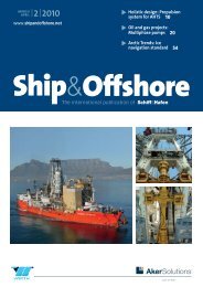
OFFSHORE & MARINE TECHNOLOGY | PROPULSION & MANOEUVRING TECHNOLOGY<br />
Optimising <strong>propulsion</strong><br />
systems for AHTS vessels<br />
HOLISTIC DESIGN <strong>The</strong> bollard pull <strong>of</strong> an AHTS depends not only on the power transmitted to<br />
the propellers but also on the propeller diameter, nozzle <strong>design</strong> and their interaction with each<br />
other and the hull. A 13% increase in bollard pull has been shown, which has been verified by<br />
the full scale results.<br />
Jens Ring Nielsen, Henrik Marinussen<br />
<strong>The</strong> <strong>design</strong> <strong>of</strong> a <strong>propulsion</strong><br />
system for an AHTS is a<br />
challenging task involving<br />
not only the physically products<br />
like engine, gearbox, propellers<br />
and control system but also the<br />
interfaces between these components<br />
as well as their influence<br />
on the vessel’s performance. One<br />
significant example in this respect<br />
is the interaction <strong>of</strong> the propeller<br />
and nozzle with the hull.<br />
Most AHTSs are highly powered<br />
and <strong>design</strong>ed as twin screw vessels<br />
with ducted CP (controllable<br />
pitch) propellers in order to<br />
achieve the required BP (bollard<br />
pull) and a high manoeuvrability.<br />
<strong>The</strong> other operating conditions<br />
seldom play a role in specifying<br />
the main engine power.<br />
However, the BP is not solely determined<br />
by the installed power<br />
but also by an optimised <strong>propulsion</strong><br />
system and hull lines. An<br />
optimum solution is characterised<br />
by a <strong>design</strong> where all three<br />
items have been addressed.<br />
Pre-order stage<br />
Hydrodynamic aspects One <strong>of</strong><br />
the first questions raised, when<br />
starting the <strong>design</strong> <strong>of</strong> an AHTS,<br />
is how much power is needed<br />
to reach a certain specified bollard<br />
pull. For years it has been a<br />
common practise to use simple<br />
rules that would link the bollard<br />
pull to the installed power.<br />
One rule simply states that<br />
each HP will yield 13.6 kg [1].<br />
MAN Diesel developed a more<br />
refined method where the bollard<br />
pull is determined from<br />
the power density i.e. based on<br />
both power and propeller diameter<br />
[2]. That power cannot<br />
be used as a sole parameter to<br />
determine the achievable bollard<br />
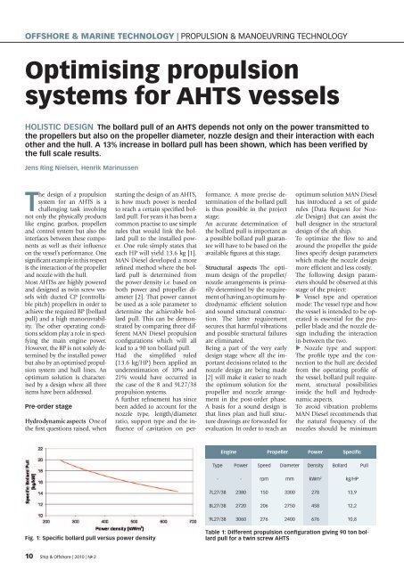
pull. This can be demonstrated<br />
by comparing three different<br />
MAN Diesel <strong>propulsion</strong><br />
configurations which will all<br />
lead to a 90 ton bollard pull.<br />
Had the simplified ruled<br />
(13.6 kg/HP) been applied an<br />
underestimation <strong>of</strong> 10% and<br />
21% would have occurred in<br />
the case <strong>of</strong> the 8 and 9L27/38<br />
<strong>propulsion</strong> systems.<br />
A further refinement has since<br />
been added to account for the<br />
nozzle type, length/diameter<br />
ratio, support type and the influence<br />
<strong>of</strong> cavitation on performance.<br />
A more precise determination<br />
<strong>of</strong> the bollard pull<br />
is thus possible in the project<br />
stage.<br />
An accurate determination <strong>of</strong><br />
the bollard pull is important as<br />
a possible bollard pull guarantee<br />
will have to be based on the<br />
available figures at this stage.<br />
Structural aspects <strong>The</strong> optimum<br />
<strong>design</strong> <strong>of</strong> the propeller/<br />
nozzle arrangements is primarily<br />
determined by the requirement<br />
<strong>of</strong> having an optimum hydrodynamic<br />
efficient solution<br />
and sound structural construction.<br />
<strong>The</strong> latter requirement<br />
secures that harmful vibrations<br />
and possible structural failures<br />
are eliminated.<br />
Being a part <strong>of</strong> the very early<br />
<strong>design</strong> stage where all the important<br />
decisions related to the<br />
nozzle <strong>design</strong> are being made<br />
[2] will make it easier to reach<br />
the optimum solution for the<br />
propeller and nozzle arrangement<br />
in the post-order phase.<br />
A basis for a sound <strong>design</strong> is<br />
that lines plan and hull structure<br />
drawings are forwarded for<br />
evaluation. In order to reach an<br />
optimum solution MAN Diesel<br />
has introduced a set <strong>of</strong> guide<br />
rules (Data Request for Nozzle<br />
Design) that can assist the<br />
hull <strong>design</strong>er in the structural<br />
<strong>design</strong> <strong>of</strong> the aft ship.<br />
To optimize the flow to and<br />
around the propeller the guide<br />
lines specify <strong>design</strong> parameters<br />
which make the nozzle <strong>design</strong><br />
more efficient and less costly.<br />
<strong>The</strong> following <strong>design</strong> parameters<br />
should be observed at this<br />
stage <strong>of</strong> the project:<br />
Vessel type and operation<br />
mode: <strong>The</strong> vessel type and how<br />
the vessel is intended to be operated<br />
is essential for the propeller<br />
blade and the nozzle <strong>design</strong><br />
including the interaction<br />
in-between the two.<br />
Nozzle type and support:<br />
<strong>The</strong> pr<strong>of</strong>ile type and the connection<br />
to the hull are decided<br />
from the operating pr<strong>of</strong>ile <strong>of</strong><br />
the vessel, bollard pull requirement,<br />
structural possibilities<br />
inside the hull and hydrodynamic<br />
aspects.<br />
To avoid vibration problems<br />
MAN Diesel recommends that<br />
the natural frequency <strong>of</strong> the<br />
nozzles should be minimum<br />
Engine Propeller Power Specific<br />
Type Power Speed Diameter Density Bollard Pull<br />
- - rpm mm kWm 2 kg/HP<br />
7L27/38 2380 150 3300 278 13,9<br />
8L27/38 2720 206 2750 458 12,2<br />
9L27/38 3060 276 2400 676 10,8<br />
Fig. 1: Specific bollard pull versus power density<br />
Table 1: Different <strong>propulsion</strong> configuration giving 90 ton bollard<br />
pull for a twin screw AHTS<br />
10 Ship & Offshore | 2010 | N o 2
Fig. 2: Strut and headbox support<br />
20% above or below the first<br />
order natural frequency <strong>of</strong> the<br />
propeller blades. <strong>The</strong> stiffness<br />
<strong>of</strong> the nozzle pr<strong>of</strong>ile itself, the<br />
connection type to the hull<br />
and the aft ship stiffness forms<br />
the basis for this evaluation.<br />
A sound <strong>design</strong> is characterised<br />
by having a well distribution<br />
<strong>of</strong> forces and by avoiding<br />
stress raisers. <strong>The</strong> <strong>design</strong> <strong>of</strong> the<br />
top strut and headbox is a special<br />
challenge in this respect.<br />
However, the structural aspects<br />
must always be balanced by<br />
the hydrodynamic requirements.<br />
Post-order stage<br />
<strong>The</strong> detailed <strong>design</strong> usually<br />
takes place after signing the<br />
contract when more information<br />
is available on the hull<br />
lines, engine, gearbox and shaft<br />
arrangement.<br />
<strong>The</strong> items that are usually addressed<br />
are:<br />
Aft ship hull form <strong>design</strong>.<br />
<strong>The</strong> achievable bollard pull depends<br />
on the aft ship lines and<br />
the propeller and shaft arrangement.<br />
In general the water flow<br />
around the hull will follow the<br />
buttock lines. This means the<br />
slope <strong>of</strong> the buttock lines is<br />
<strong>of</strong> great importance as it will<br />
influence the thrust deduction<br />
factor.<br />
t = 1 -<br />
T BP<br />
T P,B<br />
+ T N,B<br />
From the formula it can be seen<br />
that the propeller and nozzle<br />
thrust in behind condition T P,B<br />
and T N,B<br />
is reduced by the thrust<br />
deduction factor t – leading to<br />
a corresponding reduction in<br />
the bollard pull. This reduction<br />
is mainly caused by the suction<br />
<strong>of</strong> the propeller and nozzle on<br />
the adjacent hull surfaces. For<br />
that reason the distance from<br />
where the shaft protrudes from<br />
the hull to the centre <strong>of</strong> the<br />
propeller should be as long as<br />
possible. It is MAN Diesel’s recommendation<br />
to <strong>design</strong> slowly<br />
raising buttock hull lines <strong>of</strong><br />
approximately 17-19 degrees.<br />
<strong>The</strong> overall aim is to keep the<br />
thrust deduction factor to a<br />
minimum. Furthermore, it<br />
must be secured that sufficient<br />
water will be present above the<br />
propeller/nozzle in order to<br />
prevent air suction.<br />
Propeller blade <strong>design</strong>. <strong>The</strong><br />
detailed <strong>design</strong> <strong>of</strong> the propeller<br />
blades will be based on the<br />
different operating conditions<br />
and the results from the model<br />
tests (resistance, self <strong>propulsion</strong><br />
with stock propeller, wake<br />
measurements). <strong>The</strong> blades will<br />
be optimised for the bollard<br />
pull condition and checked<br />
for different other operating<br />
modes (free sailing, towing etc)<br />
to ensure that an overall optimum<br />
<strong>design</strong> has been reached.<br />
<strong>The</strong> final <strong>design</strong> will be based<br />
on a balance between the two<br />
major <strong>design</strong> objectives – efficiency<br />
and cavitation/vibration.<br />
<strong>The</strong> detailed <strong>design</strong> <strong>of</strong> the<br />
Fig 3: Definition <strong>of</strong> tilt and azimuth angles<br />
propeller and nozzle is made<br />
in close cooperation between<br />
the hydrodynamic and structural<br />
engineer. For AHTS the<br />
shape <strong>of</strong> the blades will exhibit<br />
wide chords at the tip (Kaplan<br />
shape) to maximise the bollard<br />
pull.<br />
Nozzle <strong>design</strong>. <strong>The</strong> type <strong>of</strong><br />
nozzle has already been selected<br />
in the pre-order phase<br />
and the detailed <strong>design</strong> <strong>of</strong> the<br />
nozzle will focus on the support<br />
and hull attachments to<br />
minimise the thrust deduction<br />
caused by the interaction effects<br />
with the hull. Compared<br />
to the conventional nozzle<br />
types the AHT nozzle will deliver<br />
more thrust thus making<br />
the <strong>design</strong> details <strong>of</strong> the support<br />
more important in order<br />
to minimise the thrust deduction<br />
factor.<br />
Consequently, only a plant<br />
specific <strong>design</strong>ed propeller and<br />
nozzle including well faired<br />
and structurally sound supports<br />
will result in an optimum<br />
solution. This means that the<br />
propeller and nozzle supplier<br />
needs to be a part <strong>of</strong> the very<br />
early <strong>design</strong> stage as already<br />
underlined in reference [2]. <br />
Ship & Offshore | 2010 | N o 2 11
OFFSHORE & MARINE TECHNOLOGY | PROPULSION & MANOEUVRING TECHNOLOGY<br />
Fig. 4: CFD pressure calculation <strong>of</strong> nozzle and propeller<br />
Fig. 5: Comparison <strong>of</strong> astern bollard pull, AHT versus 19A both<br />
with L/D=0.5<br />
To verify the potential <strong>of</strong> the different <strong>design</strong><br />
alternatives MAN Diesel recommends to<br />
make model test <strong>of</strong> the final <strong>design</strong>ed propeller<br />
and nozzle, including test <strong>of</strong> tilt and<br />
azimuth angles <strong>of</strong> nozzle as well as propeller<br />
direction <strong>of</strong> rotation.<br />
<strong>The</strong> possible improvement that can be<br />
achieved by following this systematic approach<br />
will be exemplified by the following<br />
case study. However, it is important to note<br />
that the more aligning requirements that are<br />
proposed for the nozzle, the more cumbersome<br />
the installation will be. In each case, the<br />
gain obtained in bollard pull by introducing<br />
an additional nozzle alignment requirement<br />
should be carefully judged against the risk <strong>of</strong><br />
possible misalignment during installation.<br />
In any case MAN Diesel recommends choosing<br />
the same supplier for the propeller and<br />
the nozzle to optimise the overall performance.<br />
Latest nozzle development<br />
Since the introduction <strong>of</strong> the AHT nozzle<br />
its range has been extended to include:<br />
longer and shorter nozzles than the<br />
original L/D=0.5 making it possible to select<br />
the most optimum size depending on<br />
cavitation number and propeller load<br />
a simplified and more production version<br />
with a strait inner area at the propeller<br />
zone.<br />
<strong>The</strong> nozzle family was developed using<br />
CFD calculations on a large number <strong>of</strong> systematically<br />
varied nozzle shapes and with<br />
the bollard pull conditions as the prime<br />
optimisation objective.<br />
A major research program was recently undertaken<br />
by MAN Diesel to investigate the<br />
performance <strong>of</strong> ducted propellers including<br />
the influence <strong>of</strong> cavitation. Different<br />
types <strong>of</strong> AHT nozzles and the well known<br />
19A nozzles were tested at SVA Potsdam as<br />
well as in the Free Surface cavitation tunnel<br />
at the University <strong>of</strong> Berlin.<br />
Most propellers – being open or ducted – are<br />
<strong>design</strong>ed with a certain amount <strong>of</strong> cavitation<br />
and if kept within limits the cavitation<br />
will only affect the performance marginally.<br />
However, this is not true for highly loaded<br />
ducted propellers where the present <strong>of</strong> cavitation<br />
reduces especially the nozzle thrust.<br />
One aspect that became clear was the importance<br />
<strong>of</strong> minimising the tip clearance<br />
because the tip vortex would disturb the<br />
flow at the exit <strong>of</strong> the nozzle. However, for<br />
practical reason a certain clearance is necessary<br />
to facilitate the dismantling <strong>of</strong> the<br />
blades inside the nozzle.<br />
An extensive test series was carried out in<br />
both non- and cavitating conditions for the<br />
AHT series <strong>of</strong> nozzle as well as the 19A version.<br />
<strong>The</strong> results can be summarised as:<br />
<strong>The</strong> AHT nozzles showed superior performance<br />
compared to the 19A.<br />
<strong>The</strong> shorter nozzles are more affected<br />
by cavitation than the longer versions.<br />
Air suction from the water surface into<br />
the propeller/nozzle reduces the bollard<br />
pull significantly. <strong>The</strong> risk increases with<br />
diminishing water height above the propeller<br />
and increasing L/D ratios<br />
<strong>The</strong> backing performance <strong>of</strong> the different<br />
nozzles also formed a part <strong>of</strong> the investigation<br />
and clearly showed the superiority <strong>of</strong><br />
Fig. 6: An AHT Ø4030 nozzle ready for dispatch. Leading edge<br />
<strong>of</strong> the nozzle is on the floor.<br />
Fig. 7: Finite Element vibration analysis <strong>of</strong> nozzle including<br />
supports<br />
12 Ship & Offshore | 2010 | N o 2
Torquemotors<br />
Direct Drives from<br />
100 to 150000 Nm<br />
Fig 8: Stepwise improvement in bollard pull for a 120 ton AHTS<br />
the new AHT nozzle family. A 20-25% improvement<br />
<strong>of</strong> the astern thrust was measured<br />
compared to the 19A type.<br />
Case study<br />
<strong>The</strong> case study concerns a series <strong>of</strong> AHTS<br />
vessels <strong>design</strong>ed to deliver a bollard pull<br />
<strong>of</strong> 120 tons with a MAN Diesel <strong>propulsion</strong><br />
system.<br />
<strong>The</strong> initial hull lines developed by the naval<br />
architect displayed steep buttock lines<br />
<strong>of</strong> approx. 25° exceeding the recommended<br />
17- 19°. <strong>The</strong> buttock lines were later reduced<br />
to 23° by lowering the gearbox followed by<br />
a re<strong>design</strong> <strong>of</strong> the aft ship. In addition the<br />
distance between the propeller and where<br />
the shaft protrudes from the hull is short.<br />
Because <strong>of</strong> these unfavourable conditions<br />
the thrust deduction factor ended up being<br />
9.6%.<br />
A comprehensive model testing program<br />
was set up to investigate the possible improvements<br />
from not only using the new<br />
AHT nozzle type but also including other<br />
relevant installation aspects. Apart from<br />
the normal testing with stock propeller the<br />
following were added:<br />
Nozzle supports comprising both a<br />
headbox and a strut solution<br />
Propeller direction <strong>of</strong> rotation<br />
Nozzle types – AHT and 19A<br />
Tilting and azimuthing <strong>of</strong> nozzles.<br />
<strong>The</strong> model testing program was planned in<br />
the sequence as described above and lead<br />
to an increasing improvement <strong>of</strong> the bollard<br />
pull as the testing proceeded.<br />
Especially the testing with the AHTS nozzle<br />
showed a pronounced improvement in<br />
bollard pull.<br />
Varying the azimuth angle <strong>of</strong> the nozzle<br />
only resulted in a marginally improvement<br />
and was for this reason not applied.<br />
Compared to a standard solution a 13%<br />
improvement in bollard was achieved by<br />
following this systematic approach.<br />
<strong>The</strong> full scale testing was conducted as<br />
the vessels were commissioned and at<br />
the time being 5 vessels had their bollard<br />
pull measured. <strong>The</strong> full scale figures are<br />
as measured and not corrected for the<br />
unfavourable conditions at the test site<br />
(limited water depth and current across<br />
tow line) as required in [5]. This type <strong>of</strong><br />
vessel falls into the standard 120 ton category<br />
<strong>of</strong> AHTS’s which up to now have<br />
been characterised by having two 8 cylinder<br />
32cm bore main engines with a<br />
rated power <strong>of</strong> 4,000 kW. Compared to<br />
this industry standard the MAN Diesel<br />
optimised <strong>propulsion</strong> solution can suffice<br />
with only 2x3,285 kW to reach the<br />
required bollard pull.<br />
References:<br />
[1] Oosterveld, M.W.C. (1970). Wake<br />
Adapted Ducted Propellers, Publication<br />
No. 345 NSMB, Wageningen, Netherlands<br />
[2] Nielsen, J. R., Jeppesen R. M. and Lundgren,<br />
E., (2005) Propulsion <strong>of</strong> Offshore<br />
Support Vessels, OSV Conference, Singapore<br />
[3] Jeppesen, R. M., Marinussen, H., (2006)<br />
Latest trends in Offshore Propulsion,<br />
SNAMES Technical talk, Singapore<br />
[4] Minchev, A., Nielsen, J.R., Lundgren, E.,<br />
(2009) Ducted propeller Design and Verification<br />
for Contempoary Offshore Support<br />
Vessels, First international Symposium on<br />
Marine Propulsors, Torndheim, Norway<br />
[5] Boesen, K. (2005). Bollard Pull trials,<br />
Internal MAN Diesel document<br />
<strong>The</strong> authors:<br />
Jens Ring Nielsen (Senior Manager),<br />
Henrik Marinussen,<br />
(Research Engineer, Propulsion R&D),<br />
MAN Diesel SE, Frederikshavn,<br />
Denmark<br />
· powerful and cost<br />
effective<br />
· individually <strong>design</strong>ed,<br />
customizable to your<br />
operation conditions<br />
in the best way<br />
· large sized open inner<br />
diameter for constructive<br />
advantages<br />
· for high peak torque<br />
and noise reduction<br />
Ask for the cost effective<br />
individual <strong>design</strong>ed<br />
drive solutions made by<br />
OSWALD.<br />
See www.oswald.de<br />
for details.<br />
REGELBARE ELEKTROMOTOREN<br />
REGELBARE ELEKTROMOTOREN<br />
Benzstraße 12 . D-63897 Miltenberg<br />
Phone ++49 (0 )93 71 9 71 90<br />
Telefax ++49 (0 )93 71 97 19 50<br />
oswald@oswald.de