POLYMIN - University of Waterloo
POLYMIN - University of Waterloo
POLYMIN - University of Waterloo

Create successful ePaper yourself
Turn your PDF publications into a flip-book with our unique Google optimized e-Paper software.
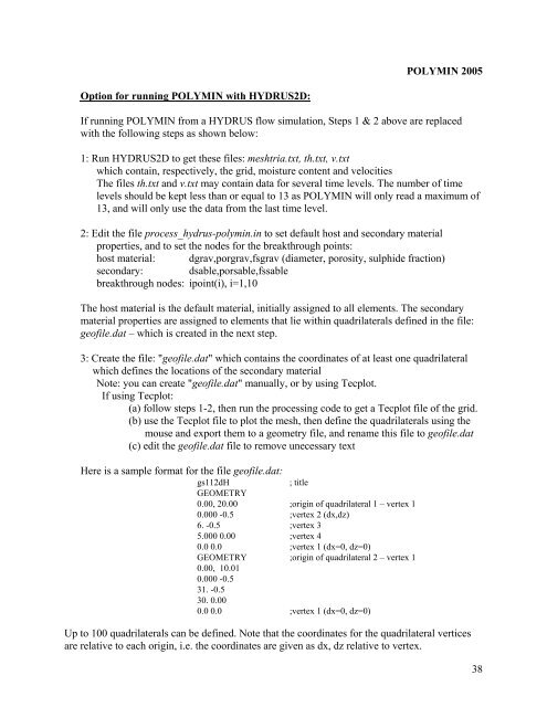
<strong>POLYMIN</strong> 2005<br />
Option for running <strong>POLYMIN</strong> with HYDRUS2D:<br />
If running <strong>POLYMIN</strong> from a HYDRUS flow simulation, Steps 1 & 2 above are replaced<br />
with the following steps as shown below:<br />
1: Run HYDRUS2D to get these files: meshtria.txt, th.txt, v.txt<br />
which contain, respectively, the grid, moisture content and velocities<br />
The files th.txt and v.txt may contain data for several time levels. The number <strong>of</strong> time<br />
levels should be kept less than or equal to 13 as <strong>POLYMIN</strong> will only read a maximum <strong>of</strong><br />
13, and will only use the data from the last time level.<br />
2: Edit the file process_hydrus-polymin.in to set default host and secondary material<br />
properties, and to set the nodes for the breakthrough points:<br />
host material: dgrav,porgrav,fsgrav (diameter, porosity, sulphide fraction)<br />
secondary: dsable,porsable,fssable<br />
breakthrough nodes: ipoint(i), i=1,10<br />
The host material is the default material, initially assigned to all elements. The secondary<br />
material properties are assigned to elements that lie within quadrilaterals defined in the file:<br />
ge<strong>of</strong>ile.dat – which is created in the next step.<br />
3: Create the file: "ge<strong>of</strong>ile.dat" which contains the coordinates <strong>of</strong> at least one quadrilateral<br />
which defines the locations <strong>of</strong> the secondary material<br />
Note: you can create "ge<strong>of</strong>ile.dat" manually, or by using Tecplot.<br />
If using Tecplot:<br />
(a) follow steps 1-2, then run the processing code to get a Tecplot file <strong>of</strong> the grid.<br />
(b) use the Tecplot file to plot the mesh, then define the quadrilaterals using the<br />
mouse and export them to a geometry file, and rename this file to ge<strong>of</strong>ile.dat<br />
(c) edit the ge<strong>of</strong>ile.dat file to remove unecessary text<br />
Here is a sample format for the file ge<strong>of</strong>ile.dat:<br />
gs112dH<br />
; title<br />
GEOMETRY<br />
0.00, 20.00 ;origin <strong>of</strong> quadrilateral 1 – vertex 1<br />
0.000 -0.5 ;vertex 2 (dx,dz)<br />
6. -0.5 ;vertex 3<br />
5.000 0.00 ;vertex 4<br />
0.0 0.0 ;vertex 1 (dx=0, dz=0)<br />
GEOMETRY ;origin <strong>of</strong> quadrilateral 2 – vertex 1<br />
0.00, 10.01<br />
0.000 -0.5<br />
31. -0.5<br />
30. 0.00<br />
0.0 0.0 ;vertex 1 (dx=0, dz=0)<br />
Up to 100 quadrilaterals can be defined. Note that the coordinates for the quadrilateral vertices<br />
are relative to each origin, i.e. the coordinates are given as dx, dz relative to vertex.<br />
38