Racecar Engineering - November 2005
Racecar Engineering - November 2005
Racecar Engineering - November 2005

Create successful ePaper yourself
Turn your PDF publications into a flip-book with our unique Google optimized e-Paper software.
Aero tips<br />
But, as Carroll Smith also pointed out, it’s not<br />
just the drag of the fastener themselves that<br />
matters, but the wakes extending rearwards from<br />
them. Just think about the shape of a wake you<br />
can see easily, such as that from a boat moving<br />
through water. Depending on the exact<br />
circumstances, the wake spreads out downstream<br />
and potentially affects the flow to other parts of<br />
the racecar, as well as causing drag and local flow<br />
separation. So to really offend an aerodynamicist,<br />
just attach your Gurney to the underside of your<br />
wing and use hex headed bolts to hold the thing in<br />
place! If you do use nuts and bolts to hold a<br />
Gurney on, at least use the dome-headed type<br />
(wing trailing edges are generally too thin for<br />
countersunk or flush fasteners) with the heads on<br />
the underside, and the more obtrusive nut and<br />
bolt shank on the upper surface where they sit<br />
ahead of the vertical portion of the Gurney and<br />
have minimal influence.<br />
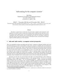
Moving on to protruding edges, borrowing<br />
once more from Carroll Smith and Tune to Win.<br />
Figure 5 shows the drag coefficients of various<br />
sheet metal joints, and again the conclusions are<br />
pretty obvious. Yet the occurrence of forward<br />
facing edge overlaps is all too frequent, especially<br />
so on the flat aluminium sheets used to panel in<br />
the underside of racecars. Panelling in the<br />
underside is aerodynamically a good thing to do<br />
(providing cooling has also been carefully<br />
considered), but leaving forward facing<br />
protruding edges clearly negates some of the<br />
effort. The designs in figure 5 point at the most<br />
aerodynamically efficient ways of joining such<br />
panels, and the small amount of extra effort will<br />
surely be worthwhile.<br />
There’s a tale told of a well-known racecar<br />
C D<br />
= 0.70<br />
C D<br />
= 0.70<br />
C D<br />
= 0.5<br />
Velocity<br />
Boundary layer thickness = .307 inches<br />
.275”<br />
–5°<br />
–1° –7°<br />
–2°<br />
–10° +5°<br />
.190”<br />
.22”<br />
.22”<br />
manufacturer’s managing director who had the<br />
habit of running his thumbnail across the joins in<br />
bodywork after initial assembly to ensure they<br />
were as tight fitting and smooth as possible – not<br />
very scientific perhaps, but a valid inspection<br />
technique nevertheless. And you can see his<br />
reasoning – with all the effort put into CFD and<br />
wind tunnel development programmes, it was<br />
vital that there were no major tolerance problems<br />
on the finished product. But a good fit between<br />
body panels is vital whether or not you’ve<br />
Relative surface drag<br />
1.39<br />
1.20<br />
1.00<br />
1.62<br />
1.17<br />
1.28<br />
6.66<br />
h<br />
V<br />
h = 1 / 2<br />
b<br />
V<br />
h = b<br />
Figure 6: relative drag<br />
caused by different<br />
shaped gaps in panels<br />
Figure 7: thin tape over<br />
gaps in bodywork can<br />
help reduce drag<br />
Below – figure 8: relative<br />
drag caused by scratches<br />
and ridges on bodywork<br />
Relative surface drag<br />
b<br />
b<br />
h<br />
1<br />
80<br />
C D<br />
= 0.11<br />
C D<br />
= –0.04<br />
C D<br />
= 0.13<br />
C D<br />
= 0.24<br />
C D<br />
= 0.01<br />
C D<br />
= 0.24<br />
C D<br />
= 0.16<br />
C D<br />
= 0.07<br />
Figure 5: drag coefficients of all the major joint<br />
types between sheet metal bodywork sections<br />
“<br />
CERTAIN GAP SHAPES<br />
CREATE APPALLING<br />
DRAG<br />
”<br />
developed your car on a computer or in a wind<br />
tunnel. Figure 6 once again appears in Milliken<br />
and Milliken, and originates in that 1963 paper.<br />
Although this time the drag numbers are relative<br />
to the third example from the top, we can see<br />
from the second example from the bottom of<br />
figure 5 that if a simple, shallow gap creates<br />
significant drag, then it is probably fair to assume<br />
that wider and deeper gaps will be worse. And<br />
figure 6 tells us that certain gap shapes create<br />
appalling drag.<br />
An easy and frequently used way of improving<br />
V<br />
h = b<br />
130<br />
body fit at the track is to tape over the joins,<br />
preferably with very thin tape. This at least will be<br />
better than leaving large gaps. Similarly, where<br />
body cut outs have been made, to clear<br />
suspension legs for example, these can be taped<br />
over to bridge the gap (see photo figure 7). Body<br />
fasteners may beneficially be taped over, too.<br />
Scratches and ridges have also been examined<br />
to see their effect on skin friction drag, and figure<br />
8 illustrates, this also coming from that 1963 paper<br />
via Milliken and Milliken. Although actual<br />
dimensions are missing in this figure, we can at<br />
b<br />
h<br />
➔<br />
56 <strong>November</strong> <strong>2005</strong> <strong>Racecar</strong> <strong>Engineering</strong><br />
www.racecar-engineering.com