Racecar Engineering - November 2005
Racecar Engineering - November 2005
Racecar Engineering - November 2005

You also want an ePaper? Increase the reach of your titles
YUMPU automatically turns print PDFs into web optimized ePapers that Google loves.
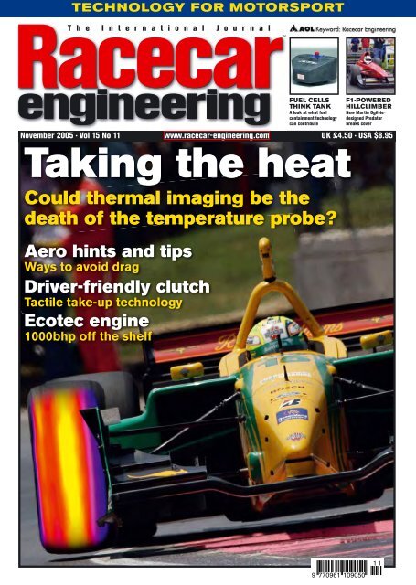
TECHNOLOGY FOR MOTORSPORT<br />
T h e I n t e r n a t i o n a l J o u r n a l<br />
<br />
Taking the heat<br />
Could thermal imaging be the<br />
death of the temperature probe?<br />
Aero hints and tips<br />
Ways to avoid drag<br />
Driver-friendly clutch<br />
Tactile take-up technology<br />
Ecotec engine<br />
1000bhp off the shelf<br />
FUEL CELLS<br />
THINK TANK<br />
A look at what fuel<br />
containment technology<br />
can contribute<br />
F1-POWERED<br />
HILLCLIMBER<br />
New Martin Ogilviedesigned<br />
Predator<br />
breaks cover<br />
<strong>November</strong> <strong>2005</strong> · Vol 15 No 11 www.racecar-engineering.com UK £4.50 · USA $8.95<br />
9 770961 109050<br />
1 1
Contents<br />
NOVEMBER <strong>2005</strong><br />
Features<br />
Cover story<br />
32 Hot rubber<br />
Thermal cameras could change the science of<br />
taking tyre temperatures. We test the theory<br />
38 The science of ambition<br />
Graeme Wight junior’s hillclimb car shows reality<br />
need never get in the way of a good idea<br />
48 Ecotec friendly<br />
An all aluminium, four-cylinder, DOHC engine<br />
from GM aimed directly at motorsport<br />
54 Aero bite size<br />
The minutiae of aerodynamics. How the most<br />
insignificant component can have an effect<br />
62 Cushioning the blow<br />
AP Racing’s new clutch system aims to take the<br />
strain out of getting off the line<br />
32<br />
Sam Collins<br />
Raceworld<br />
05 Write line – Does a competitor’s death prove<br />
the current rally format is unsustainable?<br />
06 Debrief – Red Bull takes over at Minardi, FIA<br />
gets into CFD and LMP900 gets a reprieve<br />
38<br />
Simon McBeath<br />
18 Race people – Geoff Goddard of Geoff<br />
Goddard Engines Ltd is On The Gas<br />
23 V-Angles – Paul Van Valkenburgh remembers<br />
how tyre testing used to be<br />
27 Column – Mike Breslin on the rise and fall of<br />
motor racing circuits<br />
31 Forum – More feedback on Formula Student<br />
and a dressing down for an Autocad fan<br />
Raceshop<br />
69 Buyers’ insight – Fuel cells, their<br />
development, manufacture and application<br />
75 Tech spotlight – 3D-connexion makes light<br />
work of CAD with its new, intelligent controller<br />
77 Racegear – All the latest products<br />
48<br />
GM<br />
83 Database – Full motorsport supplier listings<br />
93 Aerobytes – Simon McBeath examines how to<br />
make the most of waste exhaust gases<br />
97 The Consultant – Is there ever such a thing<br />
as too much left percentage in oval racing?<br />
Subscriptions<br />
FOR SUBSCRIPTION DETAILS TURN TO<br />
PAGE 67<br />
Or visit www.racecar-engineering.com<br />
54<br />
Advantagee CFD<br />
www.racecar-engineering.com<br />
<strong>November</strong> <strong>2005</strong> <strong>Racecar</strong> <strong>Engineering</strong><br />
3
Write Line<br />
Everyone in the <strong>Racecar</strong> <strong>Engineering</strong> office was stunned to hear of the<br />
death of Michael Park, Markko Martin’s co-driver, on the Rally GB.<br />
Thankfully we have not lost a World Rally competitor since the death<br />
of Henri Toivonen and Sergio Cresto in 1986. However, events over<br />
recent seasons have exhibited a number of alarmingly heavy accidents.<br />
Fortunately the crews have all survived, most without serious injury, but each<br />
incident has left an uneasy feeling that things could have been worse.<br />
Tragically that has now happened.<br />
Why these accidents are happening is something I have pondered on before<br />
in this column [V13N2], but the subject is probably worth revisiting.<br />
The last time there was a fatality, world rallying was in the grip of Group B,<br />
the rules that allowed enormous freedom for constructors. Low production<br />
requirements to achieve homologation opened the door for very powerful,<br />
fast cars. However, they also proved dangerous and were banned<br />
following the Toivonen crash. But the cars competing today are at least as<br />
quick over a stage mile,<br />
even if they are more<br />
“<br />
RALLY STAGES ARE NOT<br />
LIKE RACING CIRCUITS<br />
”<br />
predictable and<br />
forgiving.<br />
But speed is not the<br />
only issue. Rally stages<br />
are not like racing<br />
circuits. They lack runoff<br />
area, crash barriers or gravel traps. Instead they have ditches, banks, long<br />
drops and, worst of all, trees. Even at a relatively modest speed, the<br />
concentration of force a tree generates on a rally car ’shell is considerable. It<br />
is impossible to make the car strong enough to resist this force in all cases<br />
because if the car doesn’t deform then the sudden deceleration will prove<br />
fatal. Nor is it practical to remove all the trees or wrap them in crash barriers.<br />
Apart from the logistics, the trees are an intrinsic part of what makes a forest<br />
a forest. Take them away and you change the nature of the event.<br />
The alternatives are to take the cars out of the forests and put them in a<br />
more controlled environment. We already do that and call it Rallycross. Or,<br />
we change the emphasis of the sport of rallying. At the risk of sounding like an<br />
old git, years ago world rallies were very different events. Lasting for four or<br />
five days, going through the night on occasions, they had punishing schedules<br />
and covered hundreds of miles between stages. They had a strong endurance<br />
element and gaining results called for an ability to keep going and avoid<br />
trouble. They forced a degree of caution and margin for safety in both the<br />
teams and the crews. Today’s events are more like sprints, always run in<br />
daylight and with very limited road mileage.<br />
Consequently, all resources can be channelled into<br />
producing the best possible stage times. Crews drive<br />
on the absolute limit with no margin and the crashes,<br />
when they happen, are huge.<br />
Rallies are not races, they can never deliver a neatly<br />
packaged three hours of entertainment on a Sunday<br />
afternoon. Let them return to being endurance events<br />
and promote them in the same way as Le Mans or the<br />
rallies of the 1960s and ’70s. That way the emphasis<br />
will shift away from pure speed, the events will survive<br />
the regulators and, most importantly, more lives will<br />
not be lost.<br />
Editor<br />
Charles Armstrong-Wilson<br />
Pit Crew<br />
Vol 15 No.11<br />
Editor<br />
Charles Armstrong-Wilson<br />
Deputy Editor<br />
Sam Collins<br />
Art Editor<br />
Barbara Stanley Borras<br />
Chief Sub Editor<br />
Mike Pye<br />
Editorial Assistant<br />
Katie Power<br />
Contributing Editors<br />
Paul Van Valkenburgh, Allan Staniforth<br />
Technical Consultant<br />
Peter Wright<br />
Group Art Editor<br />
Patrick Morrissey<br />
Contributors<br />
George Bolt Jr, Mike Breslin, Dan Carney, Charles<br />
Clarke, Simon McBeath, Mark Ortiz,<br />
Martin Sharp, Ian Wagstaff<br />
Photography<br />
LAT, Tony Tobias<br />
Business Development Manager<br />
Tony Tobias +44 (0) 20 8726 8328<br />
Mobile 07768 244880 Fax +44 (0) 20 8726 8399<br />
tony_tobias@ipcmedia.com<br />
Advertisement Sales Executive<br />
Andy King +44 (0) 20 8726 8329<br />
andy_king@ipcmedia.com<br />
Group Advertisement Manager<br />
Kevin Attridge<br />
Publisher<br />
Gavin de Carle<br />
General Manager<br />
Niall Clarkson<br />
Managing Director<br />
Paul Williams<br />
Editorial & Advertising<br />
<strong>Racecar</strong> <strong>Engineering</strong>, Focus Network,<br />
Leon House, 233 High Street,<br />
Croydon, Surrey CR9 1HZ, UK<br />
Tel +44 (0)20 8726 8364<br />
Fax +44 (0)20 8726 8399<br />
E-mail racecar@ipcmedia.com<br />
Back Numbers John Denton Services,<br />
Unit 1 A1 Parkway. South Gate Way,<br />
Orton South Gate, Peterborough PE2 6YN, UK<br />
Tel +44 (0)1733 370800<br />
Fax +44 (0)1733 239356<br />
Worldwide News Trade Distribution<br />
Marketforce (UK) 5th Floor, Low Rise, Kings Reach<br />
Tower, Stamford Street, London SE1 9LS, UK<br />
Tel +44 (0)20 7633 3300<br />
Worldwide Subscriptions <strong>Racecar</strong> <strong>Engineering</strong><br />
Subscriptions, PO Box 272, Hayward’s Heath,<br />
West Sussex, RH16 3FS, UK<br />
Typesetting & Repro Planart Ltd<br />
Print Text Benham Goodhead Print<br />
Cover BR Hubbard Printers<br />
Printed in England ISSN No 0961-1096<br />
USPS No 007-969<br />
<strong>Racecar</strong> <strong>Engineering</strong><br />
is a Focus Network publication, published by<br />
IPC Country & Leisure Media Ltd<br />
<strong>Racecar</strong> <strong>Engineering</strong>, incorporating<br />
Cars & Car Conversions and Rallysport,<br />
is published 12 times per annum and is available<br />
on subscription. Although due care has been<br />
taken to ensure that the content of this publication<br />
is accurate and up-to-date, the publisher can<br />
accept no liability for errors and omissions. Unless<br />
otherwise stated, this publication has not tested<br />
products or services that are described herein,<br />
and their inclusion does not imply any form of<br />
endorsement. By accepting advertisements in<br />
this publication, the publisher does not warrant<br />
their accuracy, nor accept responsibility for their<br />
contents. The publisher welcomes unsolicited<br />
manuscripts and illustrations but can accept no<br />
liability for their safe return.<br />
© <strong>2005</strong> IPC Media. All rights reserved.<br />
Reproduction (in whole or in part) of any text,<br />
photograph or illustration contained in this<br />
publication without the written permission of the<br />
publisher is strictly prohibited. <strong>Racecar</strong> <strong>Engineering</strong><br />
(USPS 007-969) is published 12 times per year by<br />
IPC Media Ltd in England. Periodicals postage paid<br />
at Green Brook NJ 08812. US subscriptions cost<br />
$79.00 from EWA, 205 US Highway 22, Green<br />
Brook, NJ 08812, tel: 800 272 2670. Postmaster:<br />
send address changes to <strong>Racecar</strong> <strong>Engineering</strong>,<br />
205 US Hwy 22, Green Brook NJ 08812 USA<br />
www.racecar-engineering.com<br />
www.racecar-engineering.com<br />
<strong>November</strong> <strong>2005</strong> <strong>Racecar</strong> <strong>Engineering</strong><br />
5
Debrief<br />
IMechE<br />
at ASI<br />
January’s Autosport International<br />
show will host the inaugural<br />
International Motorsport<br />
<strong>Engineering</strong> Conference, organised<br />
by the Institution of Mechanical<br />
Engineers on 11 and 12 January<br />
next year. The new event will cover<br />
the full range of motorsport<br />
engineering and will consist of 24<br />
lectures split into one-hour<br />
sessions. Subjects confi rmed so far<br />
are design, analysis, development,<br />
simulation and testing of engines,<br />
transmission, chassis,<br />
aerodynamics and control systems.<br />
IMechE also hopes to showcase a<br />
Formula Student car.<br />
If you would like to receive more<br />
information please contact:<br />
Stephanie Love, IMechE, 1 Birdcage<br />
Walk, London SW1H 9JJ, UK.<br />
Tel: +44 (0) 20 7973 1312,<br />
Email: s_love@imeche.org.uk<br />
Red Bull Minardi<br />
Red Bull, the Austrian energy drink fi rm<br />
that took over Jaguar in 2004,<br />
announced after the qualifying for the<br />
Belgium Grand Prix that it will obtain<br />
100 per cent of Minardi’s shares,<br />
therefore becoming solely responsible<br />
for the team.<br />
The takeover of the Italian team has<br />
come about from Red Bull’s constant<br />
backing of young driving talent. Yet, with<br />
too many drivers and not enough<br />
cockpits, the winning solution was to<br />
buy a second team, as opposed to<br />
sending drivers to the opposition.<br />
Although the 2006 season will now<br />
see two Red Bull teams on the track, the<br />
team has announced that both will<br />
compete completely independently of<br />
each other. The second team, which at<br />
present is still waiting to be named, will<br />
be seen as the ‘rookie’ team in order to<br />
bring in more drivers from feeder series.<br />
Despite claims, Dietrich Mateschitz<br />
Williams tyred out<br />
Williams has modifi ed some of its<br />
bodywork after a succession of right rear<br />
tyre failures at the Turkish Grand Prix.<br />
The team reduced the size of the cars’<br />
diffusers and wing end plates after the<br />
problem appeared in practice, but failed<br />
to prevent a spate of failures during the<br />
race. The cause of the problems is<br />
rumoured to be linked with the fi tment<br />
of new brake parts.<br />
It has also been revealed that in 2006<br />
Williams will be supplied by Bridgestone<br />
tyres, along with current Michelin<br />
runners Toyota.<br />
SEAT Leon WTCC unveiled<br />
SEAT’s new WTCC challenger was revealed to the world last month.<br />
Pictured here is the car in BTCC colours at the British launch.<br />
First Jaguar, now Minardi. Red Bull does indeed give young drivers wings…<br />
has given his assurances that the<br />
Minardi takeover is not part of an<br />
elaborate plan to gain political power.<br />
However, a defi nite shake up between<br />
the teams siding with Bernie Ecclestone<br />
and the FIA is predicted, as Red Bull will<br />
now receive two votes in any decision<br />
making process within Formula 1.<br />
Speaking at the Spa-Francorchamps<br />
circuit, Minardi owner Paul Stoddart<br />
commented that although he will be very<br />
sad to leave the sport he is convinced<br />
that Red Bull has the suffi cient funds<br />
and commitment to take over the team,<br />
ensuring a stable future for the majority<br />
of Minardi’s current employees.<br />
Second test success<br />
for A1 Grand Prix<br />
Paul Ricard hosted the second A1GP group test, now with an even bigger field<br />
LAT LAT<br />
LAT<br />
Russia, Ireland, Germany, Indonesia<br />
and the Czech Republic joined<br />
motorsport’s inaugural world cup<br />
shortly before its second group test<br />
at Paul Ricard in France.<br />
Germany’s franchise is owned by<br />
driver/manager Willi Weber and will<br />
be run by Super Nova.<br />
The fi rst grand prix of nations at<br />
England’s Brands Hatch circuit was<br />
being heavily advertised in the UK<br />
and, as RE closed for press, a large<br />
crowd was expected at the Motor<br />
Sport Vision-owned venue.<br />
6 <strong>November</strong> <strong>2005</strong> <strong>Racecar</strong> <strong>Engineering</strong><br />
www.racecar-engineering.com
Debrief<br />
F1 to undertake CFD aero study<br />
Following the results of the FIA’s fan<br />
survey, AMD has been appointed as<br />
‘offi cial technical partner’ of the<br />
governing body.<br />
One of the very fi rst joint projects<br />
that this new partnership will<br />
undertake is a CFD study into<br />
vehicle aerodynamics, particularly<br />
focussed on developing<br />
aerodynamic regulations that<br />
promote overtaking.<br />
This comes in the wake of<br />
research done last year by<br />
Advantage CFD and published by<br />
<strong>Racecar</strong>, looking into the effects of<br />
two-car airfl ow.<br />
For more information see V14N10.<br />
GM confirms IRL<br />
withdrawal<br />
Advantage CFD<br />
<strong>Racecar</strong> shows<br />
the way again –<br />
F1 at last<br />
committing to a<br />
full CFD<br />
programme,<br />
initially<br />
concentrating on<br />
airflow behaviour<br />
during overtaking<br />
2006 Lola B06/51 Formula Nippon<br />
Lola has released this artist’s impression of what its<br />
new Formula Nippon chassis may look like.<br />
It will be designed to accept either<br />
Toyota or Mugen engines<br />
LAT<br />
Badge engineering - rule changes could allow Cosworth to supply IRL engines<br />
under its own name in the future, now that GM has confirmed it is pulling out<br />
GM has confi rmed its withdrawal from<br />
the Indy Racing League. Currently<br />
Cosworth’s IRL powerplant is badged<br />
Chevrolet and, if the Cosworth units<br />
were withdrawn from the series, it would<br />
leave teams with only one engine choice<br />
as Toyota has already announced its<br />
withdrawal at the end of 2006. Honda,<br />
who now stands to be the series’ sole<br />
engine supplier, has committed to the<br />
series for the foreseeable future.<br />
However, it looks possible that the<br />
rule may be altered to allow Cosworth to<br />
continue to supply engines to the series.<br />
British steam challenge<br />
shows its metal<br />
The British attempt on the steam car<br />
world record is gathering momentum as<br />
the team unveiled its completed chassis<br />
in September. Since last mentioned in<br />
<strong>Racecar</strong> in 2000 (V10N6) many changes<br />
have been made, including turning the<br />
car’s steam turbine through 90 degrees<br />
from transverse to longitudinal. The<br />
turbine has been specially designed and<br />
built for the job after a suitable off-theshelf<br />
unit couldn’t be found.<br />
Chief engineer Glynne Bowsher and<br />
engineering logistics coordinator Frank<br />
Swanston are also confi dent that the<br />
challenge of designing suitable boilers is<br />
nearly fi nished. Testing of the gas-fi red<br />
units has demonstrated their potential to<br />
produce super-heated steam at<br />
temperatures in excess of 700degC. This<br />
should provide the power to push the<br />
127.66mph world record to 200mph+.<br />
The team is aiming to take outright<br />
world records, Bonneville records and<br />
womens’ world records next year.<br />
www.racecar-engineering.com<br />
<strong>November</strong> <strong>2005</strong> <strong>Racecar</strong> <strong>Engineering</strong><br />
7
Debrief<br />
CvO delay<br />
LMP2<br />
Christian Van Oost’s Le Mans<br />
Technoparc-based CvO team has<br />
delayed its LMP2 plans until ‘after<br />
2006’, due to sales of its ‘LMP3’-<br />
type baby prototype not being as<br />
good as expected. CvO had initially<br />
planned to try and get an entry for<br />
the 2006 Le Mans 24 Hours race.<br />
Talk to us<br />
and win<br />
cash<br />
<strong>Racecar</strong> <strong>Engineering</strong> would like you to<br />
give us feedback on the magazine and<br />
the chance to win £150/$270 in the<br />
process. All you have to do is to visit the<br />
magazine’s website at www.racecarengineering.com<br />
and complete the<br />
simple online questionnaire. It only takes<br />
a few minutes and your feedback will<br />
help us make sure that <strong>Racecar</strong><br />
<strong>Engineering</strong> gives you the information<br />
you really want every month.<br />
Chiron<br />
blow over<br />
Chiron’s LMP3-05 (V15N9) suffered<br />
a ‘blow over’ incident during a<br />
BritSports race at Oulton Park just<br />
days after the risk of such an event<br />
was highlighted by RE.<br />
The no.6 car had just exited the<br />
fast uphill left hand sweep of Clay<br />
Hill when its front lifted off the<br />
ground. The resulting fl ip shocked<br />
Chiron staff member Bill Nickless:<br />
‘It was airborne for about 50 to 60<br />
metres and landed right way up on<br />
the barrier.’ It is the fi rst blow over<br />
for an LMP3-type car and has the<br />
manufacturers worried. ‘It’s a<br />
warning. It can happen again, these<br />
cars are going quicker every race,’<br />
said Nickless. The problem could<br />
spread further to many of the fl atbottom<br />
prototypes in competition<br />
around the world.<br />
ALMS extend<br />
LMP900 regulations<br />
IMSA, the governing body of the ALMS,<br />
has extended the life of LMP900 and<br />
LMP675 cars until the end of 2006. This<br />
move allows the dominant Audi R8s to<br />
continue to compete for another year.<br />
So-called hybrid cars will be allowed to<br />
compete in the US-based series until the<br />
end of 2007. ‘The prototype fi eld is going<br />
through an important transition, and this<br />
opens the fi eld up to a wide variety of<br />
cars,’ explained IMSA’s Tim Mayer.<br />
In the possible event of an LMP900<br />
car performing well enough to fi nish in a<br />
position that would normally warrant an<br />
automatic entry into the 24 Hours of Le<br />
LAT<br />
Mans they would effectively be ignored<br />
in favour of the next highest placed full<br />
LMP1 chassis.<br />
Lotus Circuit Car debut<br />
Lotus’s ‘Circuit Car’ made its debut at<br />
Shelsley Walsh in August. According to<br />
vehicle development manager Nick<br />
Adams, Lotus has initially targeted two<br />
markets for the car - track days and<br />
driver training. The Shelsley run<br />
indicated that the new car will also be<br />
suitable for outright competition<br />
although Lotus has no intention of<br />
running a series itself. Lotus believes it<br />
will be suitable for series such as the<br />
AMOC mid-engined championship and<br />
that there could eventually be others,<br />
both in Europe and in the USA.<br />
The prototype performed ‘faultlessly’,<br />
Ian Wagstaff<br />
Audi’s all-conquering R8 gets a years further lifespan under new regulations<br />
IMSA light headed as the<br />
ALMS heads for Utah<br />
In the wake of RE V15N9’s LMP3<br />
cover story it has been rumoured<br />
that a new sports racing series will<br />
be supporting the ALMS in 2006.<br />
IMSA Light is said to be a tightly<br />
controlled lower budget formula<br />
with restrictions on chassis options<br />
and car spec.<br />
IMSA has revealed that the<br />
ALMS will have a round at the brand<br />
new Miller Motorsports Park in<br />
despite only having been run briefl y at<br />
Hethel the week before. A number of<br />
changes will now be made to the front<br />
geometry and the air intakes.<br />
Signifi cantly, the Elise-based ‘Circuit<br />
Old spec cars such as the R8 will be<br />
required to run 50kg of ballast and a<br />
smaller restrictor.<br />
New ‘small’<br />
prototypes<br />
could soon<br />
have a series<br />
of their own<br />
2006. The Tooele, Utah circuit is the<br />
longest in the USA at 4.5 miles.<br />
Car’ will be the fi rst ‘racecar’ to come off<br />
the Lotus production line. The fi rst<br />
customer cars will be available by the<br />
middle of next year.<br />
Ian Wagstaff<br />
The Circuit Car is<br />
a first for Lotus,<br />
being the only<br />
purpose-built<br />
racecar to be<br />
constructed on<br />
the company’s<br />
production line<br />
8 <strong>November</strong> <strong>2005</strong> <strong>Racecar</strong> <strong>Engineering</strong><br />
www.racecar-engineering.com
Debrief<br />
NEWS IN BRIEF<br />
New FSAE announced<br />
Williams has confi rmed that it will be using<br />
Cosworth V8 engines throughout the 2006<br />
Formula 1 season.<br />
Houston will return to the Champ Car<br />
calendar in 2006, bringing the series to 15<br />
rounds in total.<br />
SEAT’s BTCC Toledo Cupra Rs have been<br />
given a 15kg weight reduction to move the<br />
super 2000 spec base weight to 1085kg. The<br />
move comes as part of the attempts to<br />
equalise the performance of British and World<br />
spec touring cars.<br />
Panoz Esperante GTLM customer cars will<br />
be competing in LMES next year, most likely<br />
with Team LNT. Courage Competition has<br />
been involved with the cars European sales.<br />
Formula SAE has a new event in 2006.<br />
FSAE West is to be held at the California<br />
Speedway in June next year. The event<br />
will sit alongside the traditional Formula<br />
SAE event which will run from 17–21<br />
May 2006. FSAE West is scheduled to<br />
take place between 14-17 June.<br />
‘Formula SAE West is being opened to<br />
meet the growing demand of university<br />
teams to compete in North America. For<br />
the past three years all 140 slots at<br />
Formula SAE were sold out,’ explained<br />
Steve Daum, the SAE’s collegiate<br />
manager. ‘Registration for FSAE <strong>2005</strong><br />
fi lled up in just 73 minutes and we know<br />
of over 30 teams that couldn’t get a slot.<br />
With a second competition there should<br />
be space available for every team that<br />
LAT<br />
wants to compete,’ he continued.<br />
Recruiting of event captains, judges,<br />
technical inspectors (scrutineers) and<br />
other volunteers necessary to the<br />
successful running of the event will start<br />
soon. Anyone based in the Los Angeles<br />
area with knowledge of motorsport<br />
engineering and design who might be<br />
interested in becoming involved are<br />
asked to step forward and volunteer.<br />
California<br />
Speedway is to<br />
host the new<br />
event in 2006<br />
‘We picked California Speedway<br />
because it’s a great site where we can<br />
lay out challenging and exciting courses,<br />
and it is also a site that provides<br />
excellent pits and support facilities.<br />
Locating the second competition in<br />
California will make Formula SAE more<br />
accessible to, and lower the travel costs<br />
of, universities on the West coast and<br />
around the Pacifi c Rim.’<br />
Historic Russian marque Russo-Baltique<br />
looks set to return to the track, with A-Level<br />
<strong>Engineering</strong> boss Vladimir Raikhlin planning<br />
to revive the company.<br />
Circuit de Catalunya is planning to increase<br />
its seating capacity by 8000 for the Spanish<br />
Grand Prix next year.<br />
Antonio Ferrari’s Euro International team<br />
will take part in a number of Champ Car<br />
races next season. The team has already<br />
equipped for the campaign.<br />
GP2 cars will have fully reworked aero next<br />
year, along with slick tyres. Bridgestone is<br />
likely to continue as the single tyre supplier.<br />
MoTeC and<br />
Rouelle go<br />
on tour<br />
The European leg of the ever-popular<br />
<strong>Racecar</strong> Dynamics and Data Acquisition<br />
Seminars, presented by Claude Rouelle,<br />
begins this <strong>November</strong>, with courses in<br />
Italy, France, Germany and the UK. The<br />
fi nal ’06 seminar will be held in Orlando,<br />
USA after the December PRI show.<br />
<strong>November</strong> dates are: 5-7 USA; 11-13<br />
Italy; 15-17 France; 19-21 Germany;<br />
23-25 and 26-28 UK (the second UK<br />
date being a Formula Student special).<br />
Aussie rules spreads its wings<br />
Aussie V8s will rumble their way to<br />
the Middle East next year with a<br />
round at the Bahrain International<br />
Circuit during <strong>November</strong>. The 2006<br />
calendar also sees China make a<br />
return after the fi rst races took<br />
place there this year.<br />
V8 Supercars return to China and<br />
head to the Middle East in 2006<br />
Motor racing Bajan-style<br />
Barbados’s biggest and most<br />
spectacular circuit racing event<br />
– the Internationals Showdown –<br />
attracted an impressive 69<br />
entries this year, mostly domestic<br />
and from Guyana, but the<br />
organisers are pushing for the<br />
event to expand further. See<br />
future issues of <strong>Racecar</strong> for more<br />
details.<br />
LAT<br />
2006 V8 Supercar Championship Series calendar<br />
23-26 March Clipsal 500 Adelaide<br />
30 March-2 April Australian Grand Prix Melbourne*<br />
21-23 April Placemakers V8 International New Zealand<br />
12-14 May V8 300 Perth<br />
9-11 June Shanghai Round China**<br />
30 June-2 July Sky City Triple Crown Darwin<br />
21-23 July Queensland 300 Ipswich<br />
11-13 August Oran Park Sydney<br />
8-10 September Betta Electrical 500 Melbourne<br />
5-8 October Super Cheap Auto 1000 Bathurst<br />
19-22 October V8 Supercar Challenge Gold Coast<br />
10-12 <strong>November</strong> Ferodo Triple Challenge Launceston<br />
22-24 <strong>November</strong> Bahrain International Circuit Bahrain<br />
8-10 December Grand Finale Phillip Island***<br />
*Denotes non-championship event<br />
**Denotes date subject to fi nal FIA and FASC approvals<br />
***Denotes provisional<br />
Sam Collins<br />
www.racecar-engineering.com<br />
<strong>November</strong> <strong>2005</strong> <strong>Racecar</strong> <strong>Engineering</strong><br />
11
Debrief<br />
NASCAR news with George Bolt Jr<br />
Softly,<br />
softly<br />
In one of the most serious NASCAR<br />
rule infractions in recent years<br />
NASCAR suspended Busch Series<br />
crew chief Brian Pattie and tyre<br />
specialist Brandon Stafford for six<br />
races, while the Ganassi team was<br />
deducted 50 car-owner points and<br />
Pattie was fi ned $35,000 when they<br />
were caught applying a tyre<br />
softening compound to the tyres of<br />
a Ganassi Dodge at Bristol.<br />
The Ganassi car was not allowed<br />
to qualify for the race and started at<br />
the rear of the fi eld after the team<br />
was forced to buy new tyres and the<br />
original three sets were confi scated<br />
by NASCAR. Ganassi did not appeal<br />
the fi ne or issue a statement.<br />
’06 rules<br />
NASCAR offi cials met with all Nextel Cup<br />
crew chiefs on 23 August this year to<br />
explain possible rule changes for 2006,<br />
including reducing testing to six<br />
manufacturer-specifi c tests each year at<br />
Daytona, Indianapolis, Charlotte,<br />
Richmond, Texas and Homestead.<br />
Currently teams can only test at<br />
NASCAR tracks fi ve times for two days<br />
and four times for one day each year, but<br />
many teams test at non-Cup tracks like<br />
Kentucky Speedway, which the<br />
governing body hopes to halt by<br />
introducing a tyre leasing policy at the<br />
races where teams will have to return all<br />
tyres after each event. 2006 will also see<br />
31 of the 36 races be impound races so<br />
only minimal changes can be made to<br />
the car post qualifying, with zero track<br />
time after timed laps.<br />
Curbing the blow outs<br />
In an effort to curb the tyre blow out<br />
problems at Pocono – the fi rst Michigan<br />
event – and Indianapolis, NASCAR<br />
mandated a maximum front wheel<br />
camber angle of eight degrees, both<br />
positive and negative, starting at the<br />
second Michigan event.<br />
Aggressive negative camber to help<br />
the cars stick in the turns, coupled with<br />
Despite losing<br />
some of the<br />
backing from<br />
Motorcraft, Wood<br />
Bros is expanding<br />
by joining forces<br />
with ST<br />
Motorsport<br />
unusually high temperatures, low tyre<br />
pressures and poor track conditions have<br />
been blamed for the high number of cut<br />
tyres seen so far this season. At the<br />
second Michigan event rear tyres blew<br />
on four cars.<br />
For several years now NASCAR has<br />
implemented a rear camber rule, so the<br />
emphasis was placed on air pressure<br />
and a new procedure at the track where<br />
an inspector logs the front tyre<br />
pressures of each team prior to the start<br />
of the national anthem. NASCAR said the<br />
pressure information gathered at each<br />
race would not be shared between<br />
teams and stated post race that all the<br />
rear tyre issues were brought about by<br />
cuts and not camber or air issues.<br />
Old Wood, new tricks<br />
LAT<br />
An increase in<br />
blow-outs is<br />
causing NASCAR<br />
officials to<br />
implement new<br />
tyre control<br />
procedures<br />
NFL into NASCAR<br />
LAT<br />
Two former NFL superstars, Roger<br />
Staubach and Troy Aikman, have<br />
teamed up with Trans-Am driver Bill<br />
Saunders and Texas Instruments to<br />
sponsor their 2006 Nextel Cup<br />
venture, now with Joe Gibbs Racing,<br />
not Hendrick Motorsports.<br />
The 55-year veteran Wood Bros<br />
team is planning an expansion with<br />
the announcement at Michigan that<br />
is has formed a partnership with<br />
long time Busch Series operation ST<br />
Motorsports to become Wood Bros/<br />
JTG Racing. ST will continue to fi eld<br />
two Busch teams while the pairing<br />
works to put together a second Cup<br />
team and eventually a programme<br />
for two trucks, too. A second truck<br />
team is planned for 2007, or sooner<br />
if suitable backing is secured.<br />
The joint venture will receive<br />
backing from Ford Racing, although<br />
Motorcraft (a Ford owned company)<br />
is apparently cutting back its<br />
support of the Woods next season.<br />
12 <strong>November</strong> <strong>2005</strong> <strong>Racecar</strong> <strong>Engineering</strong><br />
www.racecar-engineering.com
Debrief<br />
Rally news with Martin Sharp<br />
LAT<br />
Group N rules<br />
WR Cars out<br />
sharp in 2006<br />
Peugeot still troubled<br />
by damper demands<br />
Further<br />
development by<br />
team Peugeot<br />
saw the cars<br />
returned to inhouse<br />
dampers<br />
for Rally<br />
Deutschland<br />
Banned - WR Cars no longer welcome<br />
Sweeping changes are planned for<br />
the 2006 British Rally<br />
Championship. Six rounds are<br />
proposed next year – three gravel<br />
and three asphalt – a drop of two<br />
rallies from this year’s eight, with<br />
Wales Rally GB as the fi nal event.<br />
The technical rules are aimed at<br />
adopting the proposed FIA class<br />
structures due for implementation<br />
in 2007.<br />
World Rally Cars will no longer be<br />
eligible to contest the<br />
championship, and the main focus<br />
will be on Group N cars which<br />
comply with the proposed rulings<br />
for the R1, R2, R3 and R4<br />
categories. Super 1600 and Kit<br />
Variant A6 cars will also be able to<br />
compete for British honours, and it<br />
is expected that Super 2000 cars<br />
will be allowed by invitation only.<br />
The true cause of the Peugeot 307<br />
WRC’s failure to inspire confi dence in its<br />
works drivers continues to evade its<br />
engineers, although progress has been<br />
made through positive developments in<br />
the way its shock absorbers operate.<br />
One car was equipped with hybrid<br />
Peugeot/Öhlins dampers for Rally<br />
Finland. The driver found the now more<br />
conventional shim pack-restricted<br />
Swedish damper inserts to be more<br />
predictable in their operation than the<br />
Peugeot units. It was also noted that the<br />
opportunity for these to be adjusted for<br />
rate through the simple expedient of ‘a<br />
few clicks’, rather than the more lengthy<br />
and intensive dismantling procedure<br />
required by the valve-equipped in-house<br />
shocks, offered greater fl exibility.<br />
For Rally Deutschland, continued<br />
development was deemed to have<br />
reduced friction in the Peugeot dampers<br />
and both works Peugeot drivers were<br />
returned to these.<br />
Like Peugeot, the works Mitsubishi<br />
rally team has also invested heavily in an<br />
in-house damper development facility<br />
and has designed its own valve-type<br />
shock absorbers which have been run on<br />
the works Lancer WRCs since the<br />
beginning of the <strong>2005</strong> WRC season. It is<br />
said that the Japanese team has also<br />
investigated Öhlins dampers as an<br />
alternative. Öhlins units were used on<br />
Mitsubishi works rally cars before the<br />
team developed its own-brand dampers.<br />
LAT<br />
On yer ’bike<br />
The UK’s governing motorsport body, the<br />
Motor Sports Association, has ‘clarifi ed’<br />
its ruling on the use of motorcycleengined<br />
cars in rallies.<br />
It deems that this comparatively<br />
reliable and economical method of<br />
providing the necessary power for<br />
competition machines is now<br />
unacceptable in rallying.<br />
However, it has also been decided<br />
that competition car log books for<br />
vehicles already existing with this<br />
confi guration will not be withdrawn,<br />
although any new applications to<br />
register motorbike-engined rally cars<br />
will be rejected.<br />
Skoda slides revised five<br />
A revised fi ve-speed gearbox was<br />
used in two of the three offi cial<br />
works Skoda Fabia WRCs on Rally<br />
Deutschland. Designed and<br />
manufactured by Xtrac in the UK,<br />
these gearboxes will be available as<br />
an option to the originally<br />
homologated, Xtrac designed and<br />
built, six-speed unit until the end of<br />
this year.<br />
The offi cial Skoda team will know<br />
whether it can continue world<br />
championship rallying into 2006<br />
after a board meeting being held in<br />
mid-September.<br />
Choice of either the five- or six-speed gearbox will be down to driver discretion<br />
LAT<br />
14 <strong>November</strong> <strong>2005</strong> <strong>Racecar</strong> <strong>Engineering</strong><br />
www.racecar-engineering.com
Insight<br />
Rules of attraction<br />
In an attempt to attract more manufacturers into world rallying, Super 2000 is<br />
reducing costs by simplifying the cars themselves<br />
BY MARTIN SHARP<br />
Could the new, less technically complex Super 2000 series replace the current breed of International Rally Cars, be they Group N, Super 1600 or WRC?<br />
Manufacturer teams are following the<br />
South African lead and readying rally<br />
cars built to the new Super 2000<br />
regulations, which come into force for<br />
world rallying next year. The South<br />
African Motor Sport Federation has<br />
already sanctioned the use of Super<br />
2000 cars in rallying this year and<br />
examples from the South African wings<br />
of Toyota and Volkswagen – the Run-X<br />
RSi and Polo Playa respectively – made<br />
their rallying debuts in May.<br />
Renault’s new Super 2000 rally car,<br />
based on the Logan ‘world car’, will be<br />
badged as a Dacia. Simon Jean-Joseph<br />
has already tested the prototype Dacia.<br />
Additionally, Peugeot Sport has said that<br />
it is working on a Super 2000<br />
development of the new 207 road car,<br />
which is due out next year. While<br />
Peugeot Sport leaves the World Rally<br />
Championship in its offi cial capacity<br />
next year, the rally car derivative of the<br />
207 will be aimed at customers<br />
Conceived as an alternative to Group<br />
N, the Super 2000–Rallies’ rules aim to<br />
attract more manufacturers to the world<br />
rallying party through reduced costs.<br />
Under these rules cars are based on<br />
Group N, as opposed to the Group A<br />
basis of World Rally Cars, with three<br />
exceptions. Group A variant options, or<br />
‘VOs’, are not allowed in Super 2000, nor<br />
are any sporting and type evolutions or<br />
WRC rules eligible.<br />
Titanium, magnesium, ceramics,<br />
composites and reinforced fi bre<br />
materials are not allowed unless they are<br />
already in use on certain parts on the<br />
production car. Single-layer Kevlar is<br />
allowed, however, only so long as it<br />
coats the visible face of a component.<br />
The wheelarch design, transmission<br />
tunnel, rear suspension and differential<br />
’box’ are identical to the specifi cation<br />
laid down by the World Rally Car rules<br />
and all dimensions remain the same.<br />
Body material specifi cations for World<br />
Rally Cars also apply. As a means of<br />
creating an identifi able difference<br />
between a World Rally Car and a Super<br />
2000 rally car, the rear spoiler and front<br />
bumper must comply with the Super<br />
1600 regulations. Super 2000 cars must<br />
also have no more than 1200cm 2 of<br />
cooling holes in their front ends.<br />
Engines must be wet sump 2.0-litre<br />
units with no turbo or supercharger, rpm<br />
limited to 8500, a maximum<br />
compression ratio of 11:1, with standard<br />
valve sizes, a maximum 11mm valve lift<br />
and a 64mm-diameter single throttle<br />
butterfl y. ‘Fly-by-wire’ throttles are<br />
banned, as are variable geometry intake<br />
and exhaust manifolds. An ignition and/<br />
or injection cut system for gear changes<br />
is allowed and the regulations specify a<br />
very similar unit to that of a WTC engine.<br />
World Rally Cars’ 34mm restrictors keep<br />
their turbocharged maximum power<br />
fi gures at around 320/340bhp, but the<br />
important urge from a turbocharged WR<br />
Car engine comes from its wide spread<br />
of torque – between 500 and 600Nm.<br />
Super 2000 rally engines on the other<br />
hand only produce around 270bhp, with<br />
a maximum torque of some 250Nm. The<br />
power is produced higher up the rpm<br />
range, too, typically at around 7500rpm.<br />
Only MacPherson strut-type<br />
suspension is allowed. All uprights must<br />
be interchangeable front-to-rear and<br />
left-to-right and either cast in<br />
aluminium or fabricated from steel.<br />
Spherical ‘uniball’ joints may be used, as<br />
may reinforcement bars and reinforced<br />
pick-up points.<br />
Only one type of – non-ceramic –<br />
wheel bearing is allowed and just 6.5in<br />
× 15in rims are allowed on dirt rallies<br />
(8in × 18in for asphalt) while mousse<br />
and run-fl at option are expressly banned.<br />
Anti-roll bars must be mechanical<br />
and must not be adjustable from the<br />
cockpit, although spring specifi cations<br />
(so long as they are of the same type as<br />
homologated) are free. There must only<br />
be one shock absorber per wheel, and<br />
adjustments to damper and spring<br />
settings from the cockpit is forbidden.<br />
Any electronic driving aid system,<br />
such as launch control, stability control<br />
– and any sensors which contribute to<br />
such – is outlawed, as is any ground<br />
speed sensor anywhere on the car.<br />
In addition to the Volkswagen South<br />
Africa Super 2000 project it is rumoured<br />
that VW Motor Sport in Germany is also<br />
preparing a Super 2000 car.<br />
Most advanced of the main<br />
manufacturer projects so far however is<br />
Fiat’s Super 2000, based on the next<br />
generation Punto, while Lada has<br />
“<br />
ROAD CAR MANUFACTURERS SEE THE NEW SUPER<br />
2000 RALLY RULES AS AN OPPORTUNITY<br />
”<br />
already exhibited a Super 2000 car<br />
based on its 112 model.<br />
It seems as though road car<br />
manufacturers see the new super 2000<br />
rally rules as an opportunity. With WR<br />
cars banned from at least one country’s<br />
premier championship, how long is it<br />
before Super 2000 becomes the world’s<br />
premier rally class?<br />
www.racecar-engineering.com<br />
<strong>November</strong> <strong>2005</strong> <strong>Racecar</strong> <strong>Engineering</strong><br />
17
Race people<br />
LAT<br />
LAT<br />
LAT<br />
LAT<br />
Mo Nunn<br />
Willi Weber<br />
Dietrich Mateschitz<br />
Gordon Murray<br />
● Bill Pappas separated from Chip<br />
Ganassi Racing shortly before the<br />
Chicagoland Speedway round of the IRL. Mo<br />
Nunn stepped in to help the team shortly<br />
after auctioning off his team’s equipment,<br />
some of which was purchased by Ganassi.<br />
● Former Sports Car Club of America<br />
president Steve Johnson has become the<br />
new president of Champ Car. Johnson had<br />
been the fi rst person to serve as both<br />
president and CEO of the club and<br />
professional wings of the SCCA.<br />
● Meanwhile, former Champ Car president<br />
Dick Eidswick will take on the new role of<br />
CEO and chairman of the organisation after<br />
having helped select Johnson for his old role.<br />
● David Williams, the ‘voice of British<br />
rallying’, died suddenly last month aged 43.<br />
Over 300 people attended the funeral of<br />
David ‘Deke’ Williams in early September, and<br />
words about him were read out by three of<br />
his closest friends. Williams was a founder<br />
director of the essential website<br />
worldrallynews.com and was also rally<br />
correspondent for The Guardian newspaper in<br />
the UK, as well as magazines in Italy, Japan,<br />
Australia and many other countries.<br />
David is survived by his brothers, Richard and<br />
Julian, and his mother Lindsay.<br />
● Willi Weber has been announced as the<br />
head of A1 Team Germany. Weber also<br />
manages drivers, including the Schumacher<br />
brothers. Meanwhile, former Jaguar and<br />
Jordan F1 staffer Mark Gallagher will<br />
head up the Irish entry.<br />
● In Austria, new Minardi owner Dietrich<br />
Mateschitz has teamed up with Niki Lauda<br />
to create Austria’s A1 Grand Prix entry. In<br />
doing so Mateschitz’s Red Bull brand looks to<br />
become one of the most widely spread in the<br />
motorsport arena.<br />
● Gordon Murray is reported to be eyeing<br />
a return to motor racing with a new fi rm. GT<br />
cars are more likely than prototypes but<br />
neither is impossible.<br />
● Long time Stack Ltd staff member Steve<br />
Crabtree has moved to Zica Consultancy.<br />
Crabtree, who had been at Stack for eight<br />
years, joins the technical consultancy fi rm as<br />
business development manager<br />
● Grand Prix Masters has announced that<br />
former Champ Car chief medical offi cer<br />
Steve Olvey will assume the same position<br />
with the new series.<br />
Send your company and personnel news direct to the <strong>Racecar</strong> <strong>Engineering</strong> team:<br />
tel: +44 (0)20 8726 8363; fax: +44 (0)20 8726 8399 or email racecar@ipcmedia.com<br />
ON THE GAS...<br />
GEOFF GODDARD<br />
Geoff Goddard Engines Ltd<br />
Geoff Goddard is an engine design and<br />
development consultant and also<br />
lectures at Oxford Brookes University<br />
How did you fi rst get involved in<br />
motorsport?<br />
I knocked on Keith Duckworth’s door at<br />
Cosworth and asked him for a job. He gave<br />
me an extended interview and I benefi ted,<br />
along with several other young engineers<br />
including Paul Morgan and John Hancock,<br />
from the best post graduate training<br />
experience in the world.<br />
What’s the most interesting project<br />
you’ve ever worked on?<br />
They’ve all been interesting as every project<br />
adds to the knowledge and understanding of<br />
engines. Typical projects have covered<br />
everything from designing and delivering a<br />
running 800cc fl at twin prototype production<br />
engine to VW in fi ve weeks to dominating an<br />
F1 World Championship season.<br />
What achievements are you most<br />
proud of?<br />
During the early 1990s as chief designer of<br />
Cosworth I ensured our name was<br />
synonymous with winning, or competing with<br />
honour, in every major championship we<br />
participated in.<br />
The successful Aston Martin DB7, and the<br />
Oldsmobile Aurora Indy Racing League engine<br />
programmes demonstrated that the name of<br />
TWR Engines could also become synonymous<br />
with the pursuit of excellence and winning.<br />
This confi rmed that the original magic of<br />
Cosworth could be bottled and exported by<br />
the leading engineers to found or expand<br />
other successful companies such as Ilmor,<br />
TWR Engines, TRD etc. Note: In 2003 Renault<br />
F1 bought most of TWR Engines division to<br />
capture this essence that creates success…<br />
Can you name your favourite racing<br />
cars of all time?<br />
Perhaps the Lotus 49C. Watching it being<br />
hurled around Monaco in 1970 by Jochen<br />
Rindt demonstrating the ultimate limits of a<br />
racing car with inadequate downforce. Closely<br />
followed, for obvious reasons, by the 1994<br />
Championship-winning Benetton.<br />
Who do you most admire in racecar<br />
engineering and why?<br />
Too many to list here, but historically going<br />
from BC to AD (Before Cosworth to After<br />
Duckworth) I would have to say the founders<br />
of Cosworth, together with Colin Chapman,<br />
Gordon Murray, Patrick Head, Ross Brawn<br />
and Rory Byrne, who have all moved the<br />
technical goal posts forwards further and<br />
faster than their contemporaries over<br />
extended periods.<br />
What racing era/formula would you<br />
have liked to work in and why?<br />
I thought the DTM series in the mid-’90s was<br />
the most entertaining series to work in, as all<br />
the teams and drivers were committed to<br />
hard racing, great communal parties for<br />
everybody involved were hosted by each<br />
team in turn, and the fans had the freedom of<br />
the paddock.<br />
What tool/instrument could you not<br />
work without?<br />
An HP 45 calculator – still the fastest and<br />
best ever with its reverse Polish notation etc.<br />
What engineering innovation do you<br />
most admire?<br />
The attention to detail epitomised by the<br />
second compound gear set Keith Duckworth<br />
created to overcome the stab torque and<br />
torsional problems affecting the valve gear<br />
train of the early DFV.<br />
Is motorsport about engineering or<br />
entertainment?<br />
Both in equal measures to ensure that the<br />
best team can win, but acknowledging that<br />
the audience want to see close racing.<br />
18 <strong>November</strong> <strong>2005</strong> <strong>Racecar</strong> <strong>Engineering</strong><br />
www.racecar-engineering.com
Autosport <strong>Engineering</strong> Show 2006<br />
Talk to TT<br />
If you are thinking of exhibiting<br />
at the show and would like to<br />
speak to someone about how<br />
to go about it, then contact<br />
<strong>Racecar</strong>’s Tony Tobias. Email:<br />
expo@tonytobias.com or call<br />
him direct on: 07768 244 880.<br />
Norton<br />
capabilities<br />
A bespoke component manufacturer, also capable of<br />
offering a range of services to the motorsport industry<br />
The 2006 Autosport <strong>Engineering</strong> show will be<br />
host to manufacturing engineer Norton<br />
Motorsport, now making its fourth appearance<br />
at the event.<br />
The self-proclaimed ‘new kid on the block’ has<br />
successfully grown to establish itself as a quality,<br />
bespoke machined parts company within the industry.<br />
It provides customers with in-depth individual<br />
services on all sizes of projects, working closely<br />
with them to meet their exact<br />
needs.<br />
Norton Motorsport’s<br />
history stems back<br />
to a company<br />
called<br />
TG Can<br />
Technology,<br />
originally formed in<br />
1998 by Ian Williams, with<br />
the aim of supplying precision<br />
engineering solutions to the packaging<br />
industry. Since then the company has<br />
expanded rapidly. In 2000 it relocated<br />
its business to Milton Keynes to enlarge<br />
its manufacturing base and to be more<br />
conveniently positioned to supply the UK<br />
motorsport industry.<br />
The company then gained a vital asset with<br />
the recruitment of present director Peter<br />
Norton. This signified a key milestone in the<br />
company’s history as his arrival brought a<br />
vast and detailed knowledge of the industry<br />
to the business. The company’s expansion<br />
continued to develop and in 2003 Norton Motorsport<br />
emerged as a limited company, with Peter Norton<br />
officially appointed as director.<br />
Last year Ian Williams successfully created a new<br />
branch to the company with the partnership of Fine-<br />
Line Developments. This joint venture with a<br />
mechanical engineering design company enabled<br />
Norton Motorsport to provide its customers with a<br />
larger spectrum of manufacturing, design and<br />
engineering solutions<br />
News<br />
Autosport International 2006 is<br />
set to be the host of the F1 in<br />
Schools National and<br />
International Finals.<br />
Over 30 UK secondary<br />
schools, colleges and<br />
organised youth teams are due<br />
to take part in the two-day event<br />
where they will reveal<br />
stimulating new engineering<br />
projects and portfolios to the<br />
automotive industry.<br />
The finals will also include an<br />
against-the-clock challenge<br />
where competitors will race<br />
cars they have manufactured at<br />
speeds of up to 80mph.<br />
Nolan O’Connor, marketing<br />
manager at Haymarket<br />
Exhibitions Ltd, commented on<br />
the event saying: ‘The CAD/<br />
CAM Design Challenge brings<br />
engineering, science and<br />
technology to life by creating a<br />
fun and exciting learning<br />
environment for students to<br />
make informed career choices.’<br />
Radical will also be adding to<br />
the showcase of engineering<br />
developments, exhibiting two of<br />
its new projects at next year’s<br />
show. Radical will have a total<br />
of three stands at the event, one<br />
being in the engineering sector.<br />
It will use its international<br />
stands to present the new, lowcost<br />
Le Mans Prototype SR9.<br />
The Radical SR8 will also be on<br />
display on <strong>Racecar</strong><br />
<strong>Engineering</strong>’s own show stand,<br />
enabling visitors to inspect the<br />
car at close quarters.<br />
To make sure you secure a<br />
ticket of your own and to find<br />
out more information about the<br />
event visit www.autosportinternational.com.<br />
Highprecision<br />
engineering of<br />
bespoke<br />
components is<br />
the mainstay of<br />
Norton’s work<br />
but far from all<br />
the company<br />
has to offer<br />
Words<br />
Katie Power<br />
Although the company is relatively small in size,<br />
currently consisting of just 18 employees, its list of<br />
clients has grown to include some of the biggest names<br />
in motorsport. It currently supplies to a broad range of<br />
racing series, including Formula 1 and the World Rally<br />
Championship. More recently racecar manufacturer<br />
Lola Cars International contacted Peter Norton for<br />
help with the manufacture of a bell housing for its<br />
Judd-engined GT LMP2 project.<br />
Norton Motorsport primarily<br />
concerns itself with<br />
manufacturing bespoke parts<br />
for individual teams or<br />
companies but<br />
also offers<br />
services<br />
including<br />
CAD/CAM, CNC<br />
milling and turning and<br />
wire and spark erosion, as well<br />
as producing a line of its own products<br />
varying from engine, chassis, steering<br />
and suspension parts to gearbox and<br />
transmission products.<br />
In order to maintain the tight relationship it<br />
has with its customers, Norton Motorsport<br />
carefully chooses the companies it works with,<br />
but it still views the Autosport <strong>Engineering</strong> Show<br />
as an excellent opportunity to strike up<br />
relationships with prospective customers and<br />
pursue its aim of increasing the industry’s<br />
awareness of the company.<br />
Contact<br />
Address: Norton Motorsports<br />
34 Burners Lane<br />
Kiln Farm<br />
Milton Keynes<br />
MK11 3HB<br />
Tel: +44 1908 561444<br />
Fax: +44 1908 307519<br />
Email: peter@nortonmotorsports.co.uk<br />
www.racecar-engineering.com<br />
<strong>November</strong> <strong>2005</strong> <strong>Racecar</strong> <strong>Engineering</strong><br />
19 21
V-ANGLES<br />
By Paul Van Valkenburgh<br />
Tyre testing<br />
– indoors<br />
Tyre testing has been done for over half a century but still<br />
surprisingly few understand what the results mean<br />
Whenever we engineers hear the words<br />
‘tyre test,’ our first thought is probably of<br />
race tyres on a racecar on a racetrack.<br />
And that has to be the ultimate proof of<br />
the suitability and tuning of tyres in competition.<br />
However, for real engineering sophistication and<br />
precision, there’s no way to beat a modern laboratory<br />
tyre test.<br />
When I was in college in the early ‘60s, I came<br />
across an amazing collection of prescient papers from<br />
the British Institution of Mechanical Engineers, called<br />
‘Research in Automobile Stability and Control and in<br />
Tyre performance,’ by Bill Milliken and others at<br />
Cornell. One paper described a sophisticated tyre test<br />
rig mounted to the back of a cargo truck, which was<br />
the first to measure all six forces and moments on a<br />
tyre running on pavement. It was sponsored by the US<br />
Air Force, but was soon applied to passenger car tyres.<br />
When Chevrolet started on its racing research<br />
programme in the late ‘60s, we developed the first<br />
racetrack computer simulations, in collaboration with<br />
Bill Milliken at Cornell. But there was no race tyre data<br />
to use in them, except for some walking-speed data<br />
from a flat-bed tester at GM Research. So R&D built its<br />
own rig, a one-tyre skidpad. It consisted of a boom<br />
pivoting around a fixed anchor in the middle of a ring<br />
of concrete pavement about 80ft in diameter. At the<br />
outer end was a Corvair engine and transaxle, driving<br />
one wheel, which could<br />
be angled in toe and<br />
camber through the u-<br />
jointed halfshaft.<br />
Ballast could be<br />
added to vary<br />
the load, and<br />
there was a load<br />
cell to measure<br />
the ➔<br />
“<br />
THOSE<br />
MINISCULE<br />
DIFFERENCES<br />
ARE WHAT<br />
WINS RACES<br />
IN THESE<br />
DAYS OF<br />
OTHERWISE<br />
NEARLY<br />
IDENTICAL<br />
CARS<br />
”<br />
www.racecar-engineering.com<br />
<strong>November</strong> <strong>2005</strong> <strong>Racecar</strong> <strong>Engineering</strong><br />
23
V-Angles<br />
“<br />
THERE ARE FEW<br />
PLACES YOU’LL<br />
FIND RACING<br />
ENGINEERS WHO<br />
UNDERSTAND THIS<br />
SORT OF TYRE<br />
DATA<br />
”<br />
cornering force. At the pivot point of the boom was an<br />
operator’s seat, engine controls, and an analogue strip<br />
chart recorder. It was relatively crude and, I can<br />
confirm, a nauseating job for the test operator.<br />
Subsequently, Cornell Aero Labs (now called<br />
Calspan) took its truck-mounted tyre measuring<br />
experience into the lab, creating a high-speed surface<br />
made up of a textured steel belt running on an airbearing<br />
platen between two huge rollers. My exposure<br />
to the Calspan tyre test data came again in the late<br />
‘70s, while working on vehicle overturn simulations<br />
for the US DoT, at a place called Systems Technology.<br />
We sent dozens of tyres off to Calspan for the extreme<br />
limit data we needed. After studying the results for a<br />
few days, however, it didn’t seem to make sense.<br />
Ultimately, I discovered that our procedure was too<br />
abusive, and didn’t control for the abuse, and during a<br />
single run the tyre would wear and overheat so badly,<br />
as the slip angle and load was increased, that by the<br />
end of the run it was essentially a different tyre. We<br />
rapidly learned the importance of the A-B-A controlled<br />
test, in which you frequently return to the baseline, to<br />
see if it has shifted. This is still true in track testing –<br />
and even more so, as the track is probably changing as<br />
much as the tyre is.<br />
You may wonder just how valid racing tyre data is,<br />
when taken on a steel belt in a laboratory. But<br />
consider how ‘noisy’ real track data is. It takes a lot of<br />
signal filtering to eliminate all the track irregularities<br />
from surface contamination and other surface<br />
coefficient variations, while the high-speed belt is selfcleaning.<br />
I have seen load cell hubs designed to isolate<br />
the lateral force component on racecar suspensions.<br />
But that still doesn’t allow you to accurately control<br />
the camber or slip angle during a test.<br />
And that brings us up to today, and why the topic<br />
came up. Except for F1, Formula SAE and Formula<br />
Student, there are few places you’ll find racing<br />
engineers who understand this sort of tyre data. That’s<br />
why Denny Trimble (University of Washington), Dr.<br />
Bob Woods (University of Texas at Arlington), and<br />
Edward Kasprzak (University of Buffalo) formed a<br />
consortium of teams, and contacted Calspan about<br />
running comparison tests on their tyres. Since the cost<br />
is astronomical, Calspan agreed to a student discount.<br />
Doug Milliken volunteered to handle the<br />
money, he and Mike Stackpole volunteered<br />
to analyse the data into Matlab and Pacejka<br />
formats, and Goodyear and Hoosier<br />
donated tyres. Ultimately, over 30<br />
schools joined the consortium, at $500<br />
each, to have access to all the data.<br />
Most of the rest of the schools felt that their students<br />
weren’t ready for that degree of sophistication –<br />
although anyone can buy the data later.<br />
Dr. Woods developed the test plan, with feedback<br />
from Calspan’s test operator, Dave Gentz. Based on a<br />
survey of member teams, they decided on seven tyres:<br />
a comparison of two diameters (on 10 and 13in wheels)<br />
of the same width, a comparison of two widths (6 and<br />
7in) at the same diameter, all from both Goodyear and<br />
Hoosier, plus one tyre from Avon. The standard test<br />
procedure is to fix the pressure, load, camber angle<br />
and speed, then during a run, sweep through<br />
continuously varying slip angles, while recording six<br />
components of force and moment, plus three infra-red<br />
tyre temps, followed by a needle probe at the end. In<br />
this case, the upper limits were 450lb load, four<br />
degrees camber, and 15-degree slip angle, even though<br />
the tyres seem to reach their peak at about six<br />
degrees. A slip angle sweep starts slightly offset,<br />
passes through zero to peak cornering force one<br />
direction, passes through zero to a peak in the other<br />
direction, than back past zero again. Five increments<br />
of load and camber were taken to define a curve.<br />
At press time, five of the tyres had been tested in<br />
two days, and none of the raw data had been reduced.<br />
Kasprzak was the attending test representative, and<br />
some of his comments were ‘...they act like real race<br />
tyres...very sticky...the test wasn’t too abusive...’ And<br />
their budget affords one more day to test the other<br />
two tyres, and to resolve any other questions in the<br />
data. I asked him if there were any surprises in the<br />
data that he could share, and he said he had been<br />
more concerned with making sure the data was<br />
complete and the runs were consistent. But he<br />
admitted he was surprised that these tyres seemed<br />
relatively insensitive to camber. That would be a<br />
revelation, considering how much time engineers<br />
spend using camber to balance a racecar.<br />
This was a groundbreaking event for racecar<br />
engineering students. The combined efforts to get this<br />
data will make their modelling a lot more accurate.<br />
And yet the data selected was primarily for design or<br />
simulation engineers, and not much use for track or<br />
development engineers, who more likely need to<br />
know how tyre characteristics vary with temperature.<br />
When I use a skidpad to study tyres, I record speed or<br />
gs or Cf while watching infra-red temperatures (the<br />
control variable), to resolve which tyres have the best<br />
Cf at what temperatures. Then, you find the optimum<br />
pressure and camber by running them in steps through<br />
that temperature. This should be very easy to run at<br />
Calspan also – just find the peak force slip angle, then<br />
run there at a constant speed until the temperature<br />
rises through the optimum. Maybe they’ll try that on<br />
the remaining day.<br />
As Kasprzak said, differences appeared small.<br />
However, those miniscule differences are what wins<br />
races in these days of otherwise nearly identical cars.<br />
Next year we may see some of the teams running<br />
different tyres depending on manoeuvre and ambient<br />
temperature, or pre-heating tyres for short runs. RE<br />
24 <strong>November</strong> <strong>2005</strong> <strong>Racecar</strong> <strong>Engineering</strong><br />
www.racecar-engineering.com
STRAIGHT TALK<br />
By Mike Breslin<br />
The tracks of<br />
my tears<br />
Are the new generation of Hermann Tilke-inspired Formula 1 race circuits<br />
robbing the sport of its very essence?<br />
Formula 1 was once so much more than a series<br />
of races. It was a great adventure too, an epic<br />
journey of technical discovery. From the ‘green<br />
hell’ of the Nürburgring to the concrete chutes<br />
of Longbeach, with every variation on the theme of<br />
twisting ribbon of asphalt in between, the world<br />
championship was a constantly changing challenge to<br />
both drivers and engineers.<br />
Granted, we had a few duffers, particularly events<br />
like Vegas (the car park GP) and the American street<br />
races of the 1980s, but even they threw up their own<br />
peculiar engineering and driving challenges, and they<br />
also sometimes threw up damned dramatic races too,<br />
such as Phoenix 1990, or Detroit 1982.<br />
And then, of course, there were always the ‘classic’<br />
tracks – the aforementioned Nürburgring<br />
Nordschleife, the super-fast Osterreichring, or even<br />
Brands Hatch. Just to mention these names evokes<br />
images of Clark on take-off at the Flugplatz, Villeneuve<br />
snr shaving the rail at Rindtkurve, or Reutemann<br />
outfumbling Lauda at Clearways.<br />
All gone now though. In their place we have more<br />
grands prix then ever before, 19 this year, and yet we<br />
also have less variety than ever before, too. I for one<br />
have difficulty in telling many of the new circuits<br />
apart. Indeed, if they didn’t have sand and camels at<br />
Sakhir it could just as well be the new Hockenheim.<br />
Time was when I could look at a picture of an F1 car on<br />
any given corner and tell you the name of the circuit<br />
and the corner. Not now. And that’s not just because<br />
I’m getting out more.<br />
Hockenheim is a good case in point. Not so very<br />
long ago the high summer of an F1 season would see<br />
the circus arrive in Germany in August with a<br />
completely new set of challenges to address: flat out<br />
blasts through the forests, a few chicanes, and the<br />
twisty infield stadium section. This was a track that<br />
was all about highly stressed engines and<br />
aerodynamic compromises, where low drag set-ups<br />
for the outfield section would often mean high drama<br />
www.racecar-engineering.com<br />
in the stadium as the cars scrabbled for grip, while<br />
long bouts of full throttle would put the engines under<br />
immense strain. Because of this it was also a track that<br />
sometimes threw up the odd result against the run of<br />
form. But best of all, it was a bit different.<br />
Now it’s been Tilked. If you’re not familiar with the<br />
verb, to Tilke, (Tilkering about, Tilked-up, completely<br />
Tilked...) it means to either build or modify a circuit to<br />
the extent that it looks pretty much like every other<br />
track on the calendar. Tilke refers to Hermman of<br />
course, the architect behind Shanghai, Sepang, Sakhir,<br />
Istanbul, A1 Ring and the new Fuji. All of them, along<br />
with Hockenheim, clones of each other: bent paper<br />
clip circuits with highly artificial complexes of slow<br />
corners and Saharan expanses of paved run off – by<br />
the way, slow corners mean the track-side<br />
Bahrain International Circuit,<br />
Sakhir – one of the new breed of<br />
highly artifi cial F1 circuits designed<br />
with safety in mind but, according<br />
to some, a lack of soul<br />
Inset: Hermann Tilke, the designer<br />
behind many of the lacklustre,<br />
modern tracks<br />
“<br />
IF THEY DIDN’T HAVE SAND AND CAMELS AT<br />
SAKHIR IT COULD JUST AS WELL BE THE NEW<br />
HOCKENHEIM<br />
”<br />
➔<br />
<strong>November</strong> <strong>2005</strong> <strong>Racecar</strong> <strong>Engineering</strong><br />
27<br />
Photos: LAT
Straight talk<br />
LAT<br />
Classic overtaking manoeuvres like<br />
this – Montoya outbraking<br />
and ducking inside Schumacher on<br />
the rumble strip coming into the Bus<br />
Stop at Spa Francorchamps in 2004<br />
– are a rarity on today’s smooth,<br />
ultra-safe F1 racetracks<br />
advertising is on camera for longer, but that’s surely<br />
just a coincidence... Isn’t it?<br />
To be fair to Herr Tilke, he’s just following a brief,<br />
and perhaps the reason why these circuits tend to look<br />
the same is because, by and large, they do actually<br />
allow for more overtaking, and some of the dicing at<br />
Sakhir, Sepang and Hockenheim has in fact been<br />
pretty good stuff. And yet, there’s something missing.<br />
It all seems so artificial.<br />
Why? Well, think about the most memorable<br />
overtaking moves of recent times: Montoya on<br />
Schumacher at Interlagos. Hakkinen on Schumacher at<br />
Spa. Barrichello on Raikkonen at Silverstone. What<br />
have they in common? They all happened on real<br />
circuits. In fact, I reckon one pass at Spa is equal to<br />
about five at Sepang or the like. It’s because the moves<br />
you remember best take place at tracks where to<br />
overtake is still a huge challenge, but most<br />
“<br />
I RECKON ONE PASS AT SPA IS EQUAL TO<br />
ABOUT FIVE AT SEPANG OR THE LIKE<br />
”<br />
importantly perhaps, at circuits where there is an<br />
element of jeopardy if the move should go amiss. And<br />
that’s important. At this year’s Bahrain Grand Prix<br />
Mark Webber made a mistake and went sailing off the<br />
track – I forget which corner, they all look the same.<br />
He didn’t seem to fight the car, he just let it go, to save<br />
the tyres I guess and that’s fair enough. But the point<br />
is, nothing happened. The car just switched from one<br />
ultra smooth surface to another – paved run-off – and<br />
in the course of his ‘incident’ Webber almost explored<br />
as much of the Arabian peninsula as Wilfred Thesiger.<br />
There was not even a gravel trap to ruin his day.<br />
Now to me this seems wrong. Drivers at the highest<br />
level should be punished if they make a mistake,<br />
because it’s the treading of the thin line between<br />
success and disaster that is the very essence of our<br />
sport. A car on opposite lock through The Swimming<br />
Pool Complex at Monaco is 10 times more exciting than<br />
the same at some anonymous Tilke turn with an empty<br />
lorry park for run-off.<br />
Some people don’t agree though. The other day I<br />
was reading a report that said Formula 1 should even<br />
re-brand itself as the ‘safest extreme sport in the<br />
world.’ Only a sport as out of touch with the real world<br />
as F1 could ever come up with something as ridiculous<br />
as that. Why would anyone want to watch an extreme<br />
sport that wasn’t extreme? That’s just extremely dull.<br />
I’m not saying we should make all the circuits more<br />
dangerous here, and there’s no way F1 would or could<br />
for very many reasons, not least involving the legal<br />
implications should the worst happen. But just maybe<br />
we have gone far enough, just maybe it’s time to stop<br />
building new circuits and to start looking after what’s<br />
left of F1’s once proud heritage of challenging<br />
autodromes and differing engineering challenges from<br />
track to track. After all, in these days of increasing prerace<br />
simulation – some of the teams have finished the<br />
race before they get to the track – the older, real<br />
tracks, particularly impermanent facilities like Monaco<br />
and Montreal, offer something a baby’s-behind<br />
smooth Tilke-drome can’t – bumpy surfaces that can<br />
change in character year on year. Which surely must<br />
add to the challenge from an engineering standpoint?<br />
So then, with all that in mind, what’s my 2006<br />
calendar? Melbourne, Imola, Monaco, Nürburgring<br />
(funny isn’t it, we used to think that place was bad),<br />
Silverstone, Montreal, Indy (it’s different at least), Spa,<br />
Monza, Suzuka, Interlagos, Jerez, Estoril, Donington<br />
(please!) and just a couple of those Tilke go-kart tracks<br />
– Sepang and Hockenheim perhaps, but with gravel<br />
traps instead of hard aprons.<br />
Just a dream, of course, for the cigarette money says<br />
we have to head east, and chances are that each new<br />
GP will be on a purpose-built track cut from the same<br />
cloth as all the others. Actually, some think this suits<br />
the little big man in charge of F1 perfectly. For there is<br />
nothing Bernie Ecclestone likes better than order and<br />
uniformity – so maybe this is all part of his master plan<br />
to make F1 fit the Bernie mould? If that’s the case,<br />
here’s a cheaper way: what about 20 races, all held at<br />
Shanghai? And maybe we could have the exact same<br />
race each time, too – that would save us the bother of<br />
having to tune in.<br />
RE<br />
28 <strong>November</strong> <strong>2005</strong> <strong>Racecar</strong> <strong>Engineering</strong><br />
www.racecar-engineering.com
Forum<br />
Formula stupid?<br />
Just some thoughts on the<br />
Formula Student report in V15N9.<br />
Firstly, I built two FStudent cars in<br />
my final two years at University. I<br />
did the suspension on both and<br />
was in charge of overall vehicle<br />
concept on the second. I now work<br />
in motorsport and was an FS<br />
design judge this year and judged<br />
Lulea amongst others. As such, I<br />
feel my opinion is well informed.<br />
I hate to use individual cases,<br />
but Lulea got a stack load of<br />
undeserved credit in that article.<br />
The MR dampers did not have any<br />
learning capacity and did not in<br />
any way, shape or form use vehicle<br />
acceleration inputs to adjust<br />
vehicle balance. None of the<br />
telemetry had actually been used<br />
and they could show us no data<br />
acquisition plots. Data acquisition<br />
is meant to be used to make the car<br />
go faster, right?<br />
All the trick stuff is great, but<br />
when I asked them about the<br />
difference between strength,<br />
weight and stiffness and weight in<br />
relation to upright design, they<br />
just looked confused. I ask you –<br />
stiffness to weight or Bluetooth<br />
gear shifting, which is more<br />
important for a racecar engineer/<br />
designer to know about?<br />
I thought the comment about<br />
‘dumbing down’, in relation to<br />
chassis construction techniques<br />
was unfair. The idea that a<br />
spaceframe is inappropriately low<br />
tech is wrong.<br />
Finally, yes Ewan Baldry from<br />
Juno works at UCLAN, but this<br />
doesn’t mean its ridiculous<br />
approach of building a massively<br />
overweight and poor car because<br />
Email the Editor: racecar@ipcmedia.com<br />
or send your letters to: The Editor, <strong>Racecar</strong> <strong>Engineering</strong>, IPC Media, Leon House,<br />
233 High Street, Croydon, CR9 1HZ, England Fax: +44 (0)20 8726 8399<br />
Visit www.racecar-engineering.com and submit your project for a feature online<br />
‘we can take it sprinting’ should be<br />
given more credit than many of the<br />
other better engineered cars.<br />
UCLAN again: ‘We decided we<br />
didn’t like the rules…’ Well don’t<br />
build a car then. FSAE is based on<br />
Solo II autocross in the States. The<br />
only thing you will hit head on is a<br />
cone, hence the rules are perfectly<br />
appropriate. If I turned up to Le<br />
Mans with a Chieftain tank<br />
because I thought the LMP1 roll<br />
hoop regs were inadequate should<br />
I be entitled to race? No, I’d be<br />
told I’d built an inappropriate car<br />
and then told politely to leave.<br />
Ian Allen, by email<br />
CAD amusement<br />
I received my copy today of Vol<br />
15N10 and got stuck in. I got to the<br />
Forum section and started to laugh<br />
at the ‘CADs or bounders’ letter.<br />
Where has this guy been hiding or<br />
living recently? He is obviously<br />
fixated by AutoCAD by the amount<br />
of times he mentions it, which<br />
probably indicates that this is the<br />
only system he can actually use!<br />
I’m not being disrespectful but<br />
he needs a reality check. Even as<br />
long ago as 1996 I was using a<br />
system for low pressure, die cast<br />
mould designing and producing<br />
high speed CNC programs from the<br />
surface of solids models. All we<br />
were given were certain design<br />
constraints, dimensions and<br />
pre-supplied combustion chamber<br />
and port geometry values and the<br />
rest was up to us! I could visualise<br />
in my mind and reproduce it at<br />
will. Even nowadays, the software<br />
is amazing and there are plenty<br />
more 2D and 3D designers out<br />
there who will agree that if you<br />
can dream it or think it up you can<br />
make it. How does he think F1<br />
bodywork or aircraft wing<br />
LAT<br />
UCLAN’s class one<br />
FS entry – tank or<br />
innovative challenger?<br />
contours are made? Presumably<br />
by hand as a model and then<br />
somehow copied like we did all<br />
those years ago. He is right in<br />
saying that they are tools but the<br />
old saying still stands, ‘a bad<br />
workman blames his tools!’<br />
Chris Cudlip, by email<br />
Dear Lee…<br />
We understand that Radical<br />
has not won the SCCA Run-offs<br />
but the Radical is a two seater<br />
designed to fit many classes,<br />
while the Stohr is a single seater<br />
optimized for SCCA, DSR and CSR<br />
classes. This does not mean that<br />
the Stohr is not a wonderful car,<br />
just that it is optimised for classes<br />
not found elsewhere. If I were<br />
going to race one of these classes<br />
I would have a Stohr!<br />
Peter Lott, Texas, USA<br />
Now at your fingertips<br />
digital edition<br />
Go to www.racecar-engineering.com/digital for details<br />
www.racecar-engineering.com<br />
<strong>November</strong> <strong>2005</strong> <strong>Racecar</strong> <strong>Engineering</strong> 31
Hot<br />
shots<br />
With thermal imaging cameras now affordable, could they herald<br />
a breakthrough in understanding how a racecar performs?<br />
<strong>Racecar</strong> puts one to the test to fi nd out<br />
Words<br />
Images<br />
Sam Collins<br />
Collins; Woodvine/IRISYS<br />
Andy Woodvine<br />
of IRISYS<br />
demonstrating<br />
the thermal<br />
imager at<br />
Silverstone.<br />
Above, taking<br />
readings from<br />
the A1 Team<br />
France car<br />
How many tyre temperatures should you take per tyre? The man<br />
from RML said three across the tyre – ‘outside edge, middle and<br />
inside edge.’ Would any more tyre temperature information help,<br />
asked <strong>Racecar</strong>? ‘It’s not relevant because you simply can’t get<br />
round four tyres and get any more than three good readings in time before<br />
the tyres have cooled.’ That is the perceived wisdom and little has come<br />
along that can change that. Until now. Maybe.<br />
The IRISYS low-cost thermal imager could allow teams to record tyre<br />
temperatures in seconds, without the scramble round all four corners to<br />
record 12 spot temperatures. With the thermal images, each tyre instantly<br />
gets 10 spot temperatures that can be determined later on a laptop.<br />
The usefulness of this technology was illustrated during a recent club<br />
race meeting at Silverstone, where a Speads single seater showed a strange<br />
cold spot on its right rear tyre – chances are a pyrometer could easily have<br />
missed it. Other trials were conducted on the day on a variety of racecars<br />
and objects hot and cold, including a shot of the engine bay of Rod Birley’s<br />
Ford Escort WRC taken immediately after a race which revealed the<br />
turbocharger was over 100 degrees hotter (325degC) than anything else<br />
around it. Even inadequately heated cups of tea were captured, but more<br />
serious tests were required.<br />
French outfit Driot Associates Motor Sport (DAMS) offered to trial the<br />
32 <strong>November</strong> <strong>2005</strong> <strong>Racecar</strong> <strong>Engineering</strong><br />
www.racecar-engineering.com
Thermal imaging<br />
Right rear tyre of A1 Team Mexico’s Lola just after removal of tyre blankets.<br />
Uneven heating is clearly evident, with nearly 10 degrees of fluctuation.<br />
Particularly of note are the hot and cold spots left on the tyre<br />
Getting the right emissivity value for a surface is key to obtaining an accurate<br />
reading. The IRISYS thermal imager comes with a number of preset values but<br />
currently none specifically for motorsport applications<br />
Right rear tyre of a Speads RM05 taken in parc ferme after a 10-lap club race<br />
on Silverstone’s National circuit. Note the cool stripe on the left running the<br />
entire circumference of the tyre. Although it was only a two-degree difference<br />
it could point to a number of problems, including a tyre defect. Interference<br />
from the engine and exhaust is unlikely as the problem did not manifest on<br />
two other identical cars racing at the same event<br />
Taking 10 temperatures across a tyre is easy with the thermal imager. But<br />
spot tyre temperatures are perhaps redundant with an overall visual image<br />
“<br />
EMISSIVITY IS THE RATIO OF<br />
RADIATION EMITTED BY A SURFACE<br />
”<br />
technology on the tyres and brakes of its GP2 and A1GP Cars, offering a<br />
direct comparison with the usual probe-type pyrometers. One of the team<br />
engineers commented: ‘It is good because when you have images you can<br />
instantly view the situation. With a probe you must look at just the<br />
numbers.’ The competitive spirit was soon present as it became clear that<br />
the imager could be used to establish what the competition is up to as well.<br />
‘It would be great in a series like GP2 because you can see what your<br />
competitors’ tyres are doing without touching them or even being that near<br />
to the car.’ Something <strong>Racecar</strong> put to the test earlier in the day, walking in<br />
the back of one team’s garage and taking temperature readings from<br />
several metres away without being challenged. IRISYS representative (and<br />
Formula Vee racer) Andy Woodvine claims ‘it’s accurate from -10degC to<br />
300degC, so it quickly gives you a snap shot of the whole temperature range<br />
of the desired area.’<br />
Head-to-head testing started on the A1 Team France car run by DAMS.<br />
AP Racing’s Nic Olsen used a traditional tyre probe to take readings from the<br />
car’s brake discs, registering a spot temperature of 260degC, while the<br />
thermal imager only recorded a temperature of 160degC, around 100degC<br />
out. It seemed Woodvine’s claims were somewhat optimistic, but Olsen had<br />
the answer: ‘On carbon discs it would work fine because they are a black<br />
body, but once you get a shiny steel disc it can be a couple of hundred<br />
www.racecar-engineering.com<br />
➔<br />
“<br />
IT COULD ALLOW TEAMS TO<br />
RECORD TYRE TEMPERATURES<br />
IN SECONDS<br />
”<br />
<strong>November</strong> <strong>2005</strong> <strong>Racecar</strong> <strong>Engineering</strong><br />
33
Thermal imaging<br />
Due to the shiny, reflective nature of the steel surface the camera struggled<br />
with brake disc temperatures, but could be adjusted to suit the surface under<br />
scrutiny. However, black carbon discs present no such problem<br />
How the camera ‘sees’ the image – as a series of temperature readings. It<br />
then uses built-in software to translate the readings into a more user-friendly<br />
image. It will take up to 256 data points per image with 10 spot temperatures<br />
Colours can be adjusted to suit the user and the amount of colour change to temperature can also be adjusted. <strong>Racecar</strong> found the default setting to be the best<br />
Left: in a headto-head<br />
test<br />
with Nic<br />
Olsen’s probe<br />
on the AP<br />
Racing<br />
calipers, the<br />
thermal imager<br />
performed well<br />
Right: A1 Team<br />
Mexico car<br />
with tyre<br />
blankets fitted<br />
just before<br />
tyre temp test<br />
was run with<br />
thermal imager<br />
degrees off, and this is why I go back to my old probe,’<br />
said the AP Racing man. ‘The problem is the emissivity<br />
– it’s fine with a black surface but on shiny surfaces,<br />
depending if there’s any pad smear or similar, what you<br />
are getting reflected back can change by 200 degrees<br />
just by moving around on the disc. With a probe,<br />
although it’s a bit basic, it is not upset by emissivity,<br />
In case you are wondering, emissivity is the ratio of<br />
radiation emitted by a surface, and varies with how<br />
reflective that surface is. A very shiny surface may<br />
www.racecar-engineering.com<br />
“<br />
WHEN YOU<br />
HAVE IMAGES<br />
YOU CAN<br />
INSTANTLY<br />
VIEW THE<br />
SITUATION<br />
”<br />
reflect 98 per cent of energy and only absorb two per<br />
cent whilst a dull black surface (like a tyre for instance)<br />
may absorb 98 per cent of the energy and reflect only<br />
two per cent of it.<br />
Olsen then went on to show that the camera wasn’t<br />
as unreliable as it had first appeared. ‘The caliper will<br />
be fine. You’ll probably get good results from it because<br />
it’s a fairly dull grey body. What we have to do with ours<br />
is change the emissivity according to the surface we are<br />
trying to measure. I don’t know if you can do that on<br />
<strong>November</strong> <strong>2005</strong> <strong>Racecar</strong> <strong>Engineering</strong><br />
➔<br />
35
Thermal imaging<br />
Covert temperature readings are easy to gain using the<br />
imager, as Woodvine demonstrates without getting too<br />
close to the cars. Here the team did not know who he<br />
was or what he was doing, nor did they question it<br />
your camera?’ queried Olsen, before continuing. ‘On the caliper we use a<br />
value of 1.1, which is weird because there is not meant to be an emissivity of<br />
more than 1. I got hold of the Raytech guys and asked how it is possible to<br />
have an emissivity of greater than one. They replied that 1.1 was a great<br />
value. It’s not an emissivity value, it’s more a fiddle factor.’<br />
In response to this Woodvine demonstrated that it was possible and in<br />
fact quite easy to adjust the emissivity on the camera, and then proved its<br />
reliability on the car’s calipers.<br />
Olsen’s pyrometer gave a temperature reading on the caliper of 78degC<br />
while the camera showed a peak temperature of 81degC. Pretty much spot<br />
on considering the camera under test has a quoted accuracy of +/- two degC.<br />
More accurate versions are available, but at a cost.<br />
Tyres, however, are distinctly non reflective, and that is where the imager<br />
could really come into its own. A quick head-to-head with Olsen’s probe<br />
showed that the A1 Team France right rear tyre was around 34degC, while the<br />
camera image showed the temperature in that area as being around 33degC.<br />
Accuracy then is not an issue on a tyre, and also it will store every image you<br />
take – after all it is effectively just a digital camera.<br />
In a head-to-head test on the A1 Team Mexico car (also run by DAMS) the<br />
thermal imager worked equally well, giving accurate temperatures faster<br />
than a pyrometer and in a far more informative way. As the car’s tyre<br />
blankets were removed Woodvine took an image of the rear tyres. The<br />
result showed the edges of the tyres were evenly heated but there was<br />
inconsistency with the middle portions, suggesting perhaps that the blanket<br />
Readings can be taken quickly and easily in a pit garage or trackside, working<br />
around other team members and, at the same time, keeping out of the way<br />
was not in consistent contact with the tyre surface. After a three-lap run the<br />
car showed relatively even heat distribution across both rear tyres, the<br />
camera again out performing the probe.<br />
Of course the issue of capturing rivals’ tyre temperatures is a very<br />
relevant one in series like A1 Grand Prix, GP2 or even F1, and it’s not<br />
surprising that a number of Formula 1 teams expressed an interest in the<br />
imager when <strong>Racecar</strong> approached them. However, equally unsurprisingly,<br />
they were not happy with the results being published. After all, imagine if a<br />
rival team could stand at the front of your team’s garage and take your tyre<br />
temperatures without ever going near the car...<br />
“<br />
IT MUST SURELY BE THE NEXT<br />
ESSENTIAL ADDITION TO A GOOD<br />
TEAM’S KIT<br />
”<br />
‘The imagers use a fixed focus lens, so the field of view increases as the<br />
distance increases. At five metres the ‘hot spot’ – that is one pixel – is 11cm<br />
of the surface you are measuring, but the area within the pixel gets smaller<br />
and more accurate as you get closer,’ explains Woodvine. ‘And it can see<br />
differences in temperature of as little as half a degree.’<br />
The imager we tried out in tests at Silverstone did show a lot of potential,<br />
but the engineers and software developers at IRISYS could really benefit<br />
from working with a racing team to develop a set of emissivity readings for<br />
commonly found surfaces in motorsport. Having said that, even in its<br />
current form, a clued-up race engineer could still use the thermal imager to<br />
find real benefits.<br />
One thing remains to be asked then – why doesn’t everyone use them?<br />
Quite simply because accurate thermal imagers have always been out of<br />
what many would consider a realistic price range, but the IRISYS imager<br />
similar to the one we tested can be bought for around £1000 ($1800). More<br />
than a very good quality probe certainly but, as with most things, you get<br />
what you pay for – in the case of the thermal imager, what you get is<br />
increased functionality, faster, more in-depth readings, instant analysis<br />
and, of course, the potential to spy on your rivals. Other than the cost issue<br />
it must surely be the next essential addition to a good team’s kit.<br />
In the meantime <strong>Racecar</strong> is going to continue to test the device and<br />
possibly to work with racecar manufacturers to develop a specific<br />
motorsport spec version.<br />
RE<br />
36 <strong>November</strong> <strong>2005</strong> <strong>Racecar</strong> <strong>Engineering</strong><br />
www.racecar-engineering.com
GWR Predator<br />
Labour of love<br />
One man’s quest to build the ultimate hillclimber resulted<br />
in a car the cynics said would never work. Yet, with<br />
patience, it looks like it might succeed<br />
Words & images Simon McBeath<br />
Seeing him drive a racecar, no one would<br />
doubt the commitment of the 2001/02<br />
British Hillclimb champion,<br />
Aberdeenshire’s Graeme Wight junior.<br />
But this commitment was tested when the driver<br />
turned constructor decided to install a V10<br />
Formula 1 engine into his new creation. Plenty of<br />
‘expert’ advice warned against constructing a car,<br />
never mind using a virtually current F1 engine. But<br />
undeterred, Wight Jnr can now bask in the glow of<br />
satisfaction as he receives plaudits for a fine job<br />
done, even though the stunning GWR Predator is<br />
far from sorted yet.<br />
Completed literally on the eve of its first event,<br />
and at the time of writing after just six closelypacked<br />
events of the <strong>2005</strong> British Hillclimb<br />
Championship (and zero testing), the car has<br />
demonstrated teething problems aplenty, and<br />
some paddock cynicism regarding the basic<br />
concept remains. But assuredly, potential is<br />
beginning to show...<br />
Wight jnr’s 2001/02 championships were<br />
attained in a Gould GR51 powered by a 2.5-litre,<br />
ex-DTM Richardson Cosworth V6 (see <strong>Racecar</strong><br />
V10N10). But in 2003 the GR55 emerged from<br />
Gould <strong>Engineering</strong>, with 3.3-litre Nicholson<br />
McLaren NME V8 power (based on the Cosworth<br />
XB CART engine of 1992, see V14N10). Adam<br />
Fleetwood pedalled one such car to the next two<br />
titles. In 2003 only Wight Junior’s GR51 could keep<br />
in touch on a regular basis, but it was now clearly<br />
underpowered. For 2004 the NME V8 was<br />
enlarged to 3.5-litres, increasing the power deficit<br />
to over 150bhp. By then Wight jnr had commenced<br />
his own project.<br />
But why build an entirely new car? Why not fit<br />
a bigger engine to his Gould, the champion<br />
manufacturer since 1998? ‘It was something we’d<br />
toyed with for a long time,’ said Wight jnr, whose<br />
father Graeme (the boss) also drives, ‘partly to be<br />
“[MARTIN OGILVIE’S]<br />
PCD SAXON BASICALLY<br />
DID IT FOR ME<br />
”<br />
fully in control. But I also enjoy working on the<br />
cars I drive so we thought we’d design our own.<br />
And we also felt we could market something up<br />
here in Scotland.’<br />
Our old car had great handling but it was<br />
underpowered for its weight. So our first concept<br />
was to build a smaller, more nimble package using<br />
the same V6 engine. We’d talked with various<br />
hillclimb car manufacturers, including Gould, but<br />
none of them had what we envisioned. Even an F3<br />
car has lots of intrinsic deficiencies compared to<br />
what you could build. Then we spoke with [former<br />
Team Lotus F1 chief designer] Martin Ogilvie at<br />
Prototype Car Designs. His PCD Saxon basically<br />
did it for me. It was a great advert, so we hired<br />
Martin to take control of the design.’<br />
Readers will recall the Ogilvie-designed 1100cc<br />
PCD Saxon profiled in V11N7 that weighed just<br />
208kg and which subsequently became a class<br />
record holder. For his part Ogilvie was ‘excited<br />
and pleased to be asked, in preference to the<br />
established manufacturers, by the then current<br />
champion to design a car.’<br />
38 <strong>November</strong> <strong>2005</strong> <strong>Racecar</strong> <strong>Engineering</strong><br />
www.racecar-engineering.com
GWR Predator<br />
Woodwork<br />
Ogilvie proceeded to scheme out the car in 2D on<br />
Autocad. Prior to that, on Ogilvie’s first visit to the<br />
GW Racing workshops, a wooden mock-up of a<br />
fairly reclined seating position was built to<br />
establish the shape and dimensions of the driver<br />
cell. This defined a very small, low chassis [Wight<br />
jnr is about 5ft 9in and under 70kg] that required a<br />
plain rear bulkhead to mate with various other<br />
engines later. A former RTN colleague of Ogilvie’s,<br />
Rick Simpson of EVO Design, then modelled the<br />
chassis, which was to be moulded in carbon<br />
composite, in 3D using Pro/ENGINEER.<br />
The CAD software produced transverse section<br />
templates every 25mm along the length of the<br />
chassis, which were used to CNC cut 25mm thick<br />
MDF panels. Upper and lower chassis patterns,<br />
which could be dowelled together, were then built<br />
up from these panels. The ‘stepped’ surface was<br />
then blocked down by hand, Wight jnr doing all<br />
this graft.<br />
The raw shape was painted with high-build<br />
acrylic primer/surfacer so that paint rather than<br />
wood was being sanded to get the required finish.<br />
The same primer was used for the final finish too,<br />
applied with a roller, and then blocked down<br />
progressively and polished before release agent<br />
was applied.<br />
Moulds were then made using an epoxy wet<br />
lay-up system before chassis manufacture was<br />
done in carbon pre-preg and honeycomb core<br />
using oven and vacuum consolidated cure by PPS<br />
of Inverurie, close to the GWR base. ‘There are<br />
very few composites companies in our area but<br />
PPS has for years been doing racecar glass fibre<br />
parts, and a few carbon parts, but nothing really<br />
structural like a chassis. So to keep ourselves right<br />
we used a former Team Lotus colleague of<br />
Martin’s, Barry Koerbernick, now a composite<br />
design consultant, to provide guidance on the lay<br />
up for the chassis. Again we wanted to hire the<br />
correct intelligence to prevent making expensive<br />
mistakes’ said Wight jnr.<br />
The general chassis construction is 17mm<br />
honeycomb core between 2.5mm carbon skins<br />
‘but there are different materials in different<br />
places’ reported Wight jnr. ‘Based on Barry’s<br />
experience, everything’s been done to improve<br />
rigidity and safety. For example, we’ve got a thick<br />
ring of Kevlar rope around the return lip of the<br />
cockpit surround, purely for a multiple impact<br />
protection so the cockpit won’t split.’<br />
Low line suspension<br />
One particularly interesting feature is the pull<br />
rod-actuated monoshock front suspension. ‘I<br />
mentioned to Martin that I would like to use the<br />
damper mounted vertically on the front of the<br />
car, operated by a pushrod rocker system,’<br />
commented Wight jnr, ‘so we could reduce the<br />
height and lower the centre of gravity. Martin ➔<br />
Top: front suspension uses unequal length wishbones; middle: pullrod front monoshock enabled a very low<br />
line chassis; below: rear suspension is also conventional design while rear brakes use motorbike calipers<br />
www.racecar-engineering.com<br />
<strong>November</strong> <strong>2005</strong> <strong>Racecar</strong> <strong>Engineering</strong> 39
GWR Predator<br />
came back and suggested a pull rod. That way we<br />
could mount the rocker underneath the car and<br />
the heaviest items of the monoshock system<br />
would be underneath instead of on top of the<br />
chassis. This meant that the chassis only needed<br />
to be the height of your feet, which let us lower<br />
the line of the car dramatically, and also meant<br />
we didn’t need a separate top damper cover.<br />
There is still a little bulge shaped-deflector to be<br />
made to clean up the airflow around the bottom<br />
of the damper though.’<br />
Martin Ogilvie remarked: ‘I don’t know whether<br />
the pull-rod monoshock is novel, nothing is new<br />
in motor racing so doubtless others have done<br />
something similar. It’s not ideal though because it<br />
angles forward, so all the loads are angled and the<br />
effective torsional length of the car is increased.<br />
But with the relatively low spring rates on<br />
hillclimb cars I thought we could get away with it.<br />
Installation wasn’t easy, the rockers and damper<br />
getting mixed up with the master cylinders and<br />
rack, but that’s the sort of challenge I enjoy!’<br />
Indeed, in order to put the damper on the front<br />
bulkhead the steering rack was located inside the<br />
chassis, just forward of the pedals. To allow for<br />
left foot braking the column comes up vertically<br />
and into a transfer box before running<br />
horizontally to the steering wheel. Most of these<br />
components are from a Formula Renault but the<br />
rack bars, the rack housing and the transfer box<br />
housing are bespoke.<br />
Suspension geometry is what Ogilvie calls ‘very<br />
pure, with good roll centre control, no anti-dive<br />
or anti-squat and traditional kpi, caster and<br />
Ackermann. So, if the car has a handling problem<br />
we won’t have to step back and wonder if some<br />
“<br />
THE V10 RUNS ON<br />
TO 15,000RPM SO<br />
THE EXTRA POWER IS<br />
AT THE TOP END<br />
”<br />
pet theory that has been included has actually<br />
caused the problem.’ This approach was<br />
vindicated during the early events when a<br />
handling problem was easily diagnosed and<br />
solved with rising rate rear rockers and revalving<br />
of the dampers.<br />
From V6 to V10<br />
Although Wight jnr’s previous V6 had potential<br />
for uprating, it could only be semi-stressed and<br />
would always be less powerful than the now<br />
commonplace 3.5-litre NME and 4.0-litre Judd<br />
V8s. Then the option of a 2000-spec, ex-Arrows<br />
Formula 1 3.0-litre Hart V10, complete with<br />
pneumatic valve gear arose. Even rpm restricted<br />
for longevity this would be lighter, lower and<br />
potentially more powerful than the V8s.<br />
Furthermore, the original John Barnard-designed<br />
carbon and titanium cased transmission was also<br />
available, all ‘at an attractive price.’ A shrewd<br />
move or was this asking for trouble?<br />
There have certainly been issues. Unexpected<br />
problems with the oil system occurred because of<br />
piston blow by – a symptom of the designers’<br />
quest for reduced friction at high rpm – and<br />
required solutions involving crankcase breathing<br />
and increased tank capacity. And there have been<br />
low voltage problems, exacerbated by running<br />
generally at lower rpm than the charging system<br />
was originally designed for.<br />
But that’s all with the benefit of hindsight, and<br />
it would have been unrealistic not to expect<br />
teething problems. So consider the logic that<br />
swayed the team from an off-the-peg V8 to the<br />
V10, explained by Wight jnr: ‘Basically it’s a<br />
torque issue. Watching the big V8-powered cars<br />
last year, they were short shifting their first three<br />
gears. It was obviously hard to get them to handle<br />
in the lower gears because they had so much<br />
torque – they were traction limited. We thought<br />
that the V6 car handled its power really quite<br />
well; it just didn’t have enough of it. So we<br />
thought with the V10 we’d have everything and<br />
more up to the 11,500rpm limit of the V6, but the<br />
V10 runs on to 15,000rpm (as currently limited) so<br />
the extra power is at the top end.’<br />
And as Wight jnr reminds us, ‘we’ve built a car<br />
as light as a 2.0-litre class car, and in any part of<br />
the rev range we’ve either got more than 2.0-litre<br />
power or completely mental power! We can also<br />
programme the shift lights to come on at different<br />
pre-selected rpm levels depending on the gear<br />
we’re in. That was one of the beauties of the EFi<br />
engine management, and later we’ll be able to<br />
programme the engine’s characteristics according<br />
to what gear we’re in.’ Another unexpected<br />
problem has been the extreme heat the engine<br />
produces. ‘When the engine starts up it’s just like<br />
standing next to a space heater. That plus voltage<br />
issues have caused most of our initial bugs.’<br />
Operating the V10 involves particular methods,<br />
as explained by engine builder Neil Peters of<br />
Pride Race <strong>Engineering</strong>: ‘It has to be pre-heated to<br />
70degC before you even start cranking it. And ➔<br />
The Predator’s ex-<br />
Arrows Hart V10<br />
powertrain – longer but<br />
with more forward<br />
weight distribution than<br />
the competition<br />
www.racecar-engineering.com<br />
<strong>November</strong> <strong>2005</strong> <strong>Racecar</strong> <strong>Engineering</strong> 41
GWR Predator<br />
Tech specs: Predator<br />
Chassis: carbon/honeycomb composite<br />
Bodywork: ’glass/honeycomb composite<br />
Aerodynamics: profi led underbody, dual-element front wing, two triple-element rear wing tiers<br />
Suspension: front and rear unequal length wishbones, front pull-rod monoshock with anti-roll shuttle,<br />
rear pushrod double spring/dampers, Penske dampers<br />
Brakes: AP four-piston calipers front, two-piston rear, drilled & skimmed discs, Questmeed pads<br />
Wheels: 10.5×13in front, 14×13in rear<br />
Tyres:<br />
Avon, 225/600-13 front, 315/660-13 rear<br />
Transmission: Arrows/Xtrac six-speed, longitudinal, Jack Knight cam and pawl differential, AP multiplate<br />
4.5in carbon clutch, MIL electro-pneumatic paddle-operated assisted gearshift<br />
Engine: Arrows Hart V10, 2998cc, four valve per cylinder, bore 91mm, stroke 46mm, pneumatic<br />
valves, four camshafts to bespoke profi le, 13:1 compression ratio, EFi EMS,<br />
TAG coils and single injectors<br />
Power:<br />
650bhp at 14,500rpm, torque: 280lb.ft at 10,000rpm, weight 115kg including<br />
ancillaries and oil tank<br />
Data acquisition: EFi with 2D dash display<br />
Dimensions Wheelbase: 104.3in(2649.2mm)<br />
Front track: 57.5in(1460.5mm)<br />
Rear track: 54.0in (1371.6mm)<br />
O/A length: 177in (4495.8mm)<br />
O/A width: 68.5in (1739.9mm)<br />
Weight: 924lb (420kg) including fl uids<br />
you have to evacuate the sump every time you<br />
start it so you don’t seize the scavenge pumps and<br />
shear the drive to the pressure pump, which<br />
would lose oil pressure and break the engine.<br />
‘We aren’t using a fly-by-wire throttle so<br />
making that work nicely with a good mechanical<br />
rising rate linkage was important. One of the<br />
biggest things is the lack of inertia in the engine.<br />
The engine will rev at 14,000rpm on 17-18 per cent<br />
throttle but there’s no power there, so popping<br />
the clutch drops it to about 2000rpm, and if<br />
you’ve still got light throttle it’ll just stop. We<br />
can’t add a flywheel because of potential<br />
torsional vibration problems, but a basic form of<br />
launch control now helps in getting the car off the<br />
start line successfully.<br />
‘The engine responds very well to mapping – it<br />
needs large amounts of ignition advance, lots<br />
more in some parts of the rev range than you’d<br />
expect.’ The exhaust primaries are about an inch<br />
(25mm) longer than the originals, and the<br />
tailpipes, incorporating silencers, are ‘a lot longer<br />
but that had quite a beneficial effect.<br />
‘Original engine life was about 350km (220<br />
miles) but reducing maximum rpm to 15,000 will<br />
hopefully raise this to around 1600km (1000<br />
miles),’ continued Peters. ‘Different camshaft<br />
profiles have been manufactured for increased<br />
tractability and once rolling the car has been<br />
pulling from under 4000rpm and it accelerates<br />
well from that, too. It starts really thinking about<br />
it at about 8000rpm but to make it sing it needs to<br />
be above 10,000rpm. There’s about 180lb.ft at<br />
8000rpm but it really takes off when you hit<br />
10,000. In that 2000rpm it produces another<br />
100lb.ft of torque, and then torque hangs on<br />
nicely to generate the horsepower.<br />
‘We’re keeping an eye on what F1 are doing<br />
with cams at the moment because they’re getting<br />
ever-wider power bands. But they also have flyby-wire<br />
throttle which helps modulate the<br />
throttle for improved control. It’s very difficult for<br />
the driver to do that.’<br />
Weighty issues<br />
The Wight’s V6-engined Gould used an ex-Arrows<br />
“<br />
SUSPENSION<br />
GEOMETRY IS<br />
VERY PURE<br />
”<br />
A14 transverse gearbox, and original thoughts for<br />
the new car centred on the same unit, but the<br />
longitudinal transmission that came with the V10<br />
ultimately selected itself. ‘This gave a longer<br />
wheelbase, but also a slightly further forward<br />
weight-bias, which is what I was looking to<br />
achieve,’ commented Wight jnr, while declining to<br />
be specific on the actual weight bias. ‘This is<br />
different thinking really, and there are sceptics.<br />
There is going to be that initial problem off the<br />
startline because the weight is not hanging over<br />
the rear wheels but, as we found with the V6 ➔<br />
The John Barnarddesigned<br />
carbon/<br />
titanium cased<br />
transmission extended<br />
the wheelbase but<br />
reduced the polar<br />
moment of inertia<br />
42 <strong>November</strong> <strong>2005</strong> <strong>Racecar</strong> <strong>Engineering</strong><br />
www.racecar-engineering.com
GWR Predator<br />
Upright pick ups were<br />
dictated by the chosen<br />
geometry and the<br />
original gearbox pick up<br />
locations<br />
Gould, a more forward weight distribution<br />
enabled higher cornering speeds, especially on<br />
corner entry. The car also had a lower polar<br />
moment so now we’ve taken that a step further.<br />
‘Getting off the line was not a priority. We can<br />
use the car’s electronics to aid that (and other<br />
aspects) later. The main thing was to get good<br />
mechanical balance. Just about every hillclimb<br />
car understeers, but that’s not a bad thing,<br />
depending on what stage it’s at, but quite often<br />
with my previous cars I’ve sacrificed traction to<br />
make them loose to help the front end. With this<br />
car we tried to not create an understeerer – and<br />
we haven’t! Even from the limited running so far<br />
we know we’re going in the right direction. In fact<br />
we’re actually working the other way, shifting grip<br />
from the front to the back.’<br />
Gear selection<br />
It seemed to onlookers during early running that<br />
the car’s paddle shift-operated, electropneumatic<br />
assisted gear change mechanism was<br />
misbehaving causing some missed runs. Wight jnr<br />
corrects this misconception: ‘Although I’ve been<br />
frustrated at not being able to drive as much as I<br />
should, the issues have not been with the gear<br />
system itself – that works without problems. The<br />
car’s installation of the gear system has been the<br />
problem. There have been difficulties getting the<br />
engine control unit to allow the gearbox control<br />
unit to do its job, but the electrics have been<br />
working fine. Ian Haley of MIL who supplied the<br />
shift system and controls has been frustrated too<br />
when people have erroneously blamed his<br />
system. Also the incredible heat build up from the<br />
engine was causing the gear selection mechanism<br />
to drag and not change properly. That hopefully<br />
“<br />
THE MAIN THING<br />
WAS TO GET GOOD<br />
MECHANICAL<br />
BALANCE<br />
”<br />
has been resolved now [with larger radiators and<br />
more ducting out of the engine cover].’<br />
The bulk of the Xtrac-manufactured gearbox<br />
internals have been retained, complete with the<br />
final drive. The drop from the original 18,000rpm<br />
maximum to the chosen limit of 15,000rpm has<br />
effectively lowered the gearing to suit the<br />
hillclimbing environment without needing a<br />
different final drive or different gear ratios. But<br />
the differential has been swapped to a cam and<br />
pawl unit supplied by Jack Knight Developments.<br />
‘We bought the Moog valve control systems for<br />
the engine and the original active differential as<br />
well but couldn’t afford the software side of<br />
things just now. We intend to install the systems<br />
at some point though,’ commented Wight jnr.<br />
Aerodynamics<br />
Targeting the smallest, tightest, smoothest<br />
package achievable, the Predator nevertheless<br />
has an aggressive look to it, mainly because of its<br />
wing package. But appropriately Martin Ogilvie<br />
describes the aerodynamics as ‘very much a finger<br />
in the air design.’ The underbody reflects the<br />
freedom in the technical regulations – no flat<br />
floors mandated in hillclimbing – and though the<br />
Predator’s underbody owes much to long<br />
outlawed, ground effect single seater concepts<br />
Front wing with F1-style end plates<br />
➔<br />
www.racecar-engineering.com<br />
<strong>November</strong> <strong>2005</strong> <strong>Racecar</strong> <strong>Engineering</strong> 45
GWR Predator<br />
it also incorporates current thinking: ‘our system<br />
is meant to work better than a flat floor because it<br />
can never be choked completely. The shape we’ve<br />
gone for should allow more pitch change without<br />
sensitivity coming in.’<br />
The wing package was obviously chosen to try<br />
and generate as much downforce as possible. The<br />
emphasis was clearly placed on the rear, given<br />
that the car could still be traction limited at<br />
relatively high speed. However, with its large<br />
chord mainplane and flaps at the front, early<br />
running suggests the aerodynamic balance may<br />
well be biased to the front. At the time of writing<br />
an experiment with a new bump stop<br />
arrangement to prevent excess front compression<br />
as speed builds was due to be tried, spring rate<br />
changes already seeing the front stiffer than<br />
originally envisaged. Revisions to the front flap<br />
cut-outs are also on the development list.<br />
Sidepod and underbody inlets – designed so that airflow under the car can never be choked off<br />
Just reward<br />
So, a challenging project all round? Martin Ogilvie<br />
nicely sums up from his viewpoint: ‘The client had<br />
the funds to make a car, not to analyse it, CFD it,<br />
FEA it, or wind tunnel test it, so the biggest<br />
challenge has been to design and assist with the<br />
manufacture of a state-of-the-art car with limited<br />
resources at a location far away from ‘motor<br />
racing valley.’ This has required some imaginative<br />
design and construction techniques, cost<br />
efficiency and simplicity, while attempting to<br />
achieve an aesthetically elegant, effective<br />
engineering design.’ On the face of it, the<br />
partnership has achieved its aims.<br />
“<br />
FROM THE OUTSET<br />
THE PLAN WAS TO<br />
MANUFACTURE<br />
‘REPLICAS’ OF THE<br />
PREDATOR<br />
”<br />
From the project outset the plan was to<br />
manufacture ‘replicas’ of the Predator, with<br />
options to fit just about any 2.0-litre plus<br />
‘automotive’ motor, and also smaller capacity<br />
motorbike-engined versions. Graeme Wight jnr<br />
always said that he would not take any deposits<br />
until the basic concept had been thoroughly<br />
proven, but he is hoping shortly to embark on the<br />
first customer car. With refreshing honesty he<br />
admits, ‘although I knew what I wanted to do, at<br />
the beginning of this project I had no idea what I<br />
was getting myself into. I haven’t looked at the<br />
hours I’ve put in – all I know is that there have<br />
been lots. But it’s been a labour of love – it’s the<br />
most rewarding thing I’ve ever done. We’re<br />
aiming to win with the car of course, but in a<br />
Complex twin tier rear wing assembly. The lower tier does not extend into the wake of the rear wheels<br />
sense wins will just be a bonus.’<br />
RE<br />
The diffuser tunnels at the back of the car integrate aerodynamically with the rear wing assembly<br />
46 <strong>November</strong> <strong>2005</strong> <strong>Racecar</strong> <strong>Engineering</strong><br />
www.racecar-engineering.com
GM Ecotec engine<br />
General Motors chose<br />
two very different<br />
motorsport arenas in<br />
which to showcase its new<br />
four-cylinder world engine,<br />
programmes designed with<br />
racers fi rmly in mind<br />
Words<br />
Photos<br />
Mike Pye<br />
GM; Pye<br />
Recipe<br />
for success<br />
General Motors Corporation, as well as<br />
being the world’s largest vehicle<br />
manufacturer is also one of the most<br />
successful competitors in the worldwide<br />
motorsports arena. So when it set its collective<br />
minds to producing a new production car engine<br />
that would be equally well suited to motorsport<br />
applications, it knew it had to come up with<br />
something special, and an equally special strategy<br />
for getting the engine worldwide exposure.<br />
GM cites five ‘pillars’ to its motorsport strategy:<br />
a dynamic training ground for its engineers;<br />
technology transfer; employee enthusiasm; a<br />
marketing platform and high performance parts<br />
sales. And in a world dominated by marketeers,<br />
motorsport is big business, affording a valuable<br />
in-road to a market of millions that attend<br />
motorsport events across the world and billions<br />
that view it on TV.<br />
It also wanted a real return to the philosophy<br />
of its founders – to win on the track and win in<br />
the marketplace – and the huge sums of money<br />
GM is currently pouring into its racing<br />
programmes is doing just that, with the results<br />
already filtering down into its production models<br />
with beneficial results for the buying public.<br />
Ever since GM debuted its quintessential small<br />
block V8 engine in 1955, it has been aware of this<br />
fact and has provided for it through its<br />
performance parts divisions. But times have<br />
changed, and growing levels of environmental<br />
awareness led GM engineers to develop a new<br />
engine – an engine that was suitable, not only for<br />
the future, but for more widespread use outside<br />
the United States of America as well – a truly<br />
‘global’ engine. With the company in partnership<br />
with Fiat, Isuzu, Suzuki, Subaru, Daewoo, as well<br />
as in technological collaboration with Toyota,<br />
BMW and Renault, and with facilities in Europe,<br />
Asia, Latin America, the Middle East and Africa,<br />
the global market was where it focussed its view.<br />
“<br />
THE GLOBAL MARKET<br />
WAS WHERE IT<br />
FOCUSSED ITS VIEW<br />
”<br />
‘In today’s business world, the expenditure of<br />
any amount of money requires a solid business<br />
case,’ said Doug Duchardt, former director of GM<br />
Racing. ‘It is important for both marketing and<br />
engineering reasons to have strong links between<br />
the products that we race and the products that<br />
we sell to the customers. Racing is a sport, but<br />
ultimately it’s about business.’<br />
GM therefore had to design and build a new<br />
engine that would fulfil all these criteria. An<br />
engine that would be suitable in a wide range of<br />
vehicles across its brands, one which was a sound<br />
investment and would last long into the future,<br />
and yet one that would also enable it to race<br />
successfully, both to promote the product and to<br />
continue its long history in motorsport.<br />
The next big thing?<br />
Already being likened to the small block V8 for its<br />
simplicity, versatility, reliability and unlimited<br />
potential, GM’s four-cylinder Ecotec engine<br />
features lightweight, all-aluminium construction,<br />
a four-valve-per-cylinder head and dual overhead<br />
camshafts. Nothing new in that perhaps but, using<br />
‘recipes’ from the GM Sport Compact Performance<br />
Build Book (GM part no. 88958646), power output<br />
can be raised from the 140bhp it produces in stock<br />
form up to a prodigious 1100bhp+ in drag racing<br />
spec. Better still, all this can be achieved with<br />
products available directly off GM’s parts shelf.<br />
‘The Ecotec was designed with many technologies<br />
in mind from the beginning – turbocharging,<br />
supercharging, variable valve timing and direct<br />
injection were all thought of when it was<br />
originally designed instead of an afterthought,’<br />
said Tom Read of GM Powertrain<br />
Communications.<br />
Its design, too, was to be a truly global affair,<br />
involving over 200 engineers from Opel’s<br />
48 <strong>November</strong> <strong>2005</strong> <strong>Racecar</strong> <strong>Engineering</strong><br />
www.racecar-engineering.com
GM Ecotec engine<br />
“<br />
AN OFF-THE-SHELF RACING<br />
MOTOR, SUITABLE FOR A WIDE<br />
RANGE OF MOTORSPORT<br />
APPLICATIONS<br />
”<br />
International Technical Development Centre in<br />
Rüsselsheim, Germany, GM Powertrain in<br />
Michigan, USA and Saab in Trollhäten, Sweden,<br />
with all components being modelled in 3D using<br />
UniGraphics and GM-specific CAD software. The<br />
resulting engine is currently being built in<br />
Tonawanda, New York State, Spring Hill, Kentucky<br />
and Kaiserslautern in Germany and is already in<br />
use in 16 GM vehicles worldwide, including Saturn<br />
(Ion, Redline, Vue and upcoming Sky), Pontiac<br />
(Grand Am, Sunfire, G6 and upcoming Solstice),<br />
Chevrolet (Malibu, Cobalt, Cavalier and HHR),<br />
Saab (9-3 and 9-3 Aero), Opel and Vauxhall (Astra,<br />
Zafira, Vectra and Signum) models.<br />
Initially offered in either 2.0 or 2.2-litre<br />
naturally aspirated and supercharged formats<br />
with power outputs ranging between 140 and<br />
210bhp the range has now been expanded to<br />
include a 2.4-litre version with variable valve<br />
timing (available in <strong>2005</strong> Chevrolet Cobalt and<br />
HHR models, as well as Pontiac’s G6 and Solstice).<br />
The basis of the engine is a one-piece block,<br />
lost-foam cast from A356-T6 aluminium with<br />
flanged, cast iron liners press-fit into a semifloating<br />
support structure. This is supported by a<br />
die-cast aluminium girdle with five main bearing<br />
caps and a structural cast aluminium oil pan. Each<br />
main cap structure has six fasteners and is<br />
deliberately thick to resist the differential<br />
Above: the 205bhp 2.0-litre SC<br />
unit produces 205bhp at 5600rpm<br />
and 200ft.lb of torque at 4400rpm<br />
Right: 140bhp 2.2-litre L61 engine<br />
is the most commonly used in<br />
vehicles across the GM range<br />
Top right: 2.4-litre VVT version is the<br />
latest addition to the Ecotec line-up<br />
thermal expansion of the nodular iron crank and<br />
the aluminium block (turbo and supercharged<br />
versions use a steel crank). All blocks come ready<br />
cast with passages for piston cooling jets and for<br />
an oil cooler used in higher output variants.<br />
The 16-valve, twin-cam cylinder head is again<br />
lost-foam cast from A356-T6 aluminium and uses<br />
matched pairs of steel valves (35.18mm (1.385in)<br />
intake and 30.1mm (1.185in) exhaust). Pent-roof<br />
combustion chambers have centrally-mounted<br />
spark plugs for fast, efficient combustion. Dual<br />
overhead camshafts are chain driven directly off<br />
the crank and actuate the valves through<br />
hydraulic roller finger followers, with provision<br />
made for upgrading to variable valve timing.<br />
The 205bhp SC Eaton M62 supercharged version<br />
benefits further from a block-mounted oil cooler,<br />
heavy duty pistons, forged steel connecting rods,<br />
a forged steel crankshaft, a larger sump and<br />
sodium filled steel exhaust valves.<br />
Engine management is a sequential electronic<br />
port fuel injection design with an integral<br />
compression-sensing ignition module.<br />
While competition versions of the engine,<br />
either in 2.0-litre or 2.2-litre specification, utilise a<br />
vast array of modified and aftermarket GM parts,<br />
the production block, main bearing girdle,<br />
cylinder head and chain drive are all retained. In<br />
the words of Russ O’Blenes, Ecotec race engine<br />
developer, ‘it’s simply amazing what can be done<br />
with the basic engine package.’ Combined with<br />
the engine handbooks, written by GM engineers<br />
based on experience already gained in<br />
competition with the Ecotec, there’s everything<br />
you need to know to build a 1000+bhp four<br />
cylinder engine just a ‘phone call away at your<br />
local GM dealer.<br />
➔<br />
www.racecar-engineering.com<br />
<strong>November</strong> <strong>2005</strong> <strong>Racecar</strong> <strong>Engineering</strong> 49
GM Ecotec engine<br />
Taking it to the track<br />
To prove the performance potential of its new<br />
engine, GM went racing with it, taking it both to<br />
the drag strips in the then fledgling Sport Compact<br />
drag racing series and to the Bonneville salt flats<br />
in Utah to try for existing land speed records –<br />
two dichotomous motorsport environments<br />
chosen to test the engine to its absolute limits,<br />
and of course to prove it could win at both.<br />
Conceived in 2001 to showcase the growing<br />
Sport Compact industry in the USA, and with<br />
national TV coverage of every round it’s no<br />
wonder GM saw the NHRA Summit Sport Compact<br />
drag race series as a worthwhile market to<br />
promote the Ecotec engine in.<br />
With a Pontiac Sunfire in FWD Hot Rod, driven<br />
by GM Racing’s Marty Ladwig, and a Chevrolet<br />
Cavalier in Pro FWD, driven by Nelson Hoyos –<br />
both cars running in 2002 under the Bothwell<br />
Motorsports banner – its assault team was in<br />
place. Both used turbocharged, methanolburning,<br />
2.0-litre Ecotec engines producing over<br />
1000bhp without nitrous oxide injection,<br />
specifically because GM wanted to prove that the<br />
Ecotec engine can reliably make over 1000bhp<br />
without recourse to gas. And it worked.<br />
By the close of the 2003 series, Ecotec-powered<br />
cars were the ones to beat. Ladwig’s Sunfire went<br />
on to win outright four out of the 10 events<br />
entered and to win the ‘03 series overall, in the<br />
process becoming the first US-built car in Hot Rod<br />
to run an eight-second quarter mile. In Pro FWD<br />
Hoyos made the finals in all 10 events, winning<br />
seven and finishing runner-up in the remaining<br />
three, along the way becoming the first frontwheel<br />
drive competitor to reach 190mph. Ladwig<br />
later went on to become the first to run a sevensecond<br />
quarter in a monocoque front-wheel drive<br />
car and the first to break the elusive 200mph<br />
barrier. As Ladwig put it, ‘When you look at the<br />
amount of horsepower we are producing on the<br />
dyno, there’s no question that the Ecotec is the<br />
choice for power.’<br />
Returning in 2004 under the expansive wing of<br />
GM Racing both teams won five events and<br />
finished runner-up in at least three. ‘We’re<br />
extremely pleased with the progress we made<br />
with the programme in a year’s time,’ said Hoyos.<br />
‘It all boils down to the GM engineers, the team<br />
and their dedication to this sport. They want us to<br />
succeed and to show the world the power of the<br />
Ecotec.’ At the time of writing, Ecotec-powered<br />
cars continue to dominate the Hot Rod category<br />
in Sport Compact drag racing.<br />
Having proved its point and, more importantly,<br />
proved the Ecotec engine, GM then went on to<br />
unveil at the Specialty Equipment Market<br />
Association show (SEMA) in Las Vegas in<br />
<strong>November</strong> 2004 a new generation of purposebuilt<br />
racecar aimed squarely at this now allimportant<br />
market. Based on the new Chevrolet<br />
Cobalt coupe, the Cobalt Phase 5 dragster features<br />
a 2.2-litre, turbocharged, 535bhp, race-prepared<br />
Ecotec engine, as well as chassis and safety<br />
components by GM. The package uses 65 per cent<br />
production engine parts and was, according to<br />
Doug Duchardt, designed as an ‘example of what<br />
Sport Compact performance enthusiasts can do to<br />
create their own Cobalt race cars.’<br />
And this is the essence of the entire Ecotec<br />
programme, not just to produce a world beating<br />
global engine, but to make it available as an offthe-shelf<br />
racing motor, suitable for a wide range<br />
of motorsport applications. ‘GM is opening the<br />
door for [tuners] to race with Chevy by offering<br />
easily installed components specifically<br />
engineered for racing,’ said Fred Simmonds, GM’s<br />
drag racing group manager.<br />
Land speed racing<br />
On the other side of the racing spectrum is GM’s<br />
Bonneville programme, aimed at showcasing the<br />
205bhp supercharged and 210bhp turbocharged<br />
variants of the 2.0-litre Ecotec to a whole new<br />
audience in an entirely different environment.<br />
Mark Reuss, executive director of GM<br />
Performance Division, might like to say GM’s<br />
assault on the 2004 World Finals at Bonneville<br />
was a ‘classic grass roots effort’, but really it was<br />
far from it. Tony Thacker, vice president marketing<br />
at the So Cal Speed Shop in California – the<br />
company chosen to prepare the vehicles and<br />
provide logistical support for the Bonneville<br />
programme – put it succinctly: ‘It’s a collaboration.<br />
GM was happy to use So Cal’s history as probably<br />
the best known Bonneville racing company. They<br />
provide the powertrain and support.’<br />
In October 2003, under the watchful eye of GM<br />
Racing Division, a front-wheel drive,<br />
turbocharged, 700bhp, 2.0-litre, Ecotec-engined<br />
Saturn ION Red Line Coupe, driven by GM<br />
engineer Jim Minneker, set a new record of<br />
212.684mph in the G/Blown Fuel Altered class (1.5-<br />
2.0-litre engine category).<br />
Internal wrangling at GM meant the Saturn<br />
project was prematurely shelved, replaced with a<br />
new programme for 2004, now under the wing of<br />
GM Performance Division and involving Chevrolet<br />
instead. The focus was Chevrolet’s new Cobalt SS<br />
Coupe. According to Thacker, ‘It’s a development<br />
exercise for them, a different extreme form of<br />
motorsport. Drag racing is a short blast, this is a<br />
long blast at full throttle – it’s a different kind of<br />
development for the engine.’<br />
➔<br />
In Sport Compact drag racing spec the 2.0-litre<br />
Ecotec is boosted to 1100+ bhp and dominated the<br />
NHRA Hot Rod championship in 2003 and 2004<br />
The 2004 GM/<br />
So Cal Bonneville<br />
entry was chosen to<br />
illustrate the variety of<br />
applications for the<br />
Ecotec engine package<br />
“<br />
DEMONSTRATING THE ULTIMATE<br />
PERFORMANCE CAPABILITIES OF<br />
THE ECOTEC<br />
”<br />
www.racecar-engineering.com<br />
<strong>November</strong> <strong>2005</strong> <strong>Racecar</strong> <strong>Engineering</strong> 51
GM Ecotec engine<br />
The Ecotec Lakester - a stroke of marketing genius and a class record holder at Bonneville, having reached a best of 189mph with stock 2.0-litre SC Ecotec power<br />
While these projects were certainly successful,<br />
the combination of GM and the So Cal Speed Shop<br />
pulled a worldwide media coup with the unveiling<br />
of a stunning 21st century rendition of the postwar<br />
Bonneville belly tank lakesters. Dubbed the<br />
Ecotec Lakester, the project was so successful<br />
that GM decided to build a second generation<br />
Lakester for 2004, but this time one more<br />
designed for racing than for show. It would again<br />
feature a 2.0-litre version of the Ecotec motor,<br />
this time mounted longitudinally and<br />
supercharged, rather than turbocharged.<br />
And recognising the potential for winning the<br />
hearts of American motorsport enthusiasts across<br />
the board, GM also provided powertrain and<br />
support to two other projects at Bonneville that<br />
year – the Haas family’s ‘34 Ford roadster and Ron<br />
Main’s re-named Ecofire Streamliner, now<br />
running with an 800+bhp, 2.0-litre Ecotec engine<br />
in place of its supercharged Ford flathead, and<br />
aiming for the 300mph barrier.<br />
Shaver Racing Engines in Torrance, California,<br />
were commissioned to build the blown,<br />
intercooled race motors and, backed by GM 4T65<br />
Hydra-Matic transmissions, the engines acquitted<br />
themselves admirably, revving to 9500rpm<br />
without problems and, in the Cobalt, recording a<br />
speed of 243.127mph, some 30mph higher than that<br />
attained by the Saturn in 2003. According to<br />
Bobby Waldren, former Cobalt crew chief for So<br />
Cal Speed Shop, ‘The Cobalt SS Bonneville<br />
speedster is really very close to a production car.<br />
It’s just a straightforward approach to Bonneville<br />
racing that a guy could build in his garage.’<br />
While these were pure competition versions of<br />
GM’s Ecotec, the 2004 Lakester, debuting with a<br />
production 205bhp, supercharged and intercooled<br />
‘crate’ motor beneath its composite body set a<br />
new record of 179.381mph in the G/Blown Gas<br />
Lakester class. At the <strong>2005</strong> Speed Week the team<br />
pushed this higher still to 189.205mph.<br />
The cars chosen by GM to represent it and its<br />
latest generation engine pay tribute to the<br />
versatility of the Ecotec powerplant, featuring all<br />
“<br />
A RETURN TO THE<br />
ROOTS OF AMERICAN<br />
HIGH PERFORMANCE<br />
”<br />
configurations from front-mounted, transverseengined,<br />
front-wheel drive, to front-mounted,<br />
real-wheel drive, longitudinally-mounted, rearwheel<br />
drive and rear-mounted, rear-wheel drive.<br />
As a mark of its durability, in all the runs made<br />
during GM’s four visits to Bonneville between<br />
2003 and <strong>2005</strong>, there were only two failures – and<br />
one of those was put down to human error.<br />
What these programmes have proved beyond<br />
any doubt is that GM’s Ecotec engine is a force to<br />
be reckoned with in today’s performance<br />
‘A cookbook for racing’<br />
Stage 1 stock (140bhp) – 250bhp<br />
Adjustable cam gears<br />
75bhp nitrous oxide injection kit<br />
GM/Eaton supercharger kit<br />
Control module recalibration<br />
Stage 2 – 250-400bhp<br />
H-beam forged steel connecting rods<br />
Forged aluminium pistons<br />
Replacement head gasket and head bolts<br />
Uprated valve springs<br />
150bhp nitrous oxide injection kit<br />
Hahn Racecraft turbocharger/intercooler kit, with<br />
recalibrated fuel management unit<br />
Stage 3 – 400-600bhp<br />
OE block with high strength liners (stock bore size)<br />
Eagle forged steel crankshaft (over 550bhp only)<br />
Eagle connecting rods<br />
Wiseco forged aluminium pistons<br />
CNC ported Sportsman cylinder head (OE casting)<br />
GM high performance cams<br />
Fabricated sheet metal intake manifold<br />
orientated, yet ecologically concerned market.<br />
Choosing the Sport Compact drag race series and<br />
the Bonneville land speed record events as<br />
proving grounds were shrewd moves – one is the<br />
fastest growing youth sector of the market, the<br />
other is steeped in American history and appeals<br />
to the old guard and young performance<br />
enthusiasts alike. In the words of Mark Reuss,<br />
‘We’re showcasing the Ecotec in a distinctly<br />
American way that our Japanese competitors<br />
simply can’t match. The Bonneville programme is<br />
a return to the roots of American high<br />
performance – but we’re doing it with a<br />
technically advanced, four-cylinder engine.’<br />
Is it the engine of the future? Only time will tell<br />
but, in some motorsport circles, it certainly seems<br />
to be being considered the engine of the now.<br />
RE<br />
The Sport Compact Performance Build Book contains comprehensive information on<br />
preparing Ecotec engines for competition. Like a recipe book for racing enthusiasts, it<br />
is a step-by-step guide to modifying Ecotec engines, based on GM Racing’s experience<br />
Stage 4 – 600-1000bhp<br />
GM Racing prepared OE engine block<br />
H11 1 /2in 13 head studs<br />
H11 7 /16in 14 main studs<br />
Fabricated sheet steel oil pan (if necessary)<br />
GM Racing prepared billet steel crank<br />
H-beam billet connecting rods<br />
GM Racing prepared JE aluminium forged pistons<br />
GM Racing prepared OE cylinder head<br />
Copper head gasket with stainless sealing rings<br />
Investment cast rocker arms<br />
Fabricated intake manifold with 5.3-litre V8 throttle body (75mm)<br />
Stage 5 – 1000-1400bhp<br />
GM Racing prepared OE engine block with 3.5in bore<br />
Heavy duty fl ywheel bolts<br />
GM Racing sand cast LSJ cylinder head and matching cover<br />
Dual valve springs and titanium retainers<br />
Jesel roller rockers<br />
Competition Cams race camshafts<br />
Fabricated intake manifold with 90mm Acufab throttle body<br />
Meziere high fl ow electric water pump
Aero tips<br />
Smooth operators<br />
There’s a lot more to aerodynamics than just wings and underbodies and<br />
overlooking even minute details can cause dramatic losses of<br />
aerodynamic effi ciency<br />
Words<br />
Images<br />
Simon McBeath<br />
Advantage CFD; McBeath<br />
Recent correspondence in our ‘Forum’<br />
pages spotlighted the human-powered<br />
speed record attempt vehicle, and in<br />
particular how dust that sticks to an oily<br />
fingerprint could cause transition from lamina to<br />
turbulent airflow over the vehicle’s surface. On<br />
such a vehicle great effort is paid to maintaining<br />
lamina flow in order to minimise skin friction drag<br />
(also known as viscous drag), but details like this<br />
are not generally the dominant sources of drag on<br />
a racecar. In rough, though not strict order of<br />
influence, the major drag sources on a racecar<br />
are: its basic shape; wheels (and wheel housings);<br />
wings and spoilers; internal flows (cooling,<br />
ventilation) and details like handles, mirrors,<br />
window seals, panel fit, surface finish etc.<br />
Individually, small details would appear to be<br />
low priority when it comes to racecar<br />
performance but cumulatively their effect can be<br />
significant. And details don’t only affect drag –<br />
they can also lead to a loss of downforce, and<br />
occasionally to a loss of engine power...<br />
The transition from laminar to turbulent flow<br />
occurs over distance as viscous effects near the<br />
vehicle’s surface remove energy from the flow,<br />
and the swirling and mixing of turbulent flow<br />
takes the place of laminar flow. With racecars the<br />
flow usually goes turbulent pretty soon over the<br />
vehicle, partly because speeds are considerably<br />
higher than those attained by human-powered<br />
vehicles. We generally tend to be less concerned<br />
about this transition because viscous drag is a<br />
small contributor to the overall drag that a<br />
racecar creates. But we should be concerned<br />
about details that cause flow separations, adding<br />
to the form drag (also known as pressure drag), a<br />
major contributor to overall drag. The other<br />
particularly significant type of drag acting on a<br />
racecar is induced drag, also known as vortex<br />
drag, which results from the generation of lift (or<br />
downforce), but this is more about set-up choice<br />
than attention to the kind of details we’re looking<br />
at here. Let’s look at some examples where<br />
overlooked details can cause aerodynamic<br />
deficiencies, and where common sense often<br />
provides a solution.<br />
A paper published in 1963 and cited in Milliken<br />
and Milliken looked at several aspects of surface<br />
“<br />
OVERLOOKED<br />
DETAILS CAN<br />
CAUSE<br />
AERODYNAMIC<br />
DEFICIENCIES...<br />
AND COMMON<br />
SENSE OFTEN<br />
PROVIDES A<br />
SOLUTION<br />
”<br />
Figure 11: the Lola B1/00 ChampCar had a nicely radiused radiator inlet duct insert – shown here being taped in place – for blanking off some of the intake area<br />
54 <strong>November</strong> <strong>2005</strong> <strong>Racecar</strong> <strong>Engineering</strong><br />
www.racecar-engineering.com
Aero tips<br />
details in relation to their drag contributions. One<br />
topic examined was called ‘permissible<br />
roughness’, in which the maximum size of surface<br />
particles that would affect the so-called boundary<br />
layer sufficiently to cause additional skin friction<br />
drag was plotted against vehicle speed<br />
(reproduced in figure 1). Note the boundary layer<br />
is the layer of static or slow moving air close to a<br />
body’s surface that is held back by viscous<br />
interaction with the surface. The first and most<br />
obvious conclusion from this plot is that at<br />
racecar speeds a rougher surface appears to be<br />
more tolerable than at land speed record<br />
velocities. Secondly, at the upper end of the<br />
racecar speed regime a decent finish would still<br />
seem to be necessary.<br />
As already stated though, we are not usually<br />
overly concerned with skin friction drag, so why<br />
is surface finish important here? Well, it’s a<br />
matter of degree. Figure 1 implies that protruding<br />
surface ‘imperfections’ as small as 0.001in or<br />
0.0254mm might affect the boundary layer at<br />
around 100mph (160km/h). So how thick is the<br />
tape you use to cover over details? And how thick<br />
is the vinyl from which your decals are made?<br />
But can details this small actually make a<br />
noticeable difference? Practically speaking, it<br />
probably depends on where they’re located. Take<br />
an aerodynamically sensitive area of a racecar –<br />
the underside of its wings, and more especially<br />
towards their trailing edges for example. As<br />
regular Aerobytes readers will know, in this<br />
region the airflow is ‘climbing’ an adverse<br />
pressure gradient, where the static pressure is<br />
gradually increasing from its lowest value,<br />
generated further forwards under the wing, back<br />
up towards ambient pressure again as it nears the<br />
trailing edge. If the wing is being run anywhere<br />
near its maximum angle, or if speed is too slow, it<br />
is all too easy for the airflow to separate (and<br />
ultimately stall) in this region as the gradient<br />
becomes too steep for the air to ‘climb’. What a<br />
layer of vinyl (or paint, or dirt) can do, especially<br />
in these more marginal circumstances, is to ‘trip<br />
up’ that airflow and cause it to separate<br />
prematurely. The likely result being more drag,<br />
less downforce and therefore worse performance.<br />
So if it’s necessary to put decals on the rearwardfacing<br />
surface of your wing or flaps, maybe<br />
consider spraying the whole area with clear<br />
varnish that can be polished as smooth and flat as<br />
a good paint job. Surface treatments can also be<br />
applied to areas where separation is likely to<br />
occur which actually delay its onset. So-called<br />
‘turbulators’ are sometimes applied to a wing<br />
suction surface to trigger transition to turbulent<br />
flow in an effort to reduce the likelihood of, or<br />
delay, separation.<br />
Staying with wings for a while, another<br />
avoidable surface ‘imperfection’ that can<br />
occasionally be seen is the attachment of the<br />
Gurney flap, or wicker bill, to the wrong surface<br />
(see figure 2). These simple, effective aero-tuning<br />
aids usually comprise thin (approx. 1mm or<br />
0.04in) carbon or aluminium right angle strips<br />
“<br />
IT’S NOT JUST THE<br />
DRAG OF THE<br />
FASTENER<br />
THEMSELVES THAT<br />
MATTERS<br />
”<br />
Hexagonal head bolt<br />
C D<br />
= 0.80<br />
Round head rivet<br />
C D<br />
= 0.32<br />
Brazier head rivet<br />
C D<br />
= 0.04<br />
Machine screw – flat head<br />
C D<br />
= 0.02<br />
Flush rivet<br />
C D<br />
= 0.002<br />
Figure 1: ‘permissible<br />
roughness’ varies with<br />
speed regime<br />
Below left – figure 2:<br />
Gurneys should be<br />
attached to the upper<br />
surface, not the lower<br />
stuck, bolted or riveted to the trailing edge. They<br />
should be attached to the upper surface. If they<br />
are attached to the lower surface there will be an<br />
edge protruding into the airflow that will cause<br />
early separation once again. This will negate<br />
some of the benefit the Gurney would have<br />
achieved, which in part is to delay separation and<br />
permit more downforce to be generated.<br />
Small-scale errors<br />
This leads us onto two related areas – fasteners,<br />
and protruding edges generally. Carroll Smith told<br />
us about these in Tune to Win in 1978, but looking<br />
around paddocks nowadays it appears that not<br />
everyone paid attention. Hopefully Carroll<br />
wouldn’t mind us repeating his words of wisdom.<br />
Figure 3 comes from that esteemed title and<br />
shows the drag coefficients for various types of<br />
fasteners, data that came originally from that<br />
same 1963 reference cited above. Figure 4 shows<br />
similar information as portrayed in Milliken and<br />
Milliken, with relative drag values indicated. Both<br />
figures make it abundantly clear that we should<br />
make fasteners as unobtrusive as possible, and<br />
although the drag forces involved per fastener<br />
will obviously be small because of the small size<br />
of the items involved, every little helps. ➔<br />
V<br />
Relative surface drag<br />
Hexagonal 400<br />
Cylindrical 210<br />
Round 160<br />
Oval 10<br />
Flush rivet 1<br />
Left – figure 3: drag coefficients of a variety of<br />
surface mounted fasteners; Above – figure 4:<br />
relative drag of the same types of components<br />
www.racecar-engineering.com<br />
<strong>November</strong> <strong>2005</strong> <strong>Racecar</strong> <strong>Engineering</strong> 55
Aero tips<br />
But, as Carroll Smith also pointed out, it’s not<br />
just the drag of the fastener themselves that<br />
matters, but the wakes extending rearwards from<br />
them. Just think about the shape of a wake you<br />
can see easily, such as that from a boat moving<br />
through water. Depending on the exact<br />
circumstances, the wake spreads out downstream<br />
and potentially affects the flow to other parts of<br />
the racecar, as well as causing drag and local flow<br />
separation. So to really offend an aerodynamicist,<br />
just attach your Gurney to the underside of your<br />
wing and use hex headed bolts to hold the thing in<br />
place! If you do use nuts and bolts to hold a<br />
Gurney on, at least use the dome-headed type<br />
(wing trailing edges are generally too thin for<br />
countersunk or flush fasteners) with the heads on<br />
the underside, and the more obtrusive nut and<br />
bolt shank on the upper surface where they sit<br />
ahead of the vertical portion of the Gurney and<br />
have minimal influence.<br />
Moving on to protruding edges, borrowing<br />
once more from Carroll Smith and Tune to Win.<br />
Figure 5 shows the drag coefficients of various<br />
sheet metal joints, and again the conclusions are<br />
pretty obvious. Yet the occurrence of forward<br />
facing edge overlaps is all too frequent, especially<br />
so on the flat aluminium sheets used to panel in<br />
the underside of racecars. Panelling in the<br />
underside is aerodynamically a good thing to do<br />
(providing cooling has also been carefully<br />
considered), but leaving forward facing<br />
protruding edges clearly negates some of the<br />
effort. The designs in figure 5 point at the most<br />
aerodynamically efficient ways of joining such<br />
panels, and the small amount of extra effort will<br />
surely be worthwhile.<br />
There’s a tale told of a well-known racecar<br />
C D<br />
= 0.70<br />
C D<br />
= 0.70<br />
C D<br />
= 0.5<br />
Velocity<br />
Boundary layer thickness = .307 inches<br />
.275”<br />
–5°<br />
–1° –7°<br />
–2°<br />
–10° +5°<br />
.190”<br />
.22”<br />
.22”<br />
manufacturer’s managing director who had the<br />
habit of running his thumbnail across the joins in<br />
bodywork after initial assembly to ensure they<br />
were as tight fitting and smooth as possible – not<br />
very scientific perhaps, but a valid inspection<br />
technique nevertheless. And you can see his<br />
reasoning – with all the effort put into CFD and<br />
wind tunnel development programmes, it was<br />
vital that there were no major tolerance problems<br />
on the finished product. But a good fit between<br />
body panels is vital whether or not you’ve<br />
Relative surface drag<br />
1.39<br />
1.20<br />
1.00<br />
1.62<br />
1.17<br />
1.28<br />
6.66<br />
h<br />
V<br />
h = 1 / 2<br />
b<br />
V<br />
h = b<br />
Figure 6: relative drag<br />
caused by different<br />
shaped gaps in panels<br />
Figure 7: thin tape over<br />
gaps in bodywork can<br />
help reduce drag<br />
Below – figure 8: relative<br />
drag caused by scratches<br />
and ridges on bodywork<br />
Relative surface drag<br />
b<br />
b<br />
h<br />
1<br />
80<br />
C D<br />
= 0.11<br />
C D<br />
= –0.04<br />
C D<br />
= 0.13<br />
C D<br />
= 0.24<br />
C D<br />
= 0.01<br />
C D<br />
= 0.24<br />
C D<br />
= 0.16<br />
C D<br />
= 0.07<br />
Figure 5: drag coefficients of all the major joint<br />
types between sheet metal bodywork sections<br />
“<br />
CERTAIN GAP SHAPES<br />
CREATE APPALLING<br />
DRAG<br />
”<br />
developed your car on a computer or in a wind<br />
tunnel. Figure 6 once again appears in Milliken<br />
and Milliken, and originates in that 1963 paper.<br />
Although this time the drag numbers are relative<br />
to the third example from the top, we can see<br />
from the second example from the bottom of<br />
figure 5 that if a simple, shallow gap creates<br />
significant drag, then it is probably fair to assume<br />
that wider and deeper gaps will be worse. And<br />
figure 6 tells us that certain gap shapes create<br />
appalling drag.<br />
An easy and frequently used way of improving<br />
V<br />
h = b<br />
130<br />
body fit at the track is to tape over the joins,<br />
preferably with very thin tape. This at least will be<br />
better than leaving large gaps. Similarly, where<br />
body cut outs have been made, to clear<br />
suspension legs for example, these can be taped<br />
over to bridge the gap (see photo figure 7). Body<br />
fasteners may beneficially be taped over, too.<br />
Scratches and ridges have also been examined<br />
to see their effect on skin friction drag, and figure<br />
8 illustrates, this also coming from that 1963 paper<br />
via Milliken and Milliken. Although actual<br />
dimensions are missing in this figure, we can at<br />
b<br />
h<br />
➔<br />
56 <strong>November</strong> <strong>2005</strong> <strong>Racecar</strong> <strong>Engineering</strong><br />
www.racecar-engineering.com
Aero tips<br />
least conclude that ridges, especially square ones,<br />
are a lot worse than grooves when aligned<br />
perpendicularly to the airflow. A significant<br />
example where a small ridge can have<br />
undesirable effects relates to the rear wing on a<br />
<strong>2005</strong> Formula 3 car spotted in a paddock recently.<br />
Running fingers around the leading edge it was<br />
apparent that the joint between the wing’s upper<br />
and lower halves had not been finished off, and a<br />
small ridge of perhaps 0.5mm (0.02in) could be<br />
felt on the main element’s leading edge. Figure 9<br />
(from Advantage CFD) shows pressure coloured<br />
streamlines around a single element and a dual<br />
element wing, and both demonstrate that the<br />
stagnation point – where the flow divides to go<br />
above or below the wing – is above the leading<br />
edge. Air can be seen flowing around the leading<br />
edge, so this is not a good place to encounter a<br />
ridge jutting into the airstream, albeit a small one.<br />
Fortunately, the fix is quick and simple: a<br />
Figure 9: pressure<br />
coloured streamlines<br />
show the flow going<br />
around the leading edge<br />
of a single and dual<br />
element wing<br />
(Advantage CFD)<br />
Figure 10: this Dallara<br />
F305 demonstrates<br />
nicely rounded duct<br />
inlets, and a taped-over<br />
radiator duct...<br />
“<br />
LEADING EDGES<br />
SHOULD BE<br />
GENEROUSLY<br />
RADIUSED<br />
”<br />
bit of work with a medium grit sanding block<br />
would remove the offending ridge and polish<br />
would go some way to restoring a nice surface.<br />
Large-scale errors<br />
Other oft-ignored details are slightly larger scale.<br />
A guiding generalisation in racecar aerodynamics<br />
is that the leading edges to all parts of the ‘wetted’<br />
bodywork should be generously radiused, within<br />
the regulations of course. This rule of thumb<br />
applies particularly to inlets, such as to radiators,<br />
engine airboxes, underbodies and any other<br />
ducts. A frequently missed detail is the required<br />
radius on the forward-facing rear lip of the<br />
opening to a NACA duct – if this edge is left sharp<br />
then separation will occur and the duct will<br />
function inefficiently. Interestingly, the other<br />
corners of a NACA duct need to be left sharp. It<br />
appears that many moulded ‘NACA ducts’<br />
available from catalogues have ignored at least<br />
the well-established radiused lip rule.<br />
The entrance to radiator ducts, engine airboxes<br />
and underbodies need a generous radius so that<br />
at whatever angle the air approaches (a moveable<br />
target with dynamic changes in yaw particularly)<br />
separation is not triggered. Figure 10 shows that<br />
this F3 Dallara has nicely radiused radiator inlet<br />
duct edges, and the airbox on the Mugen engine<br />
has certainly been thought about. But the tape<br />
over the radiator inlet is a typical trackside tweak<br />
that must make the designers cringe with<br />
frustration. Having said that, moulded inserts<br />
could be offered, such as Lola provided for its<br />
ChampCar customers, shown being taped in place<br />
on the car in figure 11. Only the corners between<br />
the insert and the original duct surround are left<br />
‘sharp’, the rest of the reduced area duct is<br />
provided with the correct form of radius this way.<br />
Some trackside modifications leave even more<br />
to be desired, and in fairness the one in figure 12<br />
was done tongue-in-cheek after it was suggested<br />
that the inlet to the venturi-profile underbody on<br />
this hillclimbing Ralt would be better if radiused.<br />
It’s doubtful that even the product branding could<br />
Figure 12: a less<br />
sophisticated attempt at<br />
adding a radius to an<br />
underbody inlet...<br />
help in this case, though it can be reported that at<br />
least the weight had been drained from the cans...<br />
Occasionally the location of one item relative<br />
to another can be the cause of problems. For<br />
example, there have been instances where engine<br />
inlets have been positioned in the wake of rear<br />
view mirrors. Figure 13, a CFD streamline plot on<br />
the Prodrive-built, Advantage CFD-optimised<br />
Ferrari F550 GTS racecar, illustrates how far<br />
downstream the effects of the disturbance to the<br />
airflow caused by a mirror actually extends.<br />
Figure 14 is a front view of the Dallara F305,<br />
➔<br />
www.racecar-engineering.com<br />
<strong>November</strong> <strong>2005</strong> <strong>Racecar</strong> <strong>Engineering</strong> 59
Aero tips<br />
Figure 15: ineffective wing mounting plate design<br />
can disturb the airflow over a significant area of<br />
the wing’s suction surface (Advantage CFD)<br />
Above – figure 14: it might look like the<br />
wake from the mirror on this Dallara<br />
F305 could reach the airbox inlet,<br />
however, it was tested and does not<br />
Right – figure 13: the disturbance<br />
caused by a mirror can travel well<br />
downstream though, as CFD streamlines<br />
of a Ferrari 550 show (Advantage CFD)<br />
and at first glance it might appear that the<br />
mirror’s wake could affect the engine inlet.<br />
However, F3 support engineer Jos Claes reports<br />
with typical thoroughness that wind tunnel tests<br />
revealed the mirror’s wake to extend 500mm. The<br />
distance to the airbox inlet is 700–800mm,<br />
depending on engine, and the airflow at the inlet<br />
is actually said to be ‘back to what it would be<br />
without a mirror.’<br />
A detail that has frustrated F3 designers and<br />
race engineers alike in <strong>2005</strong> is that it is no longer<br />
permitted to shroud the wheel tethers, so that the<br />
aerofoil-section wishbones now have the cables,<br />
clearly seen in figure 7, taped in place on their<br />
leading edges. The safety angle – shrouds may<br />
have had the potential for severing the tethers in<br />
an accident – is evident though. It is perhaps<br />
worth noting here that the wider section tube<br />
Figure 17: oil streak<br />
marks on this real wing<br />
show the effects of the<br />
mounting plates<br />
used on the wishbones of the Dallara F305 was<br />
apparently adopted for increased rigidity rather<br />
than any benefit to the airflow.<br />
And finally, another topic discussed by Carroll<br />
Smith in Tune to Win was wing mounts, and their<br />
potential for flow disturbance on the wing’s<br />
crucial suction surface. Benefiting from the clarity<br />
that CFD visualisation now offers, we can see<br />
what he was getting at. Figure 15 shows the effect<br />
“<br />
THE LOCATION OF<br />
ONE ITEM RELATIVE<br />
TO ANOTHER CAN<br />
BE THE CAUSE OF<br />
PROBLEMS<br />
”<br />
Figure 16: a modified mounting design created<br />
less disturbance to the airflow (Advantage CFD)<br />
of the supports on the original wing assembly<br />
used on the Prodrive Ferrari F550. Even these<br />
relatively sleek-looking plates were causing<br />
marked regions of separation, and their effect<br />
became worse when yaw angle was introduced.<br />
Figure 16 shows the modified mounting system on<br />
the re-profiled wing developed by Advantage CFD.<br />
The reduction in the separation caused by the<br />
slimmer mounts is clear, and these mounts also<br />
created less disturbance when the car was in yaw.<br />
The separation zone at the rear of the new wing<br />
was eliminated with a 6mm Gurney. Modifications<br />
to the profile and the mounts produced a 2.5 per<br />
cent reduction in drag for a similar level of<br />
downforce – significant on this type of racecar.<br />
For real life confirmation that the effect of<br />
apparently ‘aerodynamically clean’ wing mounts<br />
can be significant, look at figure 17, where oil was<br />
used to visualise flow on the rear wing. The effects<br />
of the mounting plates are clear to see.<br />
And so it can be seen that small things,<br />
cumulatively and even individually, can and do<br />
make a genuine difference.<br />
RE<br />
References<br />
C Smith – Tune to Win – Aero Publishers Inc, 1978<br />
WF Milliken and DL Milliken – <strong>Racecar</strong> Vehicle Dynamics –<br />
SAE, 1995<br />
K Kelly and H Holcombe – Aerodynamics for Body<br />
Engineers – SAE paper no. 640050, 1963<br />
J Katz – Race Car Aerodynamics – Robert Bentley, 1995<br />
S McBeath – Competition Car Downforce – Haynes, 1998<br />
S McBeath – Competition Car Aerodynamics – Haynes,<br />
publication due 2006<br />
60 <strong>November</strong> <strong>2005</strong> <strong>Racecar</strong> <strong>Engineering</strong><br />
www.racecar-engineering.com
AP cushion clutch<br />
A clean getaway<br />
Successfully transferring large amounts of<br />
kinetic energy from the engine to the<br />
driven wheels via a manual transmission<br />
has always been one of the purest<br />
measures of a racing drivers’ skill. At no point is<br />
this more true than during a standing start from<br />
the grid or pit lane – an event that places<br />
enormous stress on both car and driver and which<br />
can often decide the outcome of an entire race.<br />
At the heart of the mechanical maelstrom that<br />
gets a static car up to full race velocity is the<br />
clutch. While the well-established interplay of<br />
primary clutch components has not changed<br />
significantly over recent decades, many leading<br />
suppliers have made huge strides in reducing<br />
weight and the critical dimensions. The resulting<br />
changes have been dramatic. For example, AP<br />
Racing – which supplies the upper echelons of<br />
most major international formulae, including<br />
In an effort to ease the immense strain on clutches<br />
during standing starts, AP Racing has developed a<br />
new, patented cushion system to lighten the load<br />
Words<br />
Photos<br />
Peter Cox<br />
AP Racing; LAT<br />
nine of the current 10 Formula 1 outfits – has seen<br />
the weight of its grand prix car clutches fall from<br />
over 4kg in the mid-1960s to around 1kg in <strong>2005</strong>.<br />
As well as reducing the weight and size of its<br />
clutches (where regulations allow), Coventrybased<br />
AP Racing has also been actively devising<br />
new ways of providing the driver with a greater<br />
level of modulation and ‘feel’ during those crucial<br />
standing starts. This effort first resulted in the<br />
company’s Cushion Flywheel System (CFS), an<br />
innovation protected by international patents.<br />
With an AP Racing CFS-equipped clutch,<br />
Belleville washers are set into machined recesses<br />
in the face of the flywheel and take up a small but<br />
predictable proportion of the load as it begins to<br />
be transferred from the bottom clutch plate. The<br />
washers compress, creating a secondary lower<br />
spring rate that permits a less linear, more<br />
progressive transfer of force that makes the<br />
clutch more controllable in engagement.<br />
62 <strong>November</strong> <strong>2005</strong> <strong>Racecar</strong> <strong>Engineering</strong><br />
www.racecar-engineering.com
AP cushion clutch<br />
With CFS clutches Belleville washers are<br />
added to the flywheel; with CPPS clutches the<br />
washers are in the pressure plate<br />
“<br />
BELLEVILLE WASHERS<br />
TAKE UP A SMALL BUT<br />
PREDICTABLE<br />
PROPORTION OF THE<br />
LOAD<br />
”<br />
The success of the CFS lies in its simplicity,<br />
something that underpins its impressive<br />
reliability. To accommodate CFS on a typical<br />
140mm clutch, eight M6 mounting holes must first<br />
be machined into the face of the flywheel.<br />
Retaining screws are used to keep two Belleville<br />
washers in place in each of these holes. The outer<br />
edges of the washers are left exposed and, when<br />
the clutch is engaged, they come into contact with<br />
replaceable high temperature stainless steel split<br />
rings located in the bottom clutch plate.<br />
‘Consistent positive feedback from the drivers<br />
during the early CFS tests meant we soon became<br />
very ambitious about the potential applications,’<br />
comments Norman Barker, sales and marketing<br />
director at AP Racing. ‘Since its launch it’s been<br />
rolled out across a wide range of applications in<br />
F1, F3, GT and endurance racing, as well as<br />
multiple touring car formulae worldwide.’<br />
The WTCC challenge<br />
One popular outlet for CFS was the European<br />
Touring Car Championship (ETCC). However, in<br />
the shift to the new World Touring Car<br />
Championship (WTCC) format and regulations,<br />
alterations to the flywheel became outlawed. This<br />
meant AP Racing could not market any of its ETCC<br />
clutches to the WTCC teams, without first<br />
removing the CFS feature.<br />
Determined to bring an alternative iteration of<br />
its ‘cushion’ effect to the WTCC clutch market, AP<br />
Racing’s design team went back to the drawing<br />
board as the new WTCC rules were taking shape.<br />
As well as precluding changes to the flywheel, the<br />
technical regulations mandate clutch diameter to<br />
a minimum of 180mm – larger than many of the<br />
key products in AP Racing’s clutch range where a<br />
140mm diameter has become typical. ➔<br />
After World Touring Car Championship regulations<br />
outlawed flywheel alterations, the CFS feature was<br />
relocated to the rearward face of the pressure plate<br />
www.racecar-engineering.com<br />
<strong>November</strong> <strong>2005</strong> <strong>Racecar</strong> <strong>Engineering</strong> 63
AP cushion clutch<br />
Designers also decided to take advantage of the<br />
fact that the WTCC allowed competing teams to<br />
adopt carbon/carbon clutch plates.<br />
The outcome of the AP Racing design effort is<br />
the Cushion Pressure Plate System (CPPS),<br />
introduced for the first time in the new CP7832<br />
WTCC clutch. The original concept of the CFS –<br />
where Belleville springs accommodate some of<br />
the initial force during the first phase of clutch<br />
engagement – is largely carried over for CPPS.<br />
The use of high temperature stainless-steel split<br />
rings, set into the face of the neighbouring clutch<br />
plate and acting as bearings for the Belleville<br />
springs, is likewise replicated from the CFS design.<br />
However, as the name implies, the ‘cushion’<br />
effect is moved to the opposite end of the clutch<br />
body, with the Belleville assembly embedded in<br />
the rear face of the pressure plate. When the new<br />
CPPS clutch is engaged, the diaphragm spring<br />
creates a force acting on the pressure plate, which<br />
in turn causes the outer edge of the riveted<br />
Belleville washers to come into contact with the<br />
split rings recessed in the clutch plate. Where<br />
required, these cushioned pressure plates can be<br />
returned to AP Racing for servicing and/or<br />
replacement of the Belleville springs.<br />
From behind the wheel, CPPS affords a similar<br />
improvement in clutch controllability to CFS. In a<br />
standing-start situation, it is easier for the driver<br />
to modulate clutch engagement with a rapid<br />
increase in power, while simultaneously taking in<br />
information about available levels of tyre grip.<br />
‘CPPS is particularly relevant for a carbon/<br />
carbon clutch application as the frictional<br />
performance of the plates improves very<br />
suddenly as the clutch is engaged,’ adds Barker.<br />
‘With sintered plates, the level of friction is lower<br />
but is more apparent to the driver at an earlier<br />
stage. Carbon is more effective and behaves more<br />
consistently over a wider temperatures range, but<br />
it can be harder for the driver to read the point at<br />
which the plates start to bite. CPPS adds a<br />
welcome extra degree of controllability.’<br />
The new CPPS-equipped CP7832 clutch was<br />
extensively trialled by a variety of WTCC teams at<br />
an early stage in its development. It made such an<br />
impact that four of the leading works outfits –<br />
BMW, Alfa Romeo, SEAT and Chevrolet – chose to<br />
adopt it with immediate effect for the inaugural<br />
<strong>2005</strong> season and beyond.<br />
Reduced servicing costs<br />
Although devising CPPS was a key focus for the<br />
designers of AP Racing’s new WTCC clutch,<br />
significant consideration was also given to those<br />
characteristics that could help reduce running<br />
costs. One core feature that may appear to run<br />
against that philosophy was the adoption of<br />
carbon/carbon plates, but Barker is quick to<br />
challenge the notion that carbon is necessarily<br />
more costly. ‘While the move to carbon/carbon<br />
plates means the initial purchase price of the<br />
WTCC clutch is higher than that of the sintered<br />
ETCC model, the durability of carbon will actually<br />
reduce the outlay for teams used to making more<br />
frequent sintered plate changes,’ adds Barker.<br />
The intention is that the new clutch should<br />
therefore require a smaller financial commitment<br />
during its useful life.<br />
Perhaps the simplest measure aimed at<br />
reducing cost for customers was the selection of<br />
clutch cover. Rather than adopt the more<br />
sophisticated 12-bolt design seen on the<br />
“<br />
CPPS IS PARTICULARLY<br />
RELEVANT FOR A<br />
CARBON/CARBON<br />
APPLICATION<br />
”<br />
company’s existing carbon clutch range, AP<br />
Racing elected to replicate the race-proven sixbolt<br />
format already used on its sintered clutches.<br />
Teams are then given the option to request a more<br />
complex, machined cover to better suit specific<br />
weight reduction or cooling objectives for an<br />
individual car.<br />
The most obvious change related to cost<br />
efficiency is the redesign of the pressure plate.<br />
With a conventional carbon clutch, pressure<br />
plates have to be changed regularly to counteract<br />
the effects of wear to the driven and intermediate<br />
plates. The greater the wear to the stack, the<br />
deeper the pressure plate must be in order to<br />
provide the same response during engagement.<br />
Conventional clutches are normally purchased<br />
together with spare pressure plates of varying<br />
thicknesses to allow for the progressive reduction<br />
in depth of the plates. The new WTCC clutch<br />
abandons this well-established approach in<br />
favour of a replaceable fulcrum ring that sits in<br />
contact with the diaphragm spring.<br />
The replaceable fulcrum rings are available in<br />
0.25mm increments to compensate for gradual<br />
overall wear of the carbon stack. ‘Rather than<br />
replacing the whole pressure plate, when wear<br />
increases the mechanics only have to replace a<br />
much smaller, lower-cost item,’ explains Barker.<br />
The new clutch began life as a single plate unit,<br />
as this provides sufficient torque capacity for the<br />
WTCC. However, AP Racing has since produced a<br />
twin-plate model, offering an even higher degree<br />
of controllability and longer life at greater<br />
operating temperatures.<br />
Changing to a pressure plate-based cushion<br />
from the previous flywheel-based solution has so<br />
far proved successful. All of the works teams that<br />
adopted the CP7832 clutch with CPPS for the first<br />
year of WTCC have already indicated their<br />
intention to continue with it into 2006.<br />
RE<br />
64 <strong>November</strong> <strong>2005</strong> <strong>Racecar</strong> <strong>Engineering</strong><br />
www.racecar-engineering.com
Raceshop<br />
Fuel cells<br />
Raceshop is a section of <strong>Racecar</strong><br />
<strong>Engineering</strong> written for people who are<br />
in the process of designing, building or<br />
running racecars. Raceshop is designed to<br />
be interactive. We want you, our readers,<br />
to let us know about your company,<br />
your new products and your engineering<br />
problems. Raceshop can provide you with<br />
a showcase for your products or the<br />
answers to your engineering questions.<br />
Send your details to those listed below<br />
for each of Raceshop’s sections. You can<br />
either send material direct to the Leon<br />
House address on Page 5, or to the<br />
email addresses below…<br />
Racegear:<br />
Database:<br />
racecar@ipcmedia.com<br />
Tony Tobias<br />
tony_tobias@ipcmedia.com<br />
The Consultant: Mark Ortiz<br />
markortiz@vnet.net<br />
Aerobytes:<br />
Simon McBeath<br />
via: racecar@ipcmedia.com<br />
69 Fuel for thought<br />
The volatile world of racecar fuel cells<br />
which, as our lead picture shows, don’t<br />
always react as they’re supposed to…<br />
77 Racegear<br />
Our review of the latest products and<br />
components for racecar engineers<br />
83 Database<br />
<strong>Racecar</strong>’s comprehensive, easy to use<br />
directory of contact details for motorsport<br />
engineering companies, manufacturers,<br />
suppliers, teams and much, much more<br />
– exclusive to Raceshop<br />
93 Aerobytes<br />
Simon McBeath explains the dynamics of<br />
waste gases and how best to use them<br />
to your advantage<br />
97 The Consultant<br />
Chassis guru Mark Ortiz talks us through<br />
left percentage in oval racing<br />
LAT<br />
Much more than just somewhere to store<br />
unused fuel, fuel safety cells are an imperative<br />
part of any racecar. We look at the top<br />
manufacturers in the fi eld<br />
Today’s<br />
racing fuel<br />
cells are of<br />
complex<br />
manufacture,<br />
designed to<br />
absorb energy<br />
and not to<br />
rupture in an<br />
accident<br />
Fuel for<br />
thought<br />
Words<br />
Ian Wagstaff<br />
The fuel safety cell has its origins in aviation during the latter part of<br />
the Second World War, as a means of gunfire or crash protection. If<br />
the tank was punctured, an inner layer of rubber between two<br />
layers of fabric would swell and plug the hole. Advanced Fuel<br />
Systems’ Jonathan Tubbs believes that the first time such a product<br />
appeared in a race was during the 1950s in the Jaguar D-types at Le Mans.<br />
In their case the reason for use was not crash protection but to provide a<br />
structure that would not suffer fatigue during the 24-hour race.<br />
“<br />
THE FUEL SAFETY CELL HAS ITS<br />
ORIGINS IN AVIATION<br />
”<br />
There was a time when the term fuel tank was widespread but current<br />
construction techniques mean that fuel safety cell is now far more<br />
appropriate. A typical modern fuel cell will be made from a<br />
high-performance material such as ballistic nylon and coated in tough<br />
urethane. In the case of an accident, such a cell will deform on impact. As<br />
Tubbs points out, the benefits are two-fold. Fuel is allowed to move away<br />
from the point of contact yet remains contained within the cell. ➔<br />
www.racecar-engineering.com<br />
<strong>November</strong> <strong>2005</strong> <strong>Racecar</strong> <strong>Engineering</strong><br />
69
Fuel cells<br />
Fuel cells, or bladders, are designed to freely deform and absorb energy<br />
under impact, rather like a passenger car’s air bag. The more energy the<br />
cell absorbs, the lesser the chances of a rupture. One of the most<br />
important features of the fuel cell is the foam. This is used to reduce fuel<br />
slosh and the chance of an explosion by reducing the air volume of the<br />
cell. If the cell should ignite internally, the foam absorbs the expansion<br />
and the energy of the explosion. At that point, the oxygen is used up and<br />
flames go out. The cell must be filled with at least 80 per cent foam to<br />
perform effectively. Of course, none of this is of any point if, as the Paul<br />
Belmondo Racing team found out during practice for the Silverstone<br />
1000kms, any one part of the structure has been altered. In this instance,<br />
the fuel cell plates had been removed from the front of the tanks while a<br />
technician was working on a wiring loom with a heat shrink gun. The heat<br />
element ignited the fuel vapour leaving ATL co-director Kevin Molloy and<br />
his team to come to the rescue by treating and re-coating the elastomer<br />
and pressure testing the cell.<br />
It’s not just fuel<br />
tanks either, all<br />
aspects of<br />
racecar fuelling<br />
must adhere to<br />
rigorous safety<br />
standards<br />
Racing fuel cells<br />
are manufactured<br />
to closely fit the<br />
space available<br />
like these ATL<br />
products for a<br />
motorcycle...<br />
Levels of safety<br />
There are several distinct levels of fuel safety cell crash resistance, mainly<br />
based on the standards established by the FIA. The FIA also limits the life<br />
of a cell in Formula 1, NASCAR and elsewhere to a maximum of five years<br />
(though it is possible to have them re-certified for a further two years).<br />
Fuel cells age with time and also with the use of fuel; the more exotic the<br />
fuel, the faster the cell will age. Fuel cell foam should be replaced between<br />
three and five years depending on the type of fuel used. Bladder-type cells<br />
also start to lose their strength after about five years.<br />
“<br />
THE MORE EXOTIC THE FUEL, THE<br />
FASTER THE CELL WILL AGE<br />
”<br />
Two FIA main standards are used for most of motor racing, FT5 and FT3.<br />
The former is appropriate for Formula 1 and prototypes. FT3.5 and FT3<br />
cover most of the rest of motorsport with NASCAR, for example, likely to<br />
use the higher specification FT3.5. The United States Auto Club has its own<br />
fuel cell standards specifically for alcohol (methanol) fuels. USAC 1000, as<br />
it is known, is suitable for the sprint cars, midgets and modifieds found on<br />
America’s short ovals.<br />
The FIA lists 13 companies homologated to produce motorsport fuel<br />
cells. Some, such as Advanced Fuel Systems, PRONAL and Queenslandbased<br />
Australian Fuel Cell, tend to serve domestic markets. Aero Tech Labs<br />
(ATL), Fuel Safe and Premier Fuel can be seen as international.<br />
Of these, ATL has a monopoly on the Formula 1 grid. It also claims<br />
around half of all the current motorsport fuel cell market. The company<br />
was formed in 1971 when US club racer Peter Regna rolled his frog-eye<br />
Sprite Mk1. The driver escaped but sparks caused by the roll bar hitting the<br />
track combined with fuel leaking from the tank to cause a fire. It was,<br />
thought Regna, an inexcusable result of the crash. Aided by his first<br />
employee, Steve White, he started to construct fuel cells – fairly simple<br />
items filled with foam, the secret of which was their patented flexible<br />
material. This is manufactured from Du Pont Kevlar fibre, tightly woven,<br />
surface treated and made fuel proof. Today, all ATL fuel cell systems<br />
comprise an impact resistant, rubberised bladder filled with explosion<br />
suppressant foam bafflings and outfitted with a leak-tight cap and fittings.<br />
Additional safety equipment often includes roll-over check valves and a<br />
metal container to deflect impacts and serve as a flame shield.<br />
Despite its US base ATL soon found itself supplying grand prix teams. It<br />
is claimed that ATL was the only company able to meet FT5 with a single<br />
layer of material, other suppliers requiring three layers, which proved too<br />
heavy. ATL believes it is this weight advantage that maintains its<br />
monopoly. A typical ATL fuel cell weighs just 5.6kg and not one has<br />
➔<br />
...a Ferrari F40...<br />
...a Porsche 911...<br />
...a Subaru<br />
Impreza...<br />
... and a<br />
Porsche 996<br />
www.racecar-engineering.com<br />
<strong>November</strong> <strong>2005</strong> <strong>Racecar</strong> <strong>Engineering</strong><br />
71
Fuel cells<br />
Advanced<br />
Fuel systems<br />
tanks for the Alfa<br />
TZ2...<br />
...BRM P126...<br />
...Ferrari F40...<br />
...Ford GT40...<br />
...March 702...<br />
...and Porsche<br />
917K<br />
been penetrated in the 16 years it has been supplying to Formula 1 teams<br />
(at least not in racing). Mechanics, on the other hand, have been known to<br />
accidentally drill through them...<br />
Given the location of most of the grand prix racecar manufacturers, the<br />
next move was obvious and, in 1988, a 500m 2 factory was established in<br />
Milton Keynes. Two moves on, ATL is now in a 2500m 2 premises in the same<br />
city. The raw material comes from the USA and is converted into fuel cells<br />
in Britain, only the carbon fibre components not being manufactured inhouse.<br />
Steve White meantime crossed the Atlantic and has remained in the<br />
UK since, as managing director alongside co-director Kevin Molloy.<br />
Although F1 is its most important market, ATL does produce fuel cells for<br />
across the range, annually manufacturing, for example, 400 Formula Ford<br />
fuel cells. In the USA it is the major supplier to NASCAR’s Nextel Cup.<br />
Oregon-based Fuel Safe also serves an international market, but tends<br />
to be mostly active in the USA where is supplies fuels cells to a wide variety<br />
of formulae from Nextel Cup, IRL and ChampCar to World of Outlaws. The<br />
company has over 30 years of experience and has achieved and maintains<br />
the ISO 9001: 2000 quality certification.<br />
Newport, Essex-based Advanced Fuel Systems was established in 1998.<br />
It grew out of the UK agent for Fuel Safe, going on to develop its individual<br />
processes and gaining FIA approval for its own products. Last year it was<br />
presented with the Motorsport Industry Association’s Business Excellence<br />
Award for Technology and Innovation.<br />
The company claims to have a ‘unique’ approach to the manufacture of<br />
fuel cells in that it simultaneously manufactures both the composite<br />
material and the finished fuel cell. Because the fabric is dry and not<br />
initially coated with elastomer it can be pulled over the complex geometry<br />
of the tool. The coating is the last process to be carried out.<br />
“<br />
THE FIA LISTS 13 COMPANIES<br />
HOMOLOGATED TO PRODUCE FUEL<br />
CELLS FOR MOTORSPORT<br />
”<br />
Advanced Fuel Systems’ first customer was a somewhat significant one –<br />
the Thrust SCC with which Andy Green took the Land Speed Record up to<br />
763.035mph. The company now has customers across the board, including<br />
many in historic racing. This field can be particularly demanding having to<br />
create a shape for a cell where previously there was not one. ATL has also<br />
now opened its Historic Racing Fuel Cell Division and claims to have<br />
thousands of historic templates in stock.<br />
Another complex task for Advanced Fuel Systems was manufacturing<br />
the fuel cells for the Spyker Le Mans effort in 2003. The car was short but<br />
still featured a conventional longitudinal engine. As such the fuel cells<br />
were incorporated into the door sills.<br />
Also UK based is Premier Fuel Systems which, like ATL, is responsible for<br />
all parts of a racecar’s fuel system, not just the safety cells. The majority of<br />
the latter are fitted with low pressure lift pumps and collector pots for the<br />
collection of the fuel inside the cell. As with the other companies<br />
mentioned here Premier can manufacture to the designs of its customers<br />
and its products can be found across the world in most forms of single<br />
seater, endurance and touring car racing, as well as rallying. It also<br />
manufactures a series of standard FT3 specification fuel cells that can be<br />
brought straight from the shelf.<br />
The French manufacturer PRONAL indicates that it is not just from the<br />
aviation world that fuel safety cells have developed. It first started<br />
business in 1961 manufacturing flexible tanks from elastomer-coated<br />
fabrics for the French Army. It currently supplies to a cross section of<br />
industries including motorsport. For this it offers pre-shaped FT3, FT3.5<br />
and FT5 fuel cells, manufactured from Kevlar that has been rubber-coated<br />
on both sides. PRONAL has also been certified to ISO 9001:2000.<br />
RE<br />
72 <strong>November</strong> <strong>2005</strong> <strong>Racecar</strong> <strong>Engineering</strong><br />
www.racecar-engineering.com
Technical spotlight<br />
Control in<br />
motion<br />
3Dconnexion have launched a preprogrammed<br />
intelligent controller designed<br />
to save time when using 3D CAD packages<br />
Words<br />
Charles Clarke<br />
The new ‘intelligent’ SpacePilot<br />
from 3Dconnexion is a major step<br />
forward for CAD users, putting all<br />
the necessary functions quite<br />
literally at your fingertips<br />
One of the badges of<br />
office of the ‘power’<br />
CAD user in the late<br />
1990s was the SpaceBall,<br />
or 3D motion controller. Now 3D<br />
motion control has moved up a<br />
gear with the introduction of the<br />
SpacePilot from 3Dconnexion with<br />
its so-called ‘intelligent, two-handed<br />
CAD interface’.<br />
The SpacePilot is an intelligent<br />
controller that responds to your every<br />
need and ‘adaptive sensing technology’<br />
delivers the functions you want when you<br />
want them. This means that the controller<br />
senses where you are in your application<br />
and presents the appropriate commands<br />
“<br />
IT’S A REAL PRODUCTIVITY BOOST FOR<br />
MINIMUM OUTLAY<br />
”<br />
available in that context to the LCD on the SpacePilot,<br />
which you can then access directly with the 21 speed<br />
keys on the device.<br />
These commands update dynamically when you<br />
switch applications or tackle different work modes<br />
within an application. Whether you’re doing part<br />
modelling, assembly, analysis or animation, the<br />
SpacePilot reacts with the appropriate functions<br />
available in that context. These function keys are<br />
extendable and programmable so that you can<br />
customise and/or extend the standard offerings if you<br />
wish. It’s a way of extending the application’s GUI to the<br />
desktop and allowing you to interact much more<br />
effectively with the crowded and often cumbersome<br />
and inadequate Windows user interface common in<br />
today’s sophisticated technical applications.<br />
All the motion control facilities of the SpaceBall are<br />
available on the new, more sensitive, hockey puck<br />
controller. Plus there are keys to adjust motion<br />
sensitivity or restrict the motion to just one axis at a<br />
time with the ‘Dom’ key.<br />
The ‘Fit’ key allows you to size your model or scene to<br />
the centre of the screen quickly. You can zoom in to<br />
work on a part, then quickly zoom out for a look at the<br />
whole design. The ‘Modifier Keys’ give you access to the<br />
same Esc, Shift, Ctrl and Alt functions as a normal<br />
keyboard and they are readily accessible on the<br />
SpacePilot without removing your hand from the<br />
control cap.<br />
The ‘View’ keys provide rapid access to the standard<br />
views of your model with the T (Top), R (Right), F (Front)<br />
and L (Left) keys. You can also disengage the 3D View<br />
Lock mode for working in 2D for quick pan and zoom<br />
functions.<br />
There are real productivity benefits to having these<br />
functions so directly available. SpacePilot comes with<br />
pre-programmed commands for over 120 popular<br />
technical applications so you just plug the device into a<br />
USB port and off you go.<br />
Now that mid-range 3D CAD is more popular than<br />
ever, 3D motion control should be available to every<br />
CAD user rather than remain the preserve of the<br />
dedicated CAD operator. Yes it’s an additional expense<br />
but at about £320 it’s a real productivity boost for<br />
minimum outlay, especially when so many context<br />
sensitive functions come pre-programmed.<br />
RE<br />
3Dconnexion Corporate Headquarters<br />
180 Knowles Drive<br />
Los Gatos, CA 95032<br />
USA<br />
Telephone: +(1) 408.376.2500<br />
Website: www.3dconnexion.com<br />
In United Kingdom:<br />
Tel. +44 (0) 1952 243629<br />
www.racecar-engineering.com<br />
<strong>November</strong> <strong>2005</strong> <strong>Racecar</strong> <strong>Engineering</strong><br />
75
Pro latch<br />
UK-based latch designer and manufacturer Protex has created a new<br />
economically priced latch to add to its extensive line of quick-action<br />
fasteners. The 47-2650 latch is compatible with a range of re-sealable<br />
fasteners found in commercial, agricultural and logistical applications.<br />
The zinc-plated mild steel fastener, measuring 207mm long by<br />
40mm wide, offers a 20mm grip range adjustment. A threaded draw bar<br />
is built into the device, designed to withstand forces up to 1000kgf.<br />
The latch has been designed for use alongside the Protex type 04-<br />
2650 catchplates. Lockable padlocks or purpose-designed sealing<br />
pins can also be used as protective devices.<br />
RACEGEAR<br />
New products and services for racecar engineers<br />
For more information call +44 (0) 1527 63231 or visit<br />
www.protex-fasteners.com<br />
Belter of a pump<br />
US fuel system specialist, Barry Grant Inc, has redesigned its belt-drive fuel<br />
pump for engines with high volume fuel demands, particularly those<br />
running on alcohol.<br />
The BG belt-drive fuel pump has been re-engineered to streamline<br />
production and now features a one-piece gear housing and fewer seals<br />
for ease of maintenence.<br />
The company claims fuel starvation problems in high-output racing engines are<br />
eliminated when the pump is used alongside a diaphragm bypass with a -8 return lines.<br />
Using the fuel pump with a fuel log with integrated diaphragm or pill-style bypass also<br />
enables simpler plumbing.<br />
For more information call +1 (706) 864 8544 or visit<br />
www.barrygrant.com<br />
Simple acquisition<br />
Racepak Data Systems in California, USA, has released its new G2X<br />
data acquisition system as an easy and economical way to monitor ontrack<br />
vehicle dynamics.<br />
Motorsport users will be able to make use of the multi-channel<br />
logger’s track mapping, lap distance, G-force and miles per hour<br />
facilities through the G2X’s GPS and G-meters.<br />
A main feature on the G2X is its dash display, which can be mounted<br />
onto either the dash or steering wheel. Lap number, lap gain/ loss,<br />
battery voltage, rpm and gear indicators are just a few of the facilities<br />
available on the display.<br />
The G2X system is easily installed, requiring only a 12V power<br />
source, and has the capacity to store over 30 hours of GPS data in its<br />
128MB memory.<br />
For more information call +1 (949) 709 5555 or visit<br />
www.racepak.com<br />
Counting gears<br />
DC Electronics in Essex, UK, is introducing a new, stand-alone, gear<br />
position indicator into the racecar market.<br />
Designed for sequential gearboxes with a conventional rotary<br />
potentiometer, the gearview has been developed to display up to eight<br />
forward gears, as well as neutral and reverse. An additional input device<br />
is also included for gearboxes with separate shafts for reverse.<br />
A gear count function has also been incorporated into the indicator to<br />
record the number of gear changes, allowing teams to correctly<br />
maintain and accurately predict the life expectancy of its gearboxes.<br />
The gearview is available in two sizes, small –<br />
23mm × 30mm and large – 45mm × 64mm.<br />
Both are priced at £199+VAT.<br />
For more information call<br />
+44 (0) 1621 856451 or visit<br />
www.wiringlooms.com<br />
www.racecar-engineering.com<br />
<strong>November</strong> <strong>2005</strong> <strong>Racecar</strong> <strong>Engineering</strong><br />
77
RACEGEAR<br />
New products and services for racecar engineers<br />
Finding all the angles<br />
Kistler Instrumente AG, based in Switzerland, has<br />
used its knowledge in pressure, force and<br />
acceleration measurement sensors to create a new<br />
crank angle measurement system. The Type 2613B<br />
crank angle encoder has been improved and is now<br />
obtainable as a modular system to provide more<br />
accurate measurements of crank angles.<br />
A trigger mark on the flange and case allows any<br />
trigger position to be accurately set with an<br />
adjustable lever arm, whilst the improved design also<br />
allows the flange to be set at any angle required.<br />
The crank angle encoder can be ordered either as<br />
a complete set or as individual components,<br />
depending on requirements.<br />
For more information call +41 52 224 11 11<br />
or visit www.kistler.com<br />
78 <strong>November</strong> <strong>2005</strong> <strong>Racecar</strong> <strong>Engineering</strong><br />
www.racecar-engineering.com
RACEGEAR<br />
New products and services for racecar engineers<br />
No confusion<br />
UK-based tuning specialists<br />
Burton Power has<br />
introduced a new<br />
range of auxiliary<br />
fuse boxes to keep<br />
wiring systems neat<br />
and simple when<br />
adding new components.<br />
Ensuring all additional systems are<br />
adequately fused protects electrical<br />
machinery and can help prevent fires.<br />
The fuse boxes can handle up to 30 amps per circuit and, as they use<br />
modern blade-type fuses, can also be used to update old fuse boxes.<br />
The fuse boxes come with easy to fit side connections, a screw down<br />
clear lid for visibility and come in 4, 6, 8, 10 or 12 fuse configurations.<br />
For more information call +44 (0) 208 554 2281 or visit<br />
www.burton power.com<br />
A long stretch<br />
Automotive Racing Products (ARP) from California has recently<br />
released a new style rod bolt stretch gauge to accurately measure<br />
connecting rod bolt lengths.<br />
Measuring rod bolt stretch is the most accurate method of<br />
establishing preload and the rod bolt stretch gauge makes this task<br />
simple. It also enables the<br />
user to ascertain<br />
whether a fastener<br />
is compromised and<br />
about to fail.<br />
Aimed at the professional<br />
engine builders and skilled<br />
enthusiasts, the gauge reads in<br />
.0005in increments and comes with<br />
a built-in handle and protective carrying case.<br />
For more information call 800 826 3045 (within USA) or<br />
+1 (805) 339 2200. Alternatively visit www.arp-bolts.com<br />
www.racecar-engineering.com<br />
<strong>November</strong> <strong>2005</strong> <strong>Racecar</strong> <strong>Engineering</strong> 79
RACEGEAR<br />
New products and services for racecar engineers<br />
Bleedin ’em dry<br />
UK-based quality tool<br />
manufacturer, Sykes-<br />
Pickavant, has released<br />
a new vacuum-operated<br />
brake bleeding system to<br />
empty the brake system of<br />
all brake fluid. Using vacuum<br />
operation to draw the<br />
unwanted fluid from the<br />
master cylinder reservoir is far<br />
more efficient than the<br />
traditional method of pushing the<br />
fluid through with pressure.<br />
It also simplifies the process of<br />
brake and clutch fluid changes<br />
as, once the old fluid has been removed from the system, the reservoir<br />
is simply topped up with fresh fluid and sucked through the system by<br />
vacuum pressure.<br />
By using a vacuum instead of a pressure bleeding system, fluid<br />
changes are quicker, the risk of spillage is reduced and pressure-tight<br />
seals on master cylinder reservoirs are no longer needed.<br />
Performance<br />
at the limit<br />
By Mark Jenkins, Ken Pasternak, Richard West<br />
Formula 1 is a business, but it has characteristics that<br />
place it distinctly apart from businesses outside<br />
motorsport. It operates on as level a playing field as you<br />
are likely to find in the world of commerce and its competitors are<br />
exposed to a stark comparison every fortnight throughout the season.<br />
Consequently, inefficiencies or performance-sapping internal conflicts<br />
become apparent in a way non-motorsport businesses never encounter.<br />
It is within the culture this environment breeds that this book has<br />
searched for examples of practices that can be applied to benefit<br />
mainstream business. Much emphasis is given to leadership and<br />
management using scenarios like the F1 pitstop as an example. It also<br />
looks at techniques like leveraging relationships for maximum benefit.<br />
Perhaps the greatest value of this book is that Formula 1 attracts<br />
some of the brightest, most capable people in business and their advice<br />
and insight is quoted throughout. Admittedly, translating this into the<br />
non-motorsport world may not be so straightforward, but applying them<br />
in other areas of motorsport would be a very realistic goal.<br />
For more information call +44 (0) 1922 702200 or visit<br />
www.sptools.co.uk<br />
Dirt excluders<br />
High performance US suspension component supplier Hyperco has<br />
come up with a new line of products to protect its existing range of<br />
hydraulic spring perches.<br />
The new ‘Dirt Jackets’ are manufactured from a waterproof, highdensity<br />
material and, with Velcro closures, are designed to shield<br />
perches from the ingression of dirt or grime. This, it is claimed, will<br />
prolong the life of the unit and increase performance between rebuilds.<br />
Dirt Jackets are one size fits all.<br />
For more information call +1 574 753 6622 or 800 365 2645<br />
within the US. Alternatively visit www.hypercoils.com<br />
Published by Cambridge University Press, hardback, 238<br />
pages, £25.00<br />
The V12<br />
Engine<br />
By Karl Ludvigsen<br />
From an engineering perspective, nothing<br />
links these engines other than the number of<br />
cylinders. Yet, as a group, it needs no further<br />
justification because anyone with an<br />
enthusiasm for engineering will know exactly<br />
what they are in for. In this tome, the author has tried to cover every V12<br />
engine that ever travelled under its own steam in a car.<br />
The list includes a number of racing cars, including the first GP V12<br />
from Delage, the endurance engines from Lagonda and the methanolburning<br />
twelves from Mercedes and Auto Union in the 1930s. Post war,<br />
Ferrari comes under the spotlight followed by Maserati, BRM and Matra<br />
before F1 adopted the format as the standard for a while. At the end it<br />
devotes a few pages to explaining how the more than 20 million<br />
possible firing orders for a V12 were whittled down to the nine used.<br />
Such is the scope that, even running to 424 pages, there is a limit to<br />
the depth of its technical content. But, as an entertaining browse<br />
through some of the most charismatic engine projects in history, it<br />
offers a very absorbing journey.<br />
Published by Haynes, hardback, 424 pages, £40.00<br />
80 <strong>November</strong> <strong>2005</strong> <strong>Racecar</strong> <strong>Engineering</strong><br />
www.racecar-engineering.com
AEROBYTES<br />
With Simon McBeath<br />
Exhaust blowing<br />
The engine exhaust dumps unused energy, but it needn’t<br />
all go to waste. At least, not in aerodynamic terms<br />
Blowing exhaust<br />
gases across<br />
aerodynamic<br />
surfaces can<br />
bring small but<br />
worthwhile<br />
benefits to<br />
downforce and<br />
drag levels<br />
LAT<br />
The practice of using the momentum in the jet of gas from an engine’s<br />
exhaust pipe to aerodynamic benefit has been around for a while. In<br />
the 1990s F1 cars routed their exhausts into the rear diffusers, but<br />
even when this practice ceased exhausts were commonly routed so<br />
as to blow over the top of the diffusers. But what benefits are available using<br />
this principle, and how do they accrue?<br />
It is generally known that the aim of using the energy in the exhaust gas<br />
stream is to increase downforce. In the days when it was permitted to blow<br />
into the diffuser, the jet was arranged so that it emerged tangential to the<br />
diffuser roof, and the additional momentum thus imparted to the airflow in<br />
that region re-energised the thickening boundary layer and helped to delay<br />
flow separation. This in turn allowed a steeper diffuser angle to be used,<br />
which helped create more underbody downforce. But how can blowing the<br />
exhaust jet over the top of the diffuser help? The following study may throw<br />
some light on the situation.<br />
A few years ago Advantage CFD, originally a part of Reynard Motorsport,<br />
performed a study on that constructor’s 01I model ChampCar in ‘road track’<br />
specification to study the effects of exhaust gas flow, and some of the results<br />
Produced in association with Advantage CFD<br />
Tel: +44 (0)1280 846806<br />
Email: cfd@advantage-cfd.co.uk<br />
Web site: www.advantage-cfd.co.uk<br />
Figure 1: illustration of the wastegate and tailpipe layout tested on<br />
the Reynard O1I ChampCar in ‘road track’ specification<br />
have now been exclusively revealed to <strong>Racecar</strong> <strong>Engineering</strong>. The location<br />
and geometry of the region of the car in question is shown in figure 1, but the<br />
flow over the entire car was modelled to assess the global effects of the<br />
selected modifications. Three cases were run: no exhaust flow, cold exhaust<br />
flow and hot exhaust flow. The only really realistic model of course is the<br />
hot exhaust flow one, so that’s what the data presented here will focus on,<br />
in comparison with the baseline model with no exhaust flow. The gas flow<br />
and temperature data was based on a 2000 specification Ford XF V8, and ➔<br />
Illustrations courtesy: Advantage CFD<br />
www.racecar-engineering.com<br />
<strong>November</strong> <strong>2005</strong> <strong>Racecar</strong> <strong>Engineering</strong> 93
Aerobytes<br />
Figure 2: delta Cp plot shows the changes to upper body static pressures<br />
using the short wastegate. Yellow on upper surfaces indicates<br />
increased static pressure caused by the exhaust gas stream<br />
Figure 3: delta Cp plot in close up shows the increase in static pressure<br />
(red and yellow) caused by the exhaust gas from the wastegate<br />
impacting the skirt and Gurney<br />
by dividing the mass flow (at 730degC) by the turbo tailpipe area a figure of<br />
76.8m/s was arrived at for the exit velocity. For the wastegate (at 770degC)<br />
the velocity was 176.5m/s.<br />
Variations of wastegate geometry were tested, designated ‘short’ and<br />
‘long’, and the effects of running the simulations with hot exhaust flow on<br />
total drag and total downforce are tabulated below.<br />
Change to Change to<br />
total drag<br />
total downforce<br />
Short wastegate -0.90% +0.96%<br />
Long wastegate -0.98% -0.02%<br />
So in round numbers, drag was reduced by about 1 per cent in both cases.<br />
Downforce increased by 1 per cent with the short wastegate, offering a small<br />
but extremely efficient dual benefit, but it barely changed when using the<br />
long variant. About 80 per cent of the downforce gain with the short version<br />
was felt at the rear of the car implying, not surprisingly perhaps, that this<br />
was where changes to the flow occurred. In fact a breakdown of the forces<br />
on individual car components indicated that the extra downforce came<br />
from two main areas – the majority from the underbody, but a significant<br />
contribution came from decreases in lift felt by the rear wheels. The drag<br />
reductions meanwhile came predominantly from the rear wheels.<br />
To visualise where the force changes arose we can look to the delta-Cp<br />
plots. These show how the static pressures around the car changed as the<br />
result of running exhaust gas compared with the ‘no exhaust flow’ case,<br />
using the short wastegate variant. In figure 2 it is clear that changes have<br />
occurred around the rear of the car, with areas of small increases in static<br />
pressure (yellow and red) on top of the ‘skirts’ (the horizontal shelves at the<br />
base of the underbody ahead of the rear tyres), which add to downforce.<br />
The close up in figure 3 shows that the short wastegate is actually blowing<br />
onto the skirt and the Gurney at the rear. Pressure increases are also visible<br />
on top of the rear tyres, associated with the reductions in wheel lift.<br />
In figure 4 it is apparent that there has been a small reduction in the static<br />
pressure (mainly green) over a large area of the rear underbody and on the<br />
rear wing underside (green), both of which add to downforce. An increase<br />
in static pressure on the back of the rear tyres is also evident, which ties in<br />
with the reduction in wheel drag.<br />
It appears that the wastegate flow directed onto the skirt and Gurney is<br />
producing higher pressure here. As for the decrease in static pressure in the<br />
underbody region, can this have come from this wastegate variant? Well,<br />
Figure 4: underside shows extensive area of static pressure reduction in<br />
underbody and wing underside (green), and the intensified reduction on<br />
the back of the ‘skirt’ Gurney (blue) with the short wastegate<br />
flowing exhaust gas through the long wastegate provided the drag reductions<br />
but not the underbody downforce gains that the short wastegate<br />
achieved. The long wastegate did not blow onto or over the skirt or the<br />
Gurney, and the pressure reductions did not occur in the underbody. The<br />
small area of blue visible behind the Gurney shows the static pressure<br />
behind the Gurney is reduced when gas blows onto it, and this would have<br />
the effect of reducing the rear underbody pressure. So blowing onto the<br />
Gurney with the short wastegate does seem to have been responsible for<br />
the underside gains by making the Gurney work harder.<br />
The rear wing has been aided too, with an extra reduction in pressure on<br />
its lower surface. However, the wing actually gained similar amounts of<br />
downforce with the exhaust flowing in both wastegate variations, so we can<br />
conclude that the wing performance has been supplemented by the<br />
combined flow of exhaust from wastegate and turbo tailpipe.<br />
So again we’ve seen that a very small, localised change to the flow can<br />
have a surprisingly extensive effect on the flow around a racecar, although<br />
the magnitude of the force changes seen here was relatively small.<br />
Nevertheless, one per cent more downforce with a one per cent reduction<br />
in drag is not to be sniffed at.<br />
Of course, what has not been stated so far is that this effect will only be<br />
present when maximum gas flow is emerging from the exhaust, and as such<br />
this benefit will fluctuate with throttle opening and engine rpm.<br />
RE<br />
94 <strong>November</strong> <strong>2005</strong> <strong>Racecar</strong> <strong>Engineering</strong><br />
www.racecar-engineering.com
Mark Ortiz is<br />
THE CONSULTANT<br />
Too much left<br />
percentage?<br />
While in principal<br />
more left<br />
percentage is better,<br />
on banked circuits<br />
where friction<br />
coefficients<br />
diminish, the<br />
optimum static left<br />
percentage should<br />
be similarly<br />
decreased<br />
LAT<br />
QMy question is regarding left side weight percentage on oval track cars, specifically dirt Late Models. I have heard it stated<br />
that more left side is better in all situations, and I see a lot of paved track classes have limits on left side percentage. I<br />
understand the concept of load transfer and equal tyre loading in steady-state cornering but my question is about the point<br />
of diminishing returns. As grip decreases or banking increases, is it correct to assume that left side weight should be reduced to keep<br />
the left side tyres from being more heavily loaded than the right sides?<br />
AIn theory, yes it is possible to have too much left percentage and<br />
to have the left tyres more heavily loaded than the right tyres,<br />
even at the limit of adhesion in steady-state cornering. In almost<br />
all cases though, practical constraints or rules stop us short of that point.<br />
Mark Ortiz Automotive is a chassis consulting service<br />
primarily serving oval track and road racers. In these<br />
pages Mark answers your queries on chassis set-up and<br />
handling. If you have a question to put to him, email to<br />
markortiz@vnet.net, call 704-933-8876 or write to<br />
Mark Ortiz, 155 Wankel Dr., Kannapolis,<br />
NC 28083-8200 USA<br />
We can also have too much left percentage for the tyre package short of<br />
that point, if the left side tyres are smaller than the rights, or if the lefts are<br />
inflated to a much lower pressure than the rights.<br />
Or, we might conceivably want more than 50 per cent left dynamically, if<br />
“<br />
LARGE LEFT PERCENTAGE<br />
MAKES A CAR TURN RIGHT<br />
UNDER BRAKING<br />
”<br />
the left tyres are about as big as the rights, and we have a rule requiring<br />
a hard tread compound on one or both of the rights but not on the lefts.<br />
Let’s consider a simple, if not very typical, case study. Suppose we<br />
have a car with a one-foot c of g height, a six-foot track width, and<br />
➔<br />
www.racecar-engineering.com<br />
<strong>November</strong> <strong>2005</strong> <strong>Racecar</strong> <strong>Engineering</strong><br />
97
The Consultant<br />
identical right and left tyres.<br />
Suppose that the overall coefficient<br />
of friction is 1.00. That would be<br />
about what we’d get from sticky,<br />
street-legal radials. For this car to<br />
have 50 per cent left dynamically at<br />
the 1.00g lateral acceleration that<br />
those tyres will theoretically<br />
sustain, it would need 66.7 per cent<br />
left statically. That’s a wider, lower<br />
car than most, on tyres with less<br />
grip than racing slicks. If the same<br />
car is fitted with racing slicks that<br />
have a coefficient of friction of 1.30,<br />
the static left percentage needed<br />
to have 50 per cent left dynamically<br />
increases to 71.7 per cent.<br />
If the car has a wing that acts<br />
equally on the right and left tyres,<br />
lateral acceleration increases and<br />
the desired static left percentage<br />
goes up more.<br />
But what happens if we put the<br />
car on a banking? The result is a bit<br />
surprising. If the coefficient of<br />
friction stayed the same, the ratio<br />
of car-horizontal (y-axis, per SAE<br />
conventions) force to car-vertical<br />
(z-axis) force would be unchanged,<br />
although all forces would increase.<br />
This assumes the car is at the limit<br />
of adhesion both with and without<br />
the banking, not at an identical y-<br />
axis acceleration or an identical<br />
earth-horizontal acceleration.<br />
However, due to the same tyre load sensitivity that makes us want equal<br />
loading, on the banking the coefficient of friction will diminish, so the<br />
questioner’s intuition is correct after all, and the optimum static left<br />
percentage will decrease.<br />
In an earlier column dealing with this question, I noted that if we do get<br />
to the point where left percentage is excessive for conditions, wedge or<br />
diagonal percentage adjustments will work backwards, and so will roll<br />
Large left percentage also tightens a car during entry and loosens it in exit (LAT)<br />
“<br />
IT IS STILL FUNDAMENTALLY TRUE<br />
THAT MORE LEFT PERCENTAGE IS<br />
ALMOST ALWAYS BETTER<br />
”<br />
resistance adjustments. After that,<br />
a reader wrote in and said he had<br />
encountered this, with a go-kart on<br />
a very steeply banked dirt track.<br />
Upon further discussion, it came<br />
to light that the kart had a much<br />
smaller tyre on the left rear than on<br />
the right rear. This not only affected<br />
the optimum load distribution for<br />
the rear wheel pair, it also meant<br />
the kart had a lot of tyre stagger.<br />
More load on the left rear increased<br />
the stagger-induced yaw moment<br />
on the kart, also causing more<br />
diagonal percentage to loosen the<br />
vehicle (add oversteer), contrary<br />
to what one might expect. This<br />
effect can easily occur in any car<br />
with a locked or partially locking<br />
rear end. This in turn affects our<br />
ability to infer whether left<br />
percentage is excessive, purely by<br />
noting how the car responds to<br />
adjustments.<br />
I have also noted in earlier<br />
discussions on this subject that<br />
large left percentage makes a car<br />
tend to turn right under braking<br />
and turn left under power. This<br />
tightens the car (adds understeer)<br />
during entry and loosens it (adds<br />
oversteer) during exit. There are of<br />
course ways to counter this<br />
tendency with suspension design<br />
and tuning, but sometimes these are not wholly legal, or the team<br />
doesn’t fully understand them. In such cases, the car may well turn faster<br />
laps with less than optimal left percentage, even though it is slower in<br />
steady-state cornering.<br />
These complexities can, in practice, muddy the waters when tuning an<br />
actual car but it is still fundamentally true that more left percentage is<br />
almost always better, provided we are able to understand and work with the<br />
full package of consequences.<br />
QWhen NASCAR teams use a chain for one of their sway bar links, are they using it as a lost motion device, allowing wheel travel before the<br />
bar rate becomes active?<br />
AMore common than a chain nowadays is an adjustable pad on the<br />
end of the sway bar, bearing on a pad on the lower control arm.<br />
Chains are still seen sometimes in the lower divisions, where<br />
original equipment-style bars are required. But the basic idea is the same<br />
either way – have a connection that transmits force in only one direction.<br />
The bar only resists rightward roll, unless it’s pre-loaded, in which case it<br />
does resist leftward roll up to the point where it unloads.<br />
“<br />
A CONNECTION THAT TRANSMITS<br />
FORCE IN ONLY ONE DIRECTION<br />
”<br />
The intent here is to help keep the car from going quite so loose when the<br />
driver gets the left front wheel on the apron of the track, which is sometimes<br />
abruptly flatter than the banked turn.<br />
Usually, the bar is run snug or slightly pre-loaded at static condition. That<br />
means that the bar acts just like it normally would in a left turn. When the<br />
car is cornering, the bar has substantial load on it. The one-way connection<br />
(be it a pad or a chain) will only go slack if the left front wheel hits the apron<br />
hard enough to put the front suspension into a left roll condition – left front<br />
deflection greater than right front. This leads me to question the use of<br />
these devices, especially since they make the car loose when turning or<br />
spinning to the right, which can happen during a crash or when avoiding<br />
one. Nevertheless, they are very popular.<br />
RE<br />
98 <strong>November</strong> <strong>2005</strong> <strong>Racecar</strong> <strong>Engineering</strong><br />
www.racecar-engineering.com