Carter WCFB 4 - Pontiac Custom Safari 55 56 & 57
Carter WCFB 4 - Pontiac Custom Safari 55 56 & 57
Carter WCFB 4 - Pontiac Custom Safari 55 56 & 57

You also want an ePaper? Increase the reach of your titles
YUMPU automatically turns print PDFs into web optimized ePapers that Google loves.
ENGINE FUEL-CARTER FOUR BARREL 6B-31<br />
Fig. 6B-58<br />
Outer Throttle Lever Installed<br />
Fig. 6B-<strong>56</strong><br />
Proper Assembly of Secondary Throttle Lever<br />
screws. Install secondary throttle valves with trade<br />
mark (C in circle) away from center of carburetor<br />
when viewing flange from manifold side.<br />
4. Install secondary throttle return spring and secondary<br />
throttle lever (Fig. 6B-<strong>56</strong>).<br />
5. Install secondary throttle washer and screw<br />
(Fig. 6B-<strong>56</strong>).<br />
6. Wind spring 1 % turns with tag wire and hook<br />
over secondary throttle lever (Fig. 6B-<strong>56</strong>).<br />
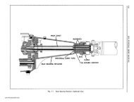
7. Install primary shaft thrust washer and inner<br />
throttle shaft arm (Fig. 6B-<strong>57</strong>).<br />
8. Install outer throttle lever (Fig. 6B-58).<br />
9. Install throttle shaft dog, washer, and screw.<br />
Hook throttle flex spring on outer throttle lever and<br />
throttle shaft dog (Fig. 6B-59).<br />
10. Using a flat washer on each side of the levers,<br />
install connector rod (Fig. 6B-59). Retain with pin<br />
springs.<br />
11. Install fast idle cam assembly, consisting of<br />
secondary lockout lever spring, secondary lockout<br />
lever, lower choke lever, fast idle cam and spring and<br />
attaching screw as follows:<br />
a. Assemble fast idle cam and spring assembly and<br />
lower choke lever and place over attaching screw and<br />
set aside (Fig. 6B-60).<br />
b. Hook secondary lockout lever spring in lockout<br />
lever and place lever against boss with spring hooked<br />
on casting (Fig. 6B-61).<br />
c. Install fast idle cam assembly with screw (assembled<br />
in step a) in position on boss (Fig. 6B-62).<br />
Make sure cam and levers operate freely.<br />
12. Install idle speed screw and spring.<br />
Fig. 68-<strong>57</strong><br />
Inner Throttle Shaft Arm Installed<br />
Fig. 6B-59<br />
Proper Assembly of Primary and Secondary<br />
Throttle Levers<br />
www.<strong>Pontiac</strong><strong>Safari</strong>.com