

SloanStone EW-72000/73000 Installation Instructions - Sloan Valve ...
SloanStone EW-72000/73000 Installation Instructions - Sloan Valve ...
SloanStone EW-72000/73000 Installation Instructions - Sloan Valve ...

You also want an ePaper? Increase the reach of your titles
YUMPU automatically turns print PDFs into web optimized ePapers that Google loves.
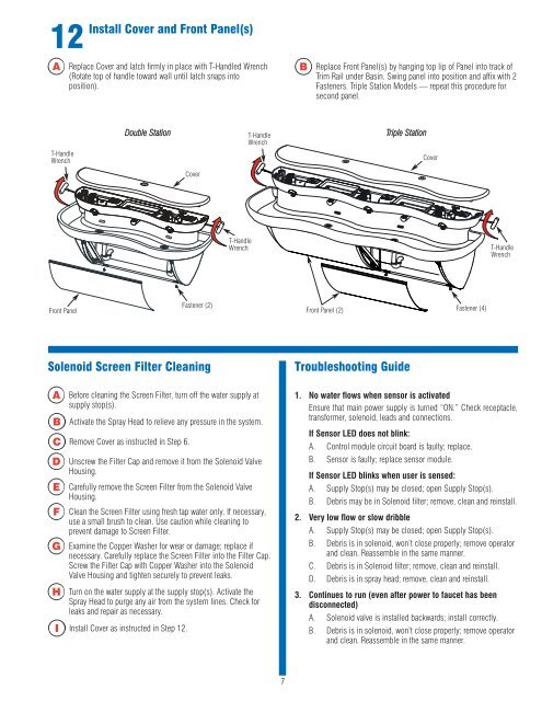
12<br />
Install Cover and Front Panel(s)<br />
A<br />
Replace Cover and latch firmly in place with T-Handled Wrench<br />
(Rotate top of handle toward wall until latch snaps into<br />
position).<br />
B<br />
Replace Front Panel(s) by hanging top lip of Panel into track of<br />
Trim Rail under Basin. Swing panel into position and affix with 2<br />
Fasteners. Triple Station Models — repeat this procedure for<br />
second panel.<br />
Double Station<br />
T-Handle<br />
Wrench<br />
Triple Station<br />
T-Handle<br />
Wrench<br />
Cover<br />
Cover<br />
T-Handle<br />
Wrench<br />
T-Handle<br />
Wrench<br />
Front Panel<br />
Fastener (2)<br />
Front Panel (2)<br />
Fastener (4)<br />
Solenoid Screen Filter Cleaning<br />
Troubleshooting Guide<br />
A<br />
B<br />
D<br />
E<br />
F<br />
G<br />
H<br />
Before cleaning the Screen Filter, turn off the water supply at<br />
supply stop(s).<br />
Activate the Spray Head to relieve any pressure in the system.<br />
C Remove Cover as instructed in Step 6.<br />
Unscrew the Filter Cap and remove it from the Solenoid <strong>Valve</strong><br />
Housing.<br />
Carefully remove the Screen Filter from the Solenoid <strong>Valve</strong><br />
Housing.<br />
Clean the Screen Filter using fresh tap water only. If necessary,<br />
use a small brush to clean. Use caution while cleaning to<br />
prevent damage to Screen Filter.<br />
Examine the Copper Washer for wear or damage; replace if<br />
necessary. Carefully replace the Screen Filter into the Filter Cap.<br />
Screw the Filter Cap with Copper Washer into the Solenoid<br />
<strong>Valve</strong> Housing and tighten securely to prevent leaks.<br />
Turn on the water supply at the supply stop(s). Activate the<br />
Spray Head to purge any air from the system lines. Check for<br />
leaks and repair as necessary.<br />
I Install Cover as instructed in Step 12.<br />
1. No water flows when sensor is activated<br />
Ensure that main power supply is turned “ON.” Check receptacle,<br />
transformer, solenoid, leads and connections.<br />
If Sensor LED does not blink:<br />
A. Control module circuit board is faulty; replace.<br />
B. Sensor is faulty; replace sensor module.<br />
If Sensor LED blinks when user is sensed:<br />
A. Supply Stop(s) may be closed; open Supply Stop(s).<br />
B. Debris may be in Solenoid filter; remove, clean and reinstall.<br />
2. Very low flow or slow dribble<br />
A. Supply Stop(s) may be closed; open Supply Stop(s).<br />
B. Debris is in solenoid, won’t close properly; remove operator<br />
and clean. Reassemble in the same manner.<br />
C. Debris is in Solenoid filter; remove, clean and reinstall.<br />
D. Debris is in spray head; remove, clean and reinstall.<br />
3. Continues to run (even after power to faucet has been<br />
disconnected)<br />
A. Solenoid valve is installed backwards; install correctly.<br />
B. Debris is in solenoid, won’t close properly; remove operator<br />
and clean. Reassemble in the same manner.<br />
7


