SloanStone EW-72000/73000 Installation Instructions - Sloan Valve ...
SloanStone EW-72000/73000 Installation Instructions - Sloan Valve ...
SloanStone EW-72000/73000 Installation Instructions - Sloan Valve ...

You also want an ePaper? Increase the reach of your titles
YUMPU automatically turns print PDFs into web optimized ePapers that Google loves.
PRIOR TO INSTALLATION<br />
Prior to installing the <strong>Sloan</strong> Optima <strong>EW</strong>-70000 Series Lavatory System,<br />
install the items listed below. Also, refer to the appropriate rough-in<br />
diagram on Page 2.<br />
• Install electrical receptacle(s) for plug-in transformer(s) — 120 VAC,<br />
2 amp service for each ETF-233 (24 VAC, 35 VA) plug-in transformer<br />
used.<br />
• Hot and cold water supply lines or tempered water supply line (If there<br />
is no tempered water supply, install thermostatic mixing valve<br />
between hot and cold water supply)<br />
• Drain lines<br />
Important:<br />
• ADEQUATE STRUCTURAL SUPPORT IN OR BEHIND THE WALL IS<br />
REQUIRED. REFER TO THE APPROPRIATE ROUGH-IN DIAGRAM ON<br />
PAGE 2 FOR DRY WEIGHT OF SINK. STRUCTURAL SUPPORT<br />
MUST HAVE A MINIMUM PULLOUT RATING OF 1000 POUNDS<br />
(450 Kg) FOR EACH FASTENER.<br />
• ALL ELECTRICAL WIRING SHOULD BE INSTALLED IN ACCORDANCE<br />
WITH NATIONAL/LOCAL CODES AND REGULATIONS.<br />
• ALL PLUMBING SHOULD BE INSTALLED IN ACCORDANCE WITH<br />
APPLICABLE CODES AND REGULATIONS.<br />
• A 24 VAC STEP-DOWN TRANSFORMER MUST BE USED FOR<br />
HARDWIRE APPLICATIONS.<br />
• USE APPROPRIATE PRECAUTIONS WHILE CONNECTING<br />
TRANSFORMER TO 120 VAC POWER SOURCE.<br />
• DO NOT PLUG TRANSFORMER INTO POWER SOURCE (RECEPTACLE)<br />
UNTIL ALL WIRING IS COMPLETED. PERMANENT DAMAGE TO THE<br />
TRANSFORMER AND CIRCUIT CONTROL MODULE WILL RESULT IF<br />
24 VAC WIRES TOUCH EACH OTHER OR SHORT WHEN POWER<br />
SUPPLY IS ACTIVE.<br />
• BEFORE CONNECTING FLEX HOSES TO SUPPLY STOPS, FLUSH ALL<br />
WATER LINES UNTIL WATER IS CLEAR.<br />
TOOLS REQUIRED FOR INSTALLATION<br />
• Electric drill for drilling anchor holes.<br />
• Standard sockets and open end wrench set for installing anchoring<br />
fasteners and connecting water lines.<br />
• Pipe wrench for installing drain lines.<br />
• Phillips and straight blade screwdrivers.<br />
SINK LOCATION<br />
Determine the appropriate wall location for the Lavatory System.<br />
Consider that hot and cold water supply lines, drain lines, and an<br />
electrical source (receptacle or wiring depending on type of transformer<br />
used) will be required. Compare the physical dimensions of the Lavatory<br />
System to the space available for the installation. If wall is not load<br />
bearing, a carrier may be required behind the wall. Refer to the<br />
appropriate Rough-in diagram on Page 2 for Lavatory System<br />
dimensions.<br />
Prior to Lavatory System installation, electric wiring, water supply and<br />
drain must be installed.<br />
1<br />
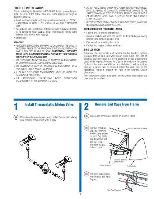
Install<br />
Thermostatic Mixing <strong>Valve</strong><br />
2<br />
Remove<br />
End Caps from Frame<br />
A<br />
If there is no tempered water supply, install Thermostatic Mixing<br />
<strong>Valve</strong> between hot and cold water supply.<br />
A<br />
Loosen (do not remove) screws on inside of frame.<br />
B<br />
Remove both End<br />
Caps by removing<br />
the two outer screws<br />
on each Cap. Slide<br />
Cap forward in slot<br />
and pull it out<br />
through enlarged<br />
hole in Frame.<br />
Bottom Backside of Frame<br />
Enlarged Hole and<br />
Slot in Frame<br />
Front of Frame<br />
End Cap (2)<br />
C<br />
For triple station sinks,<br />
remove the Front Panel<br />
Support.<br />
3<br />
Front Panel Support